A Study on Modeling of VSI based Single-Phase to Three-Phase
Drive System
Konam Ramesh1, Sridhar Konam2,
1M.Tech (power system), Department of Electrical and Electronics Engineering. Email:[email protected] 2M.Tech (power system), Department of Electrical and Electronics Engineering. Email: [email protected]
Abstract : The power electronics device which converts DC power to AC power at required output voltage and frequency level is known as inverter. Multilevel inverter is to synthesize a near sinusoidal voltage from several levels of dc voltages. A single-phase to three-phase drive system composed of two parallel single-phase rectifiers, a three-phase inverter and an induction motor was proposed. The system combines two parallel rectifier without the use of transformers. The system model and the control strategy, including the PWM technique, have been developed. The main objective of this paper is to reduce the circulating currents. Finally with developed fuzzy logic controller strategy, pulse width modulation (PWM) the total harmonic distortion and elimination of error in the voltage are decreased. We also simulated results with Matlab Simulink and three phase drive system performance.
Keywords: AC-DC-AC power converter, drive
system, fault identification, Control strategy
I. INTRODUCTION
DC motors have been used during the last century in industries for variable speed applications, because its flux and torque can be controlled easily by means of changing the field and armature currents respectively. Furthermore, operation in the four quadrants of the torque speed plane including temporary standstill was achieved. Almost for a century, induction motor has been the workhorse of industry due to its robustness, low cost high efficiency and less maintenance. The induction motors were mainly used for essentially constant speed applications because of the unavailability of the variable- frequency voltage supply. The advancement of power electronics has made it possible to vary the frequency of the voltage supplies relatively easy, thus extending the use of the induction motor in variable speed drive applications. But due to the inherent coupling of flux and torque components in induction motor, it
could not provide the torque performance as good as the DC motor. In AC grid connected motor drives, a rectifier, usually a common diode bridge providing a pulsed DC voltage from the mains is required. Although the basic circuit for an inverter may seem simple, accurately switching these devices provides a number of challenges. The most common switching technique is called Pulse Width Modulation (PWM). PWM is a powerful technique for controlling analog circuits with a processor’s digital outputs. PWM is employed in a wide variety of applications like UPS, electric drives, HVDC reactive power compensators in power systems, ranging from measurement and communications to power control and conversion. In AC motor drives, PWM inverters make it possible to control both frequency and magnitude of the voltage and current applied to a motor. As a result, PWM inverter-powered motor drives are more variable and offer in a wide range better efficiency and higher performance when compared to fixed frequency motor drives. The energy, which is delivered by the PWM inverter to the AC motor, is controlled by PWM signals applied to the gates of the power switches at different times for varying durations to produce the desired output waveform. To improve the quality of the product, variable speed is required, for that step less speed control is required. Depending on the type of load and the type of speed different methods are adopted for speed control of motors.
II. SYSTEM MODEL
conventional VSI can be applied. On the other hand, the switch on the DC link must actively operate.
The recent advancement in power electronics has initiated to improve the level of the inverter instead of increasing the size of the filter. In multilevel inverter, design involves parallel connection of the inverter. For these redundant switching a space vector modulation is needed which is based on vector selection in dq stationary reference frame. For a multi-level system either space vector modulation or sinusoidal triangle modulation may be taken. However space vector modulation is having more advantages due to low harmonic production.
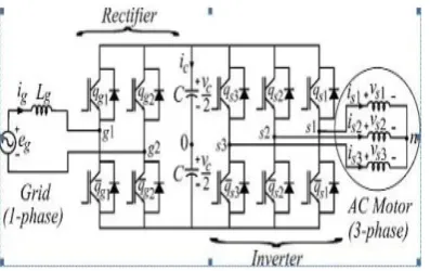
Fig 1 Conventional single-phase to three-phase system
The performance of the multi-level inverter is better than the classical inverter. The total harmonic distortion of the classical inverter is very high. The diode clamped inverter provides multiple voltage levels from a series capacitor bank. The voltage across the switches is only half of the DC bus voltage. These features effectively double the power rating of
Fig 2 Modified (proposed) single-phase to 3-phase drive topology
The inverter contains of many switches and .
--- (1)
--- (2)
--- (3)
--- (4)
--- (5)
Where p = d/dt and symbols like r and l represent the resistances and inductances of the input inductors . The circulating current can be defined from . --- (6)
Introducing and adding (3) and (4), relations (1)– (4) become --- (7)
--- (8)
--- (9)
Where --- (10)
--- (11)
rectifier dynamic model. Therefore, (rectifier A), (rectifier B), and (rectifiers A and B) are used to regulate currents respectively. Reference
currents and are chosen equal to and the
reference circulating current is chosen equal to 0.
In order to both facilitate the control and share equally current, voltage, and power between the rectifiers, the four inductors should be equal,
i.e. and
. In this case, the model (7)–(9) can be simplified to the model given by
+ = ---13)
= --- (14)
= --- (15)
Additionally, the equations for , and can be written as
= = --- (16)
= ---- (17)
+ = …….. (18)
=0. …….. (19)
When =0 ( ) the system model
In this ideal case (four identical inductors), the circulating current can be reduced to zero imposing.
(7)– (9) is reduced to
2( + ) ……… (20)
2( + ) …. (21)
III. PWM STRATEGY
The PWM strategy for the rectifier will be presented. Here we use voltage source inverter strategy [6]. The rectifier pole voltages and depend on the conduction states of the power switches, i.e.
= (2 -1) , for j=a1 to b2
………….. (22)
Where is the total dc-link voltage. Considering that , and denote the reference voltages determined by the current controllers.
………. (23)
……… (24)
………. (25)
Here gating signals are directly calculated from the
reference pole voltages and .
However, (23)–(25) are inadequate to determine the 4 pole voltages uniquely from , and . Introducing an auxiliary variable = , that equation plus the three equations (23)–(25) constitute a four independent equations system
with 4 variables ( and ). Now
solving this system of equations, we get
= ……… (26)
= ……….. (27)
…… (28)
………… (29)
From these equations, it can be seen that, besides , and , the pole voltages depend on also of . The limit values of the variable can be calculated by taking into account the maximum and minimum – value of the pole voltages.
……… (30)
……… (31)
Where is the reference dc-link voltages, =
max ϑ and = minϑ, with ϑ=
{
}.Introducing a parameter μ (0 ≤ μ ≤ 1), the variable can be written as
……. (32)
When μ = 0, μ = 0.5, and μ = 1 the auxiliary variable has the following values = , =
= ( + )/2and = ,
respectively. When = or then
the leg of converter works with certainly zero switching frequency.
IV. CONTROLSTRATEGY
Fig. 3. Control block diagram.
Here we employ a voltage-oriented control (VOC) for obtaining 3-phase system [7] to control PF and harmonics at grid side.
V. HARMONIC DISTORTION
As we know that harmonic distortion of the proposed converter and its voltages had been analyzed with the help of weighted THD (WTHD). It is solved by using
....
(33)
Where is treated as amplitude of fundamental voltage and is treated as amplitude of ith harmonic and also p may be number of harmonics in this consideration
.
VI. FAULT COMPENSATION
At the rectifier or inverter converter stages fault compensation can be achieved by considering power converter topology and get reconfigure it by isolating devices fast active fuses— , j = 1 . . . , 7) and connecting devices (back to back connected SCRs—t1, t2, t3), as depicted in Fig.4.As shown in fig.5 block diagram of fault diagnosis system consists of block fault identification system (FIS) that detects and exactly locates the faulty switches in the unit, determines the leg to be isolated from the system.
Fig.4. fault-tolerant system.
Fig. 5 fault diagnosis system.
VII.EXPERIMENTAL RESULTS
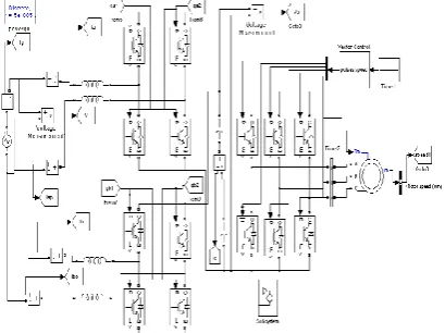
To study the operation of the Three-Phase Drive System, it is implemented in MATLAB/SIMULINK environment. The model is shown in Fig.6
Fig. 7 (a): Supply Voltage and Current
Fig. 7 (b): Capacitor Voltage
Transient means immediately after any fault (or) disturbances or abnormal conditions like 0^+, 0^- after some time it will reaches to steady state condition. Time taken of study state is 0.25 m sec in this condition we take graph between the supply voltage (volts), supply current (Amps) as a function of Time (msec).In this condition we can also check the capacitor voltage. At capacitor value is 100V.
X-axis = Time (msec), Y-axis = Capacitor voltage (volts).This graph is shown in the figure 7(b)
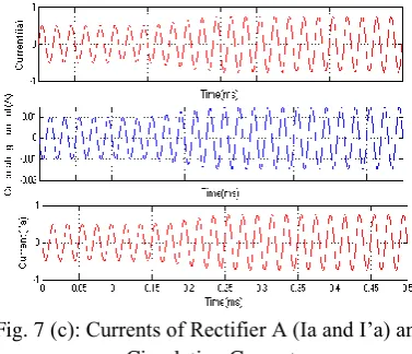
Fig. 7 (c): Currents of Rectifier A (Ia and I’a) and Circulating Current
In this condition we can take rectifier A currents (Ia), (I’a) and this difference is circulating current. Rectifier A currents Ia is 4A I’a is 4A then the circulating current is ZERO.
Circulating current (io) = (Ia) - (I’a)
=4-4 =0A
X-axis = Time (msec), Y-axis = Circulating current (io) current (ia) & currents (I’a). This graph is shown in the figure 7(c)
Fig.7 (d): Currents of rectifier B (Ib and I’b) and Circulating Current
In this condition we can take rectifier A currents (Ib), (I’b) and this difference is circulating current. R rectifier B currents Ib is 1A I’b is 4A then the circulating current is ZERO Circulating current (io) = (Ib) - (I’b) = 4-4 = 0A
Simulation Results for Fault at Rectifier B
Fig. 8(a): Supply Voltage and Supply Current
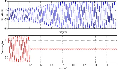
Fig .8(b): DC Link Capacitor Voltage
Here supply voltage is 110V and supply current is 8 Amp. In that time we can take the graph between supply voltage (Volts), supply current (Amps) as a function time (msec). In the same way fault is in the rectifier B we can also check the on DC link voltage side. Here capacitor voltage is 110V, when fault occurred rectifier b capacitor voltage decreases and again it reaches to 100V. In this condition we can take rectifier A currents (ia), (i’a) and this difference is circulating current.
Fig 8(c): Currents of Rectifier A and Circulating Current
Rectifier A currents Ia is 4A I’a is 4A then the circulating current is ZERO. Circulating current (io) = (Ia) - (I’a) =4-4 =0A
X-axis = Time (msec), Y-axis = Circulating current (io) current (ia) & currents (I’a). This graph is shown in the fig. 8(c)
Fig 8(d): Currents of Rectifier A and B
And also check the rectifier A and rectifier B currents then here we can see the one difference of the both rectifiers, in rectifier A is continuously supply the voltage and rectifier B is not giving continuous supply because fault is occurred at rectifier B.X-axis = Time (msec), Y-axis = current of rectifier A, current of rectifier B (Amps).This graph is shown in the fig 8(d). We extended our work to have better results by adopting Fuzzy Logic Toolbox software with MATLAB technical computing software as a tool for solving problems with fuzzy logic that involves more benefits as shown in fig.9
Fig.9 fuzzy based topology for optimized results
As shown in Fig.9 we observe that compared to PI controller THD has been decreased to at 3.05% as compared with pi controller.In PI controller THD was reduced to a percentail 85.2%.
VIII. CONCLUSION
In our proposed scheme topology consists of combination of two rectifiers without employing transformers. From the above observations are concluded finally as follows:
i. Further reduces the switching currents, ii. Total harmonic distortion present in the
grid, and
iii. To further increases fault tolerance currents.
iv. Moreover as compared to conventional systems losses in proposed are greatly reduced to have an efficient topology.
The experimental results have proved to be system is greatly controlled, even with transient and occurrence of faults.
REFERENCES
Ind. Appl., vol. 29, no. 2, pp. 806–813, Jul./Aug. 1993.
[2] J. Itoh and K. Fujita, ―Novel unity power factor circuits using zero-vector control for single-phase input systems,‖ IEEE Trans. Power Electron., vol. 15, no. 1, pp. 36–43, Jan. 2000.
[3] B. K. Lee, B. Fahimi, and M. Ehsani, ―Overview of reduced parts converter topologies for AC motor drives,‖ in Proc. IEEE PESC, 2001, pp. 2019–2024.
[4] C.B.Jacobina, M.B.deR.Correa, A.M.N. ima, and E.R.C.daSilva,―AC motor drive systems with a reduced switch count converter,‖ IEEE Trans. Ind. Appl., vol. 39, no. 5, pp. 1333–1342, Sep./Oct. 2003.
[5] R. Q. Machado, S. Buso, and J. A. Pomilio, ―A line-interactive single phase to three-phase converter system,‖ IEEE Trans. Power Electron. Vol. 21, no. 6, pp. 1628–1636, May 2006.
[6] C. B. Jacobina, E. C. dos Santos Jr., E. R. C. da Silva, M. B. R. Correa,A. M. N. Lima, and T. M. Oliveira, ―Reduced switch count multiple three phase ac machine drive systems,‖ IEEE Trans. Power Electron., vol. 23,no. 2, pp. 966–976, Mar. 2008.
[7] M. Malinowski, M. P. Kazmierkowski, and A. M. Trzynadlowski, ―A comparative study of control techniques for PWM rectifiers in AC adjustable speed drives,‖IEEE Trans. Power Electron., vol. 18, no. 6, pp. 1390–1396, Nov. 2003.
[8] A. M. Trzynadlowski, R. L. Kirlin, and S. F. Legowski, ―Space vector PWM technique with minimum switching losses and a variable pulse rate,‖ IEEE Trans. Ind. Electron., vol. 44, no. 2, pp. 173–181, Apr. 1997.
[9] B.L.Theraja, A.K.Theraja ―Electrical Technology Volume II, AC & DC Machines‖.
[10] P.S.Bimhra, ―A textbook of power electronics‖.
[11] S. K. Mazumder, ―Continuous and discrete variable-structure controls for parallel three-phase boost rectifier, IEEE Trans. Ind. Electron., vol. 52, no. 2, pp. 340–354, Apr. 2005.
[12] Z. Ye, P. Jain, and P. Sen, ―Circulating current minimization in high frequency AC power distribution architecture with multiple inverter modules operated in parallel, IEEE Trans. Ind. Electron., vol. 54, no. 5,. pp. 2673–2687, Oct. 2007.
[13] J. Holtz, ―Pulse width modulation for electronic power conversion, Proc.IEEE, vol. 82, no. 8, pp. 1194–1214, Aug. 1994.
[14] M. P. Kazmierkowski and L. Malesani, ―Current control techniques for three-phase voltage-source PWM converters: A survey, IEEE Trans. Ind.Electron., vol. 45, no. 5, pp. 691–703, Oct. 1998.
[15] B. A. Welchko, T. A. Lipo, T. M. Jahns, and S. E. Schulz, ―Fault tolerant three-phase AC motor drive topologies: A comparison of features, cost, and limitations, IEEE Trans. Power Electron., vol. 19, no. 4, pp. 1108–1116, Jul. 2004.
BIODATA:
Konam Ramesh completed M.tech (power system).