Available online:
https://edupediapublications.org/journals/index.php/IJR/
P a g e | 167Design and Analysis of Two Wheeler Shock Absorber Coil Spring
G murthi Prasad Rao
Assistant Professor, Department of Mechanical Engineering, visvesvaraya college of engineering and
technology
.
[email protected]
Abstract:
In vehicles problem happens while driving on bumping road condition. The objective of this project is to design and analyze the performance of Shock absorber by varying the wire diameter of the coil spring. The Shock absorber which is one of the Suspension systems is designed mechanically to handle shock impulse and dissipate kinetic energy. It reduces the amplitude of disturbances leading to increase in comfort and improved ride quality. The spring is compressed quickly when the wheel strikes the bump. The compressed spring rebound to its normal dimension or normal loaded length which causes the body to be lifted. The spring goes down below its normal height when the weight of the vehicle pushes the spring down. This, in turn, causes the spring to rebound again. The spring bouncing process occurs over and over every less each time, until the up-and-down movement finally stops. The vehicle handling becomes very difficult and leads to uncomfortable ride when bouncing is allowed uncontrolled. Hence, the designing of spring in a suspension system is very crucial. The analysis is done by considering bike mass, loads, and no of persons seated on bike. Comparison is done by varying the wire diameter of the coil spring to verify the best dimension for the spring in shock absorber. Modeling and Analysis is done using Pro/ENGINEER and ANSYS respectively.Key Words:
Shock Absorber, Coil Spring, Modified design, Stress analysis.I. Introduction
The Shock absorber which is one of the Suspension systems is designed mechanically to handle shock impulse and dissipate kinetic energy. It reduces the amplitude of disturbances leading to increase in comfort and improved ride quality. Hence, the designing of spring in a suspension system is very crucial.
Design in an important industrial activity which influences the quality of the product. The Shock absorber coil spring is designed by using the modeling software Pro/ENGINEER Wildfire 4.0. In modeling the time is spent in drawing the coil spring model and the risk involved in design and manufacturing process can be easily minimized. So the modeling of the coil spring is made by using Pro/ENGINEER. Later this Pro/ENGINEER model is imported to ANSYS for the analysis work. The ANSYS software is used for analyzing the component by varying the load applied on it and the results are observed. A solver mode in ANSYS software calculates the stresses and their relation without manual interventions thereby reducing the time compared with the manual theoretical work.
A. Applications
Shock absorbers are an important part of automobile and motorcycle suspensions, aircraft landing gear, and the supports for many industrial machines. Large shock absorbers have also been used in structural engineering to reduce the susceptibility of structures to earthquake damage and resonance. A transverse mounted shock absorber, called a yaw damper, helps keep railcars from swaying excessively from side to side and are important in passenger railroads, commuter rail and rapid transit systems because they prevent railcars from damaging station platforms.
B. Structures
Applied to a structure such as a building or bridge it may be part of a seismic retrofit or as part of new, earthquake resistant construction. In this application it allows yet restrains motion and absorbs resonant energy, which can cause excessive motion and eventual structural failure.
C. Shock Absorber types
There are a number of different methods of converting an impact /collision into relatively smooth cushioned contact. Metal Spring
Rubber Buffer Hydraulic Dashpot Collapsing safety Shock Absorbers Pneumatic Cylinders
Self compensating Hydraulic
D. Working of shock absorbers Spring:
Shock absorbers work in two cycles--the compression cycle and the extension cycle. The compression cycle occurs as the piston moves downward, compressing the hydraulic fluid in the chamber below the piston. The extension cycle occurs as the piston moves toward the top of the pressure tube, compressing the fluid in the chamber above the piston. A typical car or light truck will have more resistance during its extension cycle than its compression cycle. With that in mind, the compression cycle controls the motion of the vehicle's unsprung weight, while extension controls the heavier, sprung weight.
II.
ObjectiveMarch 2018
Available online:
https://edupediapublications.org/journals/index.php/IJR/
P a g e | 168spring goes down below its normal height when the weight of the vehicle pushes the spring down. This, in turn, causes the spring to rebound again. The spring bouncing process occurs over and over every less each time, until the up-and-down
movement finally stops. The vehicle handling becomes very difficult and leads to uncomfortable ride when bouncing is allowed uncontrolled. The designing of spring in a suspension system is very crucial.
III.
Design Calculation For Helical Coil Spring Of The Shock Absorber
Material: Spring Steel (modulus of rigidity) G =78600N/mm2 Mean diameter of a coil, D=33.3mm Diameter of wire, d = 6.7mm
Total no of coils, n1= 17 Height, h = 210mm
Outer diameter of spring coil, D0 = D +d =40mm No of active turns, n= 15
Weight of bike = 131kg Let weight of 1person = 75Kg Weight of 2 persons = 75×2=150Kg Weight of bike + persons = 263Kg Rear Suspension = 65%
65% of 263 = 171Kg
Considering dynamic loads it will be double W = 342Kg = 3355N
For single shock absorber weight = w/2= 1677N = W We Know that, compression of spring (δ ) = WD3n
G.d4 C = spring index = D = 5
d ( δ ) = 46.91
Solid length, Ls =n1×d=17×6.7=113.9mm
Free length of spring,
Lf = solid length + maximum compression + clearance between adjustable coils = 113.9 + 46.91 + (46.91 ×0.15 ) = 167.8mm
Spring rate, K = W = 35.74
δ
Pitch of coil, P = Lf – Ls + d n1
Stresses in helical spring: maximum shear stress induced in the wire
τ = Ks × 8WD .d3
Ks = 4C-1 + 0.615 = 1.3105
4C-4 C
τ = 619.62
Buckling of compression spring:
Crippling load under which a spring may buckle KL = 0.1 (for hinged end spring)
The buckling factor for the hinged end and built -in end spring Wcr = q × KL × Lf = 35.74 × 0.1× 167.8 = 599.71N
IV.
Introducti on To
Pro/Engineer
Pro/ENGINEER is a feature based, parametric solid modeling program. As such, it's use is significantly different from conventional drafting programs. In conventional drafting (either manual or computer assisted), various views of a part are created in an attempt to describe the geometry.. Another unique attribute of Pro/ENGINEER is that it is a solid modeling program. The design procedure is to create a model, view it, assemble parts as required, then
Available online:
https://edupediapublications.org/journals/index.php/IJR/
P a g e | 169drawing with critical and envelope dimensions shown.
A. Summary of capabilities Like any software it is continually being developed to include new functionality. The details below aim to outline the scope of capabilities to give an overview rather than giving specific details on the individual functionality of the product. Pro/Engineer is a software application within the CAID/CAD/CAM/CAE category, along with other similar products currently on the market. Pro/Engineer is a parametric, feature-based modeling architecture incorporated into a single database philosophy with advanced rule-based design capabilities. The capabilities of the product
can be split into the three main heading of Engineering Design, Analysis and Manufacturing.
B. Engineering Design Pro/Engineer offers a range of tools to enable the generation of a complete digital representation of the product being designed. In addition to the general geometry tools there is also the ability to generate geometry of other integrated design disciplines such as industrial and standard pipe work and complete wiring definitions. Tools are also available to support collaborative development. A number of concept design tools that provide up-front Industrial Design concepts can then be used in the downstream process of engineering the product. These range from conceptual Industrial design sketches, reverse engineering with point cloud data and comprehensive freeform surface tools.
C.Model of the Shock Absorber Coil Spring 1) Present Design of the Coil Spring Spring Dimension
March 2018
Available online:
https://edupediapublications.org/journals/index.php/IJR/
P a g e | 170Fig 5.2 Part drawing of Spring with dimension 6.7
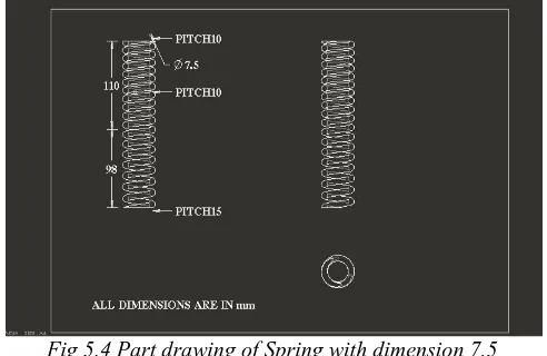
2) Modified Design of the Coil Spring Spring Dimension
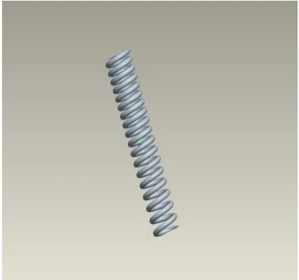
Fig 5.3 Isometric view of Spring with dimension 7.5
Fig 5.4 Part drawing of Spring with dimension 7.5
V.
Analysis Of The
Shock Absorber
Coil Spring
Static analysis calculates the effects of steady loading conditions on a structure, while ignoring inertia and damping effects, such as those caused by time-varying loads. A static analysis, however, includes steady inertia loads (such as gravity and rotational velocity), and time-varyingloads that can be approximated as static equivalent loads
A. ANALYSIS
Available online:
https://edupediapublications.org/journals/index.php/IJR/
P a g e | 171most likely fail due to material failure (that is, the yield stress is exceeded).For the given below specification of the allow wheel, the static analysis is performed using solid works to find the maximum safe stress and the corresponding pay load. After geometric modeling of the alloy wheel with given specifications it is subjected to analysis. The Analysis involves the following discretization called meshing, boundary conditions and loading.
B. About analysis with ANSYS
The reliability of ANSYS software proved by doing valediction problem in simply supported beam, which is shown appendix 1. The theoretical values of simply supported beam compared with ANSYS values and its almost same. So we consider ANSYS software for our analysis to get accurate results. The ANSYS computer program is
a large-scale multipurpose finite element program. ANSYS is used for solving several engineering analyses. The analysis capabilities of ANSYS include the ability to solve static and dynamic structural analyses, steady-state and transient heat transfer problems, mode frequency and buckling eigen value problems, static or time varying magnetic analyses and various types of field and couple field application
C. PRESENT DESIGN
Structural Analysis for bike weight (113kg) Material: Spring Steel (ASTM A227) Modulus of Rigidity G = 78600N/mm2 Properties:Young’s Modulus (EX):1.965×10⁵ N/mm2
Poisson’s Ratio (PRXY): 0.25 Density:7.86×10⁻⁶kg/mm3
LOAD: 113kg
ON APPLYING LOAD:
Fig.6.1 Load applied on tetra mesh model
VI.
Result After Applying LoadMarch 2018
Available online:
https://edupediapublications.org/journals/index.php/IJR/
P a g e | 172Fig.6.3 Von misses stress
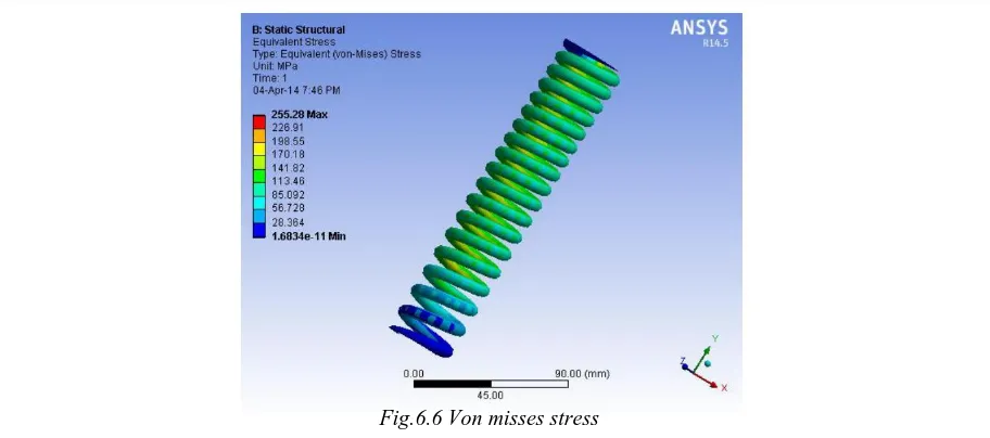
D. NEW MODIFIED DESIGN OF THE SPRING Structural Analysis for bike weight (113kgs) Material: Spring Steel (ASTM A227) Modulus of Rigidity G = 78600N/mm2
Properties:Young’s Modulus (EX):1.965×10⁵ N/mm2 Poisson’s Ratio (PRXY): 0.25
Density: 7.86×10⁻⁶kg/mm3 LOAD: 113kg
ON APPLYING LOAD:
Fig.6.4 Load applied on tetra mesh model
Result After Applying Load:
Available online:
https://edupediapublications.org/journals/index.php/IJR/
P a g e | 173
Fig.6.6 Von misses stress
VII.
Result and Discussion
Stress analysis values for the present and modified design of the shock absorber coil spring
Table 7.1 Stres analysis comparision
STRESSES ON THE SHOCK DEFORMATION OF THE
LOADING ABSORBER COIL SPRING SHOCK ABSORBER
(Mpa) COIL SPRING
S.NO (mm)
NEW NEW
DESCRIPTION LOAD PRESENT MODIFIED PRESENT MODIFIED
DESIGN DESIGN DESIGN DESIGN
BIKE LOAD
113kg 307.56 255.28 10.936 6.9028
1.
2.
BIKE LOAD + 188kg 512.6 425.46 18.227 11.505
1 PERSON
3
BIKE LOAD + 263kg 716.78 594.94 25.488 16.087
2 PERSONS
VIII.
Conclu
sion
We have designed a Shock Absorber used in 160 cc bike and we have modeled it using 3D parametric software called Pro/Engineer. The shock absorber design is modified by reducing the diameter and stress analysis is performed. The stress value is lesser in our designed spring than in original which adds an advantage to our design. By comparing the results in the table we could analyse that our modified spring has reduced in weight and it is safe.REFERENCES
[1] Pinjarla.Poormohan and Lakshmana Kishore T, “Design and Analysis of a Shock Absorber”, International Journal of
Research in Engineering and Technology, ISSN: 2319-1163, Volume: 1, Issue: 4, pp.578-592, December 2012
[2] Kommalapati. Rameshbabu, Tippa Bhimasankar Rao, “Design Evaluation of a two wheeler suspension system for variable load conditions” International Journal of Computational Engineering Research, Vol 03, Issue 4, pp. 279-283 , 2013
[3] Gajendra Singh Rathore and Upendra Kumar Joshi, “Fatigue Stress analysis of helical Compression Spring: A
Review”, International Journal of Emerging Trends in Engineering and Development, ISSN: 2249-6149, Volume: 2,
March 2018
Available online:
https://edupediapublications.org/journals/index.php/IJR/
P a g e | 174[4] B. Pyttel, I. Brunner, B. Kaiser, C. Berger, M. Mahendran, “Fatigue behaviour of helical compression springs at a very high number of cycles–Investigation of various influences”, International Journal of Fatigue (2013), S0142-1123(13)00017-0, JIJF 3037.
[5] Brita Pyttel, K K Ray, Isabell Brunner, Abhishek Tiwari, S. A. Kaoua. “Investigation of probable failure position in helical compression springs used in fuel injection system of diesel engines”, IOSR Journal of Mechanical and Civil Engineering (IOSRJMCE) ISSN: 2278-1684 Volume 2, Issue 3 (Sep-Oct. 2012), PP 24-29. [6] Mehdi Bakhshesh and Majid Bakhshesh.,
“Optimization of Steel Helical Spring by Composite Spring”, International journal of multidisciplinary science and engineering, vol.3, No.6, june 2012.
[7] B. Kaiser , B. Pyttel, C. Berger, “VHCF-behavior of helical compression springs made of different materials”,
International journal of fatigue, vol 33,pp. 23-32,2011.
[8] Yuuji Shimatani, Kazuaki Shiozawa, Takehiro Nakada and Takashi Yoshimoto, “Effect of surface residual stress and inclusion size on fatigue failure mode of matrix HSS in very high cycle regime”, Procedia Engineering 2 (2010) 873–
882.
[9] Y. Prawoto, M. Ikeda , S.K. Manville, A. Nishikawa, “Design and failure modes of automotive suspension springs”,
Engineering Failure Analysis 15 (2008) 1155– 1174.
[10] L.Del Llano-Vizcaya, C. Rubio-Gonzalez, G. Mesmacque. “Stress relief effect on fatigue and relaxation of compression springs”. Material and design 28(2007) 1130-1134.
[11] Chang-Hsuan Chiu, Chung-Li Hwan, Han-Shuin Tsai, Wei-Ping Lee. “An experimental investigation into the mechanical behaviors of helical composite springs”. Composite Structures 77 (2007) 331–340.
[12] C.Berger, B.Kaiser. “Results of very high cycle fatigue tests on helical compression springs”.
International journal of fatiuge 28(2006) 1658-1663.
[13] L. Del Llano-Vizcaya, C.Rubio-Gonzalez, G.Mesmacque ,T. Cervantes-Hernandez. “Multiaxial fatigue and failure analysis of helical compression springs”.Engineering failure analysis 13 (2006) 1303-1313.
[14] Dammak Fakhreddine, Taktak Mohamed, Abid Said, Dhieb Abderrazek,Haddar Mohamed. “Finite element method for the stress analysis of isotropic cylindrica helical spring”. Journal of mechanics A/solids 24 (2005) 1068-1078. [15] B. Ravi Kumar, Swapan K. Das, D.K.
Bhattacharya. “Fatigue failure of helical compression spring in coke oven batteries”. Engineering Failure Analysis 10 (2003) 291–296. [16] Kotaro Watanabe,Masashi Tamura, Ken Yamaya, Takahiko Kunoh. “Development of a new-type suspension spring for rally cars”. Journal of materials processing technology 111 (2001) 132-134.
[17] M.T. Todinov. “Maximum principal tensile stress and fatigue crack origin for compression springs”. International
Journal of Mechanical Sciences 41 (1999) 357-370
[18] James M. Meagher and Peter Altman. “Stresses from flexure in composite helical implantable leads” S1350-4533(96) 00022-7.
Books:
[19] Bhandari V B.Design of machine elements. New York: Tata McGraw-Hill; 1994.
[20] Shigley J. Mechanical engineering design. New York: McGraw-Hill; 1981.
[21] Carlson H. Spring designer’s handbook. New York: Marcel Dekker Inc.; 1978.
[22] John C. Dixon, The Shock Absorber Handbook. John Wiley & Sons, Ltd; 2007.