
A
BSTRACT
MATTOS, LEONARDO SERRA. Towards the Automation of Embryonic Stem Cell Microinjections into Blastocysts. (Under the direction of Edward Grant.)
The purpose of the research has been to increase the consistency and efficiency
rates of blastocyst microinjections through automation. The research involved the design,
implementation, and evaluation of a novel biomanipulation system that is a test-bed for
applying intelligent control algorithms. The microinjection process was controlled from a
computer via a joystick or by software controllers. These included real-time video
processing for the acquisition of experimental data and control. Teleoperated
microinjections under the control of both expert and novice operators showed that the
system is effective, easy to use, and capable of eliminating the need for the extensive
training of microinjection personnel. Experimental results showed that all operators
obtained a microinjection success rate over 80%, demonstrating a significant improvement
over the tradition manual microinjections. Furthermore, blastocysts injected using this
system were more likely to develop to term, and to yield chimeras, than blastocysts
injected using the traditional manual method. The experiments also highlighted common
problems encountered during the blastocyst microinjection stage, allowing the design and
development of effective control algorithms to guide the teleoperated and automatic
microinjections. Overall, this research contributed to the full automation of blastocyst
microinjection by: 1) significantly improving the microinjection process; 2) significantly
that enable real-time template matching; 5) creating new algorithms to identify and analyze
blastocyst images; 6) designing and conducting preliminary tests with control algorithms
TOWARDS THE AUTOMATION OF EMBRYONIC STEM CELL MICROINJECTIONS INTO BLASTOCYSTS
by
LEONARDO SERRA MATTOS
A dissertation submitted to the Graduate Faculty of North Carolina State University
in partial fulfillment of the requirements for the Degree of
Doctor of Philosophy
ELECTRICAL ENGINEERING
Raleigh, North Carolina May 2007
D
EDICATION
To my family,
B
IOGRAPHY
Leonardo Serra Mattos grew up in Brazil and began working with robots and
automation systems while attending the Campinas’ Technical College
(COTUCA-UNICAMP, Campinas, Brazil), from which he earned a Technical degree in Electronics in
1992. Leonardo maintained his involvement in the automation area while attending
college at the University of Sao Paulo (USP, São Carlos, Brazil), where he earned a
Bachelor of Science degree in Electrical Engineering in 1998.
After college Leonardo gained industry exposure and hands-on experience with
robots and automated machines while working for Fanuc America Corporation in the
United States. His interests in research and development of new technologies, however,
took him back to school, and Leonardo started graduate studies in 2001.
Leonardo joined the Center for Robotics and Intelligent Machines (CRIM) in 2002,
where he got involved in several multi-disciplinary research projects. These included
research in biorobotics, medical robotics, e-textiles, evolutionary robotics, instrumentation,
acoustic arrays, rehabilitation engineering, and remote sensing.
Mattos received his Master of Sciences degree in Electrical Engineering from the
North Carolina State University (NCSU, Raleigh, USA) in 2003, after which he continued
his graduate studies pursuing a Doctor of Philosophy degree also in Electrical Engineering.
His efforts towards that degree were concluded with this dissertation.
Leonardo Mattos is a member of IEEE, IEEE Robotics and Automation Society,
A
CKNOWLEDGEMENTS
I would like to express my deep gratitude to my advisor, Dr. Edward Grant, and to
Dr. Randy Thresher for their continuous involvement and support during this research.
Many thanks to Kim Kluckman as well, for her ideas, enthusiasm and all of the help
provided during the setup and experimentation phases of this research.
I would also like to thank Dr. John Muth and Dr. Troy Nagle, from the NCSU’s
ECE Department, and Dr. Marzluff and Dr. Corvinus, from the UNC’s School of
Medicine, for the acquisition of equipment employed in this research.
In addition, I would like to thank all members of the Center for Robotics and
Intelligent Machines for their friendship, help, and support.
T
ABLE OF
C
ONTENTS
LIST OF TABLES ...ix
LIST OF FIGURES ...x
1. INTRODUCTION TO BIOMANIPULATION ...1
1.1. BIOMANIPULATION TECHNIQUES...3
1.1.1. Contact Techniques for Biomanipulation...4
1.1.1.1. Manual Mechanical Micromanipulation... 4
1.1.1.2. Atomic Force Microscopy/Manipulation... 5
1.1.2. Non-Contact Techniques for Biomanipulation...7
1.1.2.1. Electrowetting ... 7
1.1.2.2. Dielectrophoresis... 9
1.1.2.3. Laser Trapping ... 10
1.1.2.4. Electro-Rotation ... 11
1.1.2.5. Thermal Gelation... 11
1.2. MICROINJECTION TECHNOLOGY...12
1.3. BIOMANIPULATION AUTOMATION...12
1.3.1. Computer Vision for Biomanipulations...13
1.3.2. Foremost Efforts Toward Embryo Biomanipulation Automation ...15
1.4. ESCELLS AND THE PROCESS OF GENE TRANSFER INTO THE MOUSE*...18
1.4.1. Details of the Blastocyst Microinjection Process...20
1.5. CONTRIBUTIONS TOWARDS BIOMANIPULATION AUTOMATION...22
2. THE SEMI-AUTOMATED MICROINJECTION SYSTEM...25
2.1. MAIN COMPONENTS...25
2.2. SYSTEM CONFIGURATION...28
2.3. SOFTWARE UNITS...29
2.4. ROBOT CONTROL...32
2.5. XYSTAGE...34
2.6. THE INTERACTIVE USER INTERFACE...35
2.7. CONCLUSIONS...38
3. EXPERIMENTS AND ISSUES RELATED TO SEMI-AUTOMATED BLASTOCYST MICROINJECTION ...40
3.1. EVALUATION OF THE ROBOT CONTROL SYSTEM...41
3.2. SEMI-AUTOMATED MICROINJECTION EXPERIMENTS...43
3.3. ANALYSIS OF FAILED MICROINJECTIONS...50
3.4. RULES FOR BLASTOCYST MICROINJECTIONS...54
3.5. BLASTOCYST ORIENTATION ADJUSTMENTS...56
3.5.1. Blastocyst rotation method based on fluid flow ...57
3.5.2. Push-pull blastocyst rotation method...58
3.5.3. Alternative method for blastocyst rotation ...59
3.6. CONCLUSIONS...59
4. VIDEO PROCESSING ALGORITHMS...62
4.1. OVERVIEW...62
4.2.2. Analyzing the blastocyst orientation ...67
4.2.2.1. Finding the best injection area on the blastocyst ... 68
4.2.2.2. Qualifying the blastocyst orientation... 69
4.3. FINDING AND TRACKING THE PIPETTES...71
4.3.1. Cross-Correlation Template Matching Overview ...72
4.3.2. SSD Template Matching Overview...72
4.3.3. Why Template Matching?...73
4.3.4. Template Acquisition...74
4.4. CONCLUSIONS...75
5. EVALUATION OF THE BLASTOCYST PROCESSING ALGORITHMS ...77
5.1. EXPERIMENTS WITH SYNTHETIC IMAGES...78
5.1.1. Impact of Gaussian Noise ...80
5.1.2. Impact of Impulse Noise...81
5.1.3. Impact of Reducing the Number of Object Pixels...82
5.1.4. Impact of Gaussian Blur ...85
5.2. EXPERIMENTS WITH REAL IMAGES...88
5.2.1. Performance from Undistorted Images...88
5.2.2. Impact of Noise on the Blastocyst Localizations...89
5.2.3. Impact of Noise on the Injection Sector Selection...91
5.2.4. Evaluation of the Blastocyst Orientation Check ...93
5.3. PROCESSING SPEED...94
5.4. CONCLUSIONS...94
6. TEMPLATE MATCHING SPEEDUP ...96
6.1. WINDOW-BASED SEARCH...97
6.2. EXPANDING SEARCH AREA...100
6.3. CONTROLLING THE SEARCH STEP SIZE...102
6.4. USING ONLY NON-ZERO TEMPLATE PIXELS...103
6.5. COMBINING THE SPEED-UP TECHNIQUES...105
6.6. SPEEDING UP THE SSDTEMPLATE MATCHING ALGORITHM...106
6.7. CONCLUSIONS...108
7. EVALUATION OF THE TEMPLATE MATCHING ALGORITHMS...109
7.1. EXPERIMENTS WITH SYNTHETIC IMAGES...110
7.1.1. Video Simulation ...110
7.1.2. Impact of Gaussian Noise ...112
7.1.3. Impact of Impulse Noise...113
7.1.4. Impact of Reduced Number of Object Pixels...115
7.1.5. Impact of Gaussian Blur ...117
7.2. EXPERIMENTS WITH REAL IMAGES...119
7.2.1. Performance from Undistorted Images...120
7.2.2. Impact of Gaussian Noise ...122
7.2.3. Impact of Impulse Noise...127
7.2.4. Impact of Gaussian Blur ...131
7.3. CONCLUSIONS...135
8. BLASTOCYST MICROINJECTION AUTOMATION ...137
8.1. SYSTEM CONFIGURATION FOR AUTOMATIC MICROINJECTIONS...137
8.2. TELEOPERATED TRIALS WITH THE NEW SYSTEM CONFIGURATION...141
8.3. AUTOMATION ALGORITHMS...142
8.3.1. Automatic Blastocyst Delivery ...143
8.3.3. Automatic Blastocyst Release...145
8.3.4. Automatic Blastocyst Orientation ...146
8.3.5. Automatic Blastocyst Collection ...147
8.3.6. Automatic Motion Control ...148
8.3.6.1. Visual Servoing ... 149
8.3.6.2. Automation Algorithm ... 151
8.3.7. ES Cells Delivery ...152
8.3.7.1. Proposed Automation Algorithm... 152
8.3.7.2. Proposed ES Cells Counter Algorithm ... 153
8.3.8. Automatic Microinjections ...155
8.3.9. Process Automation ...156
8.4. CONCLUSIONS...157
9. EXPERIMENTS WITH AUTOMATED MICROMANIPULATION ROUTINES...160
9.1. AUTOMATIC BLASTOCYST DELIVERY TRIALS...160
9.2. AUTOMATIC BLASTOCYST CAPTURE TRIALS...162
9.3. AUTOMATIC BLASTOCYST RELEASE AND COLLECTION TRIALS...163
9.4. AUTOMATIC BLASTOCYST ORIENTATION TRIALS...164
9.5. AUTOMATIC MOTION CONTROL TRIALS...164
9.6. AUTOMATIC MICROINJECTION TRIALS...164
9.7. CONCLUSIONS...169
10. SUGGESTIONS FOR IMPROVEMENTS AND FUTURE RESEARCH ...172
10.1. MICROINJECTION EQUIPMENT UPGRADE...172
10.2. VISION SYSTEM IMPROVEMENTS...173
10.3. FULLY AUTOMATED BLASTOCYST MICROINJECTIONS...175
10.4. INTELLIGENT SYSTEM CONTROL...176
10.5. SYSTEM CONFIGURATION IMPROVEMENTS...177
10.6. RELATED AREAS FOR FUTURE RESEARCH...178
11. CONCLUSIONS ...180
12. REFERENCES...183
APPENDICES ...192
APPENDIX 1. THE BLASTOWORKS SOFTWARE...193
A1.1.SOFTWARE STRUCTURE OVERVIEW...193
A1.2.THE USER INTERFACE MODULE...193
A1.3.IMAGE MANAGEMENT...194
A1.3.1. Image Sources ...194
A1.3.1.1. Live Video... 195
A1.3.1.2. Simulated Video ... 196
A1.3.1.3. Recorded Video... 199
A1.3.1.4. Pictures... 200
A1.3.2. Image Adjustments...200
A1.3.2.1. Image Noise... 201
A1.3.3. Image Processing ...201
A1.3.4. Image Flow...203
A1.4.MOTION MANAGEMENT...203
A1.4.1. Joystick Interface...204
A1.4.2. Robot Interface ...205
A1.4.3. Syringes and Piezo Interface ...206
APPENDIX 2. INTERFACE AND CONTROL BOARD...209
A2.1.INTRODUCTION...209
A2.2.ICBSPECIFICATIONS...210
A2.3.ICBCONNECTORS...211
A2.4.ICBCOMMANDS...213
A2.5.ICBSTEPPERCOMMANDS...213
A2.6.ICBCIRCUIT DIAGRAMS...215
APPENDIX 3. SEMI-AUTOMATED BLASTOCYST MICROINJECTION ...220
L
IST OF
T
ABLES
TABLE 2.1. DESCRIPTION CHARACTERS. ...31
TABLE 2.2. COMMAND BYTES FOR THE MICROMETER SYRINGES AND PIEZO INJECTOR...32
TABLE 3.1. RESULTS FROM TELEOPERATED MICROINJECTIONS...45
TABLE 3.2. MANUAL MICROINJECTION DATA FROM EXPERT OPERATORS...48
TABLE 3.3. AMC’S MANUAL MICROINJECTION DATA FROM 2002–2006 ...50
TABLE 5.1. SAMPLE RESULTS FROM THE ANALYSIS OF 1000 SIMULATED IMAGES FOR EACH NOISE CONDITION AND FOR SIMULATED BLASTOCYSTS WITH A 35 PIXELS RADIUS...87
TABLE 5.2. SAMPLE EXPERIMENTAL RESULTS FROM THE ANALYSIS OF 300 VIDEO IMAGES OF OOCYTES...91
TABLE 5.3. EXPERIMENTAL RESULTS FROM THE ANALYSIS OF 122 REAL VIDEO IMAGES OF BLASTOCYSTS...92
TABLE 5.4. EVALUATION OF THE INJECTION SECTOR CLASSIFICATION ALGORITHM. ...93
TABLE 6.1. SUMMARY OF THE TEMPLATE MATCHING SPEED-UP TECHNIQUES...107
TABLE 9.1. RESULTS FROM AUTOMATIC AND MANUAL MICROINJECTIONS...168
TABLE A2.1. ICB SPECIFICATIONS...210
TABLE A2.2. ICB CONNECTOR DESCRIPTIONS...211
TABLE A2.3. ICB COMMANDS...213
L
IST OF
F
IGURES
FIG.1.1. MANUAL MICROMANIPULATOR MADE BY LEICA MICROSYSTEMS...5
FIG.1.2. CROSS SECTION OF THE ELECTROWETTING DEVICE DEVELOPED BY FAIR ET AL....8
FIG.1.3. SET-UP USED FOR BLASTOCYST INJECTIONS...21
FIG.1.4. BLASTOCYST MICROINJECTION...22
FIG.2.1. THE BLASTOCYST MICROINJECTION SYSTEM SETUP. ...27
FIG.2.2. THE MICROINJECTION SYSTEM CONFIGURATION. ...29
FIG.2.3. FRACTION OF AN EXPERIMENTAL DATA FILE...31
FIG.2.4. EXPONENTIAL FUNCTION APPLIED TO THE JOYSTICK COMMANDS...33
FIG.2.5. TYPICAL PETRI DISH SETUP...35
FIG.2.6. JOYSTICK FUNCTION ASSIGNMENTS...37
FIG.2.7. THE INTERACTIVE USER INTERFACE...38
FIG.3.1. PATH-FOLLOWING EXPERIMENTS...42
FIG.3.2. MICROINJECTION SUCCESS RATES FROM EXPERT TRIALS...46
FIG.3.3. MICROINJECTION SUCCESS RATES FROM THE AMATEURS TRIALS...47
FIG.3.4. BIRTH RATE FROM IMPLANTED BLASTOCYSTS...49
FIG.3.5. YIELD OF CHIMERAS FROM IMPLANTED BLASTOCYSTS...49
FIG.3.6. FAILED MICROINJECTIONS...52
FIG.3.7. STEPS OF A SUCCESSFUL MICROINJECTION...56
FIG.3.8. BLASTOCYST ROTATION METHOD BASED ON FLUID FLOW...58
FIG.4.1.OVERVIEW OF THE VIDEO PROCESSING ALGORITHM...63
FIG.4.2.EXAMPLE OF THE APPLICATION OF HOUGH TRANSFORM TO LOCATE THE BLASTOCYST...65
FIG.4.3. PSEUDO-CODE FOR THE CLASSIFICATION OF ACCUMULATOR PEAKS. ...66
FIG.4.4. PSEUDO-CODE FOR TESTING THE PRESENCE OF A BLASTOCYST AT A TRUE PEAK LOCATION...67
FIG.4.5. PSEUDO-CODE FOR FINDING THE BEST INJECTION AREA ON THE BLASTOCYST. ...68
FIG.4.6. ORIGINAL AND PROCESSED IMAGE OF A REAL BLASTOCYST...69
FIG.4.7. PSEUDO-CODE FOR QUALIFYING THE BLASTOCYST ORIENTATION...70
FIG.4.8. ORIGINAL AND PROCESSED IMAGES OF BLASTOCYSTS...71
FIG.4.9. TEMPLATE ACQUISITION...75
FIG.5.1. BLASTOCYST SIMULATION METHOD...78
FIG.5.2. SYNTHETIC IMAGES WITH DIFFERENT NOISE CHARACTERISTICS...79
FIG.5.3. IMPACT OF GAUSSIAN NOISE ON THE BLASTOCYST-FINDING ALGORITHM...81
FIG.5.4. IMPACT OF IMPULSE NOISE ON THE BLASTOCYST-FINDING ALGORITHM...83
FIG.5.5. IMPACT OF REDUCING THE PERCENTAGE OF BLASTOCYST PIXELS TRANSFERRED TO THE TEST IMAGES ON THE BLASTOCYST-FINDING ALGORITHM...84
FIG.5.6. IMPACT OF GAUSSIAN BLUR ON THE BLASTOCYST-FINDING ALGORITHM...86
FIG.5.7. IMPACT OF NOISE ON THE MEAN LOCALIZATION ERROR OF THE BLASTOCYST-FINDING ALGORITHM APPLIED TO REAL OOCYTE IMAGES...90
FIG.5.8. BLASTOCYST IMAGES AND THE PROCESSED IMAGES SHOWING THE RESULTS OF THE LOCALIZATION AND INJECTION SECTOR SELECTION ALGORITHMS. ...92
FIG.6.1. TEMPLATE MATCHING SPEED-UP AS A FUNCTION OF THE REDUCTION IN THE SEARCH AREA. ...99
FIG.6.2. WINDOW-BASED TRACKING...100
FIG.6.3. TYPICAL PIPETTE TEMPLATES AND THEIR CORRESPONDING EDGE-IMAGES...105
FIG.7.1. SIMULATED INJECTION NEEDLE TEMPLATE AND ITS EDGE-IMAGE USED FOR MATCHING. ...110
FIG.7.2. SYNTHETIC IMAGES WITH DIFFERENT NOISE CHARACTERISTICS...111
FIG.7.3. IMPACT OF GAUSSIAN NOISE ON THE CROSS-CORRELATION TEMPLATE MATCHING...113
FIG.7.5. IMPACT OF REDUCING THE PERCENTAGE OF OBJECT PIXELS TRANSFERRED TO THE TEST IMAGES ON
THE CROSS-CORRELATION TEMPLATE MATCHING...117
FIG.7.6. IMPACT OF GAUSSIAN BLUR ON THE CROSS-CORRELATION TEMPLATE MATCHING...119
FIG.7.7. IMAGES FROM THE EXPERIMENTS BASED ON REAL VIDEO FRAMES...121
FIG.7.8. IMPACT OF GAUSSIAN NOISE ON THE CROSS-CORRELATION TEMPLATE MATCHING USED TO LOCATE THE HOLDING PIPETTE ON REAL IMAGES...124
FIG.7.9. IMPACT OF GAUSSIAN NOISE ON THE CROSS-CORRELATION TEMPLATE MATCHING USED TO LOCATE THE INJECTION PIPETTE ON REAL IMAGES...125
FIG.7.10. IMPACT OF GAUSSIAN NOISE ON THE SSD TEMPLATE MATCHING USED TO LOCATE THE INJECTION PIPETTE ON REAL IMAGES...126
FIG.7.11. IMPACT OF IMPULSE NOISE ON THE CROSS-CORRELATION TEMPLATE MATCHING USED TO LOCATE THE HOLDING PIPETTE ON REAL IMAGES...128
FIG.7.12. IMPACT OF IMPULSE NOISE ON THE CROSS-CORRELATION TEMPLATE MATCHING USED TO LOCATE THE INJECTION PIPETTE ON REAL IMAGES...129
FIG.7.13. IMPACT OF IMPULSE NOISE ON THE SSD TEMPLATE MATCHING USED TO LOCATE THE INJECTION PIPETTE ON REAL IMAGES...130
FIG.7.14. IMPACT OF GAUSSIAN BLUR ON THE CROSS-CORRELATION TEMPLATE MATCHING USED TO LOCATE THE HOLDING PIPETTE ON REAL IMAGES...132
FIG.7.15. IMPACT OF GAUSSIAN BLUR ON THE CROSS-CORRELATION TEMPLATE MATCHING USED TO LOCATE THE INJECTION PIPETTE ON REAL IMAGES...133
FIG.7.16. IMPACT OF GAUSSIAN BLUR ON THE SSD TEMPLATE MATCHING USED TO LOCATE THE INJECTION PIPETTE ON REAL IMAGES...134
FIG.8.1. FOUR-PIPETTES SYSTEM DESIGN...138
FIG.8.2. MICROINJECTION SYSTEM SETUP FOR AUTOMATIC BLASTOCYST MICROINJECTIONS. ...139
FIG.8.3. SYSTEM CONFIGURATION FOR AUTOMATIC BLASTOCYST MICROINJECTION...140
FIG.8.4. BLASTOCYST DELIVERY ALGORITHM. ...144
FIG.8.5. BLASTOCYST CAPTURE ALGORITHM. ...144
FIG.8.6. BLASTOCYST RELEASE ALGORITHM...146
FIG.8.7. BLASTOCYST ORIENTATION ALGORITHM. ...147
FIG.8.8. BLASTOCYST COLLECTION ALGORITHM. ...148
FIG.8.9. VISUAL SERVOING CONTROL LOOP...150
FIG.8.10. AUTOMATIC PIPETTE POSITIONING ALGORITHM. ...151
FIG.8.11. PROPOSED ES CELLS DELIVERY ALGORITHM. ...154
FIG.8.12. PROPOSED ES CELLS COUNTER ALGORITHM FOR VISION PROCESSING...154
FIG.8.13. PROPOSED METHOD FOR COUNTING THE NUMBER OF DELIVERED ES CELLS...155
FIG.8.14. AUTOMATIC MICROINJECTION ALGORITHM...156
FIG.8.15. AUTOMATION ALGORITHM FOR FULL PROCESS CONTROL...157
FIG.9.1. EXAMPLE OF AUTOMATIC BLASTOCYST DELIVERY...161
FIG.9.2. EXAMPLE OF AUTOMATIC BLASTOCYST CAPTURE...162
FIG.9.3. EXAMPLE OF AUTOMATIC BLASTOCYST RELEASE AND COLLECTION...163
FIG.9.4. EXAMPLE OF AUTOMATIC BLASTOCYST ORIENTATION...165
FIG.9.5. EXAMPLE OF AUTOMATIC BLASTOCYST MICROINJECTION...167
FIG.9.6. BIRTH RATE AND YIELD OF CHIMERAS FROM IMPLANTED BLASTOCYSTS...169
FIG.10.1. EXAMPLES OF THE VARIABILITY IN BLASTOCYSTS’ SIZES AND SHAPES. ...174
FIG.10.2. EXAMPLE OF OPTIMAL INJECTION TARGET OFFSET FROM THE BLASTOCYST’S CENTER. ...175
FIG.10.3. DESIGN OF A POSSIBLE FUTURE SYSTEM CONFIGURATION...178
FIG.A1.1. SOFTWARE OVERVIEW. ...193
FIG.A1.2. OVERVIEW OF THE IMAGE MANAGEMENT SYSTEM. ...194
FIG.A1.3. IMAGES SOURCE MENU...195
FIG.A1.4. VIDEO SOURCE SELECTION...196
FIG.A1.5. EXAMPLE OF A SIMULATED VIDEO FRAME...197
FIG.A1.8. SIMULATED MOTIONS CONFIGURATION TOOL. ...199
FIG.A1.9. VIDEO CONTROLLER TOOL WINDOW. ...199
FIG.A1.10. LIVE VIDEO ADJUSTMENTS...200
FIG.A1.11. IMAGE CORRUPTION BY CUSTOM NOISE LEVELS...201
FIG.A1.12. IMAGE PROCESSING MENUS...202
FIG.A1.13. FLOW OF IMAGES WITHIN THE BLASTOWORKS SOFTWARE. ...203
FIG.A1.14. OVERVIEW OF THE MOTION MANAGEMENT SYSTEM...204
FIG.A1.15. JOYSTICK INTERFACE. ...204
FIG.A1.16. ROBOT INTERFACE. ...205
FIG.A1.17. ICB INTERFACE...206
FIG.A1.18. XY STAGE INTERFACE...207
FIG.A2.1. TOP VIEW OF THE ICB SHOWING CONNECTOR LOCATIONS. ...212
FIG.A2.2. BOTTOM VIEW OF THE ICB. ...212
FIG.A2.3. CIRCUIT DIAGRAM FOR THE ICB(PART 1 OF 4). ...216
FIG.A2.4. CIRCUIT DIAGRAM FOR THE ICB(PART 2 OF 4). ...217
FIG.A2.5. CIRCUIT DIAGRAM FOR THE ICB(PART 3 OF 4). ...218
1.
I
NTRODUCTION TO
B
IOMANIPULATION
Current research into genetics and associated biomedical areas relies on the use of
genetically modified mice for discovering gene functions, and for the understanding of
how gene defects lead to the development of diseases [1]. Gene-targeted mice, for
example, are often used as models of a wide range of serious human afflictions, including
diabetes, arteriosclerosis, hypertension, Alzheimer’s disease, and cancer [2].
Gene-targeted mice are typically created by injecting genetically altered mouse
embryonic stem (ES) cells into early mouse embryos at the blastocyst stage. These
manually controlled operations are called blastocyst microinjections, and their success
depends, to a large extent, on meticulous manipulations of the delicate cells and embryos.
Therefore, the skills of the person performing the operations significantly impact the
results obtained from the microinjections.
According to published literature [3], operators need up to one full year of training
to become proficient at injecting blastocysts. However, even with extensive training, low
survival rates of microinjected cells are encountered, commonly between 40% and 70%
[4].
The problems that affect the efficiency of blastocyst microinjections, as well as
other biological micromanipulation tasks, are related to human errors and to the lack of
repeatability of the operations [5, 6, 7, 8]. Thus, one possible way to address these
problems is to automate the manipulations. Therefore, a major goal of this research was
A pioneer in the area of embryo biomanipulation automation is Ogawa. Together
with Takahashi, Mizuno, Kashiwazaki, Yamane and Narishige, Ogawa developed a
computer-controlled system for the manipulation of eggs and early embryos in 1985 [5].
Their system depended heavily on operator inputs. The motion control of the manipulator
worked in open-loop and was based on manually defined starting and ending positions.
Nevertheless, the system successfully accomplished tasks such as bisection and
microinjection. Ogawa and his fellow researchers continued to work on automation
improvements, and in 1992 they reported on a new system that automated the subzonal
insemination of mouse ova [6]. In this case they used computer vision techniques (i.e.
template matching) to locate the holding and injecting pipettes at the beginning of each
microinjection procedure, thereafter the microinjection operation was performed in
open-loop.
In the past two decades intense efforts have been made to automate the positioning
[9, 10, 11], holding [12, 13] and injection [14, 15] of biological cells. Recently, automatic
visual tracking of cells have been reported [16, 17], and, in 2002, Sun and Nelson
introduced visual servoing as a major technique to enable closed-loop control in an
automated cell injection system [7]. Their paper describes an automated system for
embryo pronuclear microinjection based on a single general-purpose microrobot and on a
hybrid visual servoing scheme. Similarly, Zhao et al. [8] developed a system using two
micromanipulators which, following user inputs, could also autonomously capture the
Subsequent efforts to progress to full automation have encountered numerous
difficulties. This has led to a re-evaluation of the basic premises of full automation and an
apparent step back from that concept. Generally, there has been a move towards the
development of augmented reality systems to aid and improve manually controlled
microinjections [18, 19, 20]. Many recent studies have also been concerned with a better
characterization of the cell membranes and of the forces involved in the microinjections [3,
21, 22, 23]. This may be due to the fact that, as stated by Arai, “micromanipulation tasks
are versatile. So it is difficult to realize a full automation system” [24]. For this reason,
much of the current focus is on classifying the basic operations.
1.1.
Biomanipulation Techniques
Biomanipulation, as described by Sun and Nelson [7], “entails such operations as
positioning, grasping, and injecting material into various locations in cells.” Consequently,
the biomanipulation field is vast and includes a variety of ways in which cells can be
manipulated manually or automatically. At the same time, all biomanipulation techniques
can be classified as belonging to one of two categories based on whether the cell is
physically touched, or not, during the procedures. The two categories are therefore
referred to as contact techniques and non-contact techniques. This chapter briefly
describes the major devices and techniques currently used (or under development) for
1.1.1.
Contact Techniques for Biomanipulation
Contact techniques use mechanical devices for cell manipulation. These give fine
position control, typically with a resolution in the order of a few micrometers. They also
typically use small application-specific end-effectors for precise manipulation. For
example, the end-effector can be a sharp micro-blade for bisections, or the smooth tip of a
holding pipette.
The range of devices used in contact biomanipulations covers standard manual
micromanipulators for cell injections to computer controlled motorized platforms. An
overview of these devices is presented below.
1.1.1.1. Manual Mechanical Micromanipulation
Manual mechanical micromanipulation is the current standard in both research and
commercial laboratories working with cells or small microorganisms. In these systems,
mechanical devices convert large movements of a human hand into fine end-effector
movements.
Examples of procedures that typically use manual micromanipulators for
biomanipulation include intra-cytoplasmic sperm injection (ICSI), pronuclei
microinjection, and embryonic stem cells microinjection into blastocysts. These
applications use glass pipettes with very fine tips as the end-effectors, and the operations
A manual micromanipulator commonly used in the procedures described above is
shown in Fig. 1.1. It has controls for both coarse and fine positioning, including a
mechanical joystick that allows precise motions in the XY plane.
Although precise, micromanipulators like the one shown in Fig. 1.1 are highly
susceptible to vibrations emanating from the operator’s hand, so motorized and oil-driven
versions have been developed to decouple the joystick movements from the
micromanipulators.
Fig. 1.1. Manual micromanipulator made by Leica Microsystems. Picture reprinted with permission from [69].
1.1.1.2. Atomic Force Microscopy/Manipulation
The atomic force microscope (AFM) was initially developed to “measure ultra small
Binnig, Quate and Gerber, it has been widely used for surface imaging, for the study of
surface properties, for surfaces modifications, and for manipulation of tiny structures like
cells.
AFMs map the topography of samples by scanning the surfaces using a very sharp
tip. AFM images are created during this scanning process by measuring the force between
the scanning tip and the surface of the sample. This force is generally held constant and at
a small value throughout the scanning process. This is accomplished by using a feedback
control system and piezoelectric actuators that continuously adjust the height of the
scanning tip. So, when the AFM is used for biomanipulations, it is classified as a contact
type device.
According to Mokaberi and Requicha [26], “particles with diameters of
approximately 10 nm are manipulated routinely with AFMs.” However, most
manipulations are carried out using open loop control, i.e., after each modification is
performed a new scan is required to visualize the altered state. For this reason, research is
being carried out to further develop AFM technology to include calibration and
compensation methods that update AFM images in real-time [27, 28].
The advantage of AFM’s over other types of scanning probe microscopes, e.g.,
scanning tunneling microscope (STM), is that the AFM can image electrically conductive
and non-conductive samples alike, both under ambient conditions and in solution. This
makes an AFM useful for biomanipulations and for studying the physical characteristics of
biological specimens under physiological conditions [29]. However, problems arise in
when very small forces are applied to the biological structures by the AFM tip, it has the
potential to distort or damage cell membranes [29]. Research related to this problem is in
progress and has already generated new types of microscopes, including AFMs with
tapping modes, photonic force microscopes (PFM), and a 3D magnetic force microscope
(3DMFM) [30].
1.1.2.
Non-Contact Techniques for Biomanipulation
The non-contact techniques for biomanipulation are mainly used to translate or to
rotate cells. Within this category there are five techniques that deserve special attention: 1)
electrowetting, 2) dielectrophoresis, 3) laser trapping, 4) electro-rotation, and 5) thermal
gelation. Of these five, only laser trapping has been shown to provide a strong enough
holding force to enable further manipulation such as microinjection. However, it is not
usually applied to cells because the strong laser light has the potential to damage or induce
mutations on the genetic materials [7].
1.1.2.1. Electrowetting
The electrowetting method for fluid manipulation was first introduced in 1981 by
Beni and Hackwood [31] as a novel technology to create displays. This method has
recently found applications in biomanipulation and is considered the major technology in
the field of digital microfluidics [32, 33].
or fixed channels, is self-contained, consumes little power, and imposes minimal
constraints upon the fluid being pumped” [32]. According to the reference, this method
only requires the fluid to be polarizable and conductive.
The electrowetting device developed by Pollack, Fair and Shenderov [32] uses two
sets of planar electrodes placed close to each and with enough space for a droplet to move
between them. One of the electrodes is a single continuous ground plane; the other is an
array of independently addressable electrodes. When voltage is applied to the electrode
directly below the droplet, it induces a charge on the surface of the droplet near that
electrode. If part of that droplet is also above a neighboring grounded electrode,
electrostatic forces alter the angle of contact between the droplet and the substrate, and the
droplet is attracted to the charged electrode. A schematic drawing of their system is shown
in Fig. 1.2.
Electrowetting for the manipulation of cells has one major drawback: only
relatively large quantities of fluid have been manipulated using this method. Recently,
droplets with volume as low as 0.4µL were manipulated using this method [63], but this
still is a large volume when compared the volume of a blastocyst (0.5236 ηL).
Nonetheless, it is a method worth noting since an automatic cell manipulation system will
need to move samples around.
1.1.2.2. Dielectrophoresis
A concise description of the dielectrophoresis phenomenon was provided by
Böhringer [34]: “In dielectrophoresis (DEP), neutrally charged objects are first polarized
by an electric field, and then experience a net force due to the field. This force can only be
non-zero if a field gradient exists, i.e., the positively and negatively polarized regions of
the object occupy areas of different field strengths. If that object has stronger polarization
than the surrounding medium, it is pulled towards the areas of higher field strength (this is
called positive DEP). Alternatively, if the surrounding medium has a higher polarization,
the object is pushed towards areas of lower field strength (negative DEP). DEP can be
considered the electrostatic analogy of induced magnetism. One common example for
DEP are charged clothes that attract (neutral) lint particles.”
Dielectrophoresis has been used in cell micromanipulation mainly as a technique to
move groups of cells around. However, the Dielectrophoresis Group [35] has shown that
the method can also be used to trap, focus, fractionate and isolate cells. Furthermore, they
their carrier medium, or hold cells in place while the carrier medium is replaced.
Separately, Vykoukal and colleagues [36] have been working on applications of
dielectrophoresis for Micro Total Analysis Systems (µTAS). Their reported work includes
a flow cytometer with DEP for particle focusing and a system to detect malaria [36], [37].
One of the best examples of an application of dielectrophoresis for manipulating
cells is the system developed by Arai et al. [38]. Their system combines both a laser trap and dielectrophoresis to effectively separate a single cell from a group of cells held in
solution. The laser trap is used to precisely hold and move the desired cell to an extraction
port, while dielectrophoresis is used to keep the other cells away from the laser focal point.
1.1.2.3. Laser Trapping
Ashkin [39], [40] demonstrated the use of laser trapping to manipulate cells in
1970. This technique is based on laser radiation pressure, a condition created by Fresnel
reflection and refraction of laser light on the interface of an object and a medium of
different index of refraction. Laser trapping uses a focused laser beam to create “an optical
trap in which the lateral trapping force moves a cell in suspension towards the center of the
beam. The longitudinal trapping force moves the cell in the direction of the focal point”
[7].
As mentioned previously, laser trapping has not yet been proven to be safe for cell
manipulation because laser light can damage the cell or induce mutations on the genetic
materials. To overcome this problem, Arai and colleagues proposed and implemented a
1.1.2.4. Electro-Rotation
Electro-rotation is the phenomenon that causes particle rotation when such particle
is within a rotating electric field. This phenomenon is the basis of a non-contact
micromanipulation technique of the same name, and which has been shown to be
applicable to cell manipulation since 1960 [43], [10].
Electro-rotation of a particle, or cell, is realized by controlling the phase and
magnitude of the electric field surrounding the particle. If this field is rotated “at a fast
enough speed, a phase delay is generated in the polarized charge induced on the particle.
This creates torque, which causes the particle to rotate” [44].
Applications of this technology have been used to study both the motor
characteristics of bacteria [45] and the dielectric property of cells [46]. More recently,
researchers have started to apply electro-rotation to orientate cells prior to microinjection
procedures, as in the system developed by Toshiro [44].
1.1.2.5. Thermal Gelation
The use of photo-crosslinkable resin and thermal gelation is being investigated for
capturing single cells. Arai [47] introduced the idea for this technology in 2003 and has
since demonstrated and improved the method. Recently reported systems can fix a target
1.2.
Microinjection Technology
Cell injections were traditionally performed using manual micromanipulators, with
the required injection force being provided by the operator. In this case, an injection
pipette with a sharp tip was necessary for successful cell penetration, and the operator had
to be very cautious to avoid damaging the embryo. Nevertheless, this traditional method
worked. On the other hand, the success rates of the microinjections were often low
because of difficulties penetrating the embryo membranes, which frequently caused lethal
damage [14].
A more successful way to perform cell microinjections uses piezo-driven
micropipettes. This technique was first used in 1990 by Koch and Büschges [48] to
improve cell impalement. However, it was Kimura and Yanagimachi [14] who
popularized the technique by applying it to intracytoplasmic sperm injection in mouse
oocytes in 1995.
Nowadays, piezo-driven microinjectors are commercially available from several
companies. In the case of blastocyst microinjections, the current standard is to use
piezo-injectors that include vibration modes. A common example is the Piezo-Drill™ system by
EXFO Life Sciences [70].
1.3.
Biomanipulation Automation
In order to overcome some of the problems associated with manual
vibrations and sterility, automated biomanipulation systems have been proposed.
However, one of the main difficulties in realizing such systems is the acquisition of
reliable feedback information for automatic control. Depending on the application, the
required feedback parameter may be a force, or a position, or both. Consequently,
automated biomanipulation systems typically employ visual and force feedback [19, 22,
23].
Several techniques have been proposed for obtaining feedback in cell manipulation
tasks. These include visual processing for the localization of cells and pipettes [49, 7, 17],
and the use of piezoelectric sensors for force measurements [19, 22, 23, 50].
More recently, research towards automating biomanipulations have turned to
developing systems that use visual and force feedback to create augmented reality
environments. In these systems, the operator looks at a computer display and is able to
manipulate cells, or other structures, using a computer mouse [44] or a haptic device [19,
28, 51]. With haptic feedback, the manipulation effectiveness is said to improve because
the operator can feel the force being applied to the structures during manipulation.
1.3.1.
Computer Vision for Biomanipulations
Visual feedback is a key element for ensuring successful cell manipulations.
Traditionally, operators perform the entire manipulation process looking at the samples
through the eyepieces of a microscope. However, this is changing with the advent of
The use of cameras for microscopy not only improves the working conditions for
the operator but also facilitates the automation of the cell manipulation process. It
provides invaluable sensory feedback that can be used to automatically determine the
position of the biomanipulation pipettes, the position of the cells, and to control the motion
of these objects.
In automated systems for biomanipulation, like the one developed by Sun and
Nelson [7], a technique called visual servoing is often applied. In this case, visual
information is used to control the position and speed of the injection needle using a
mapping from the task space coordinates to the image space coordinates. This way,
displacements and velocities calculated from visual information are transformed into
displacements and velocities of the real objects.
The use of visual feedback to improve the control of robots was introduced by
Shirai and Inoue [52] in 1973. In the 1980s the first visual servoing systems started to be
reported in the literature [53]. Improvements from these early days include the
development of systems with stereo vision for enhanced control [49] and the creation of
innumerous algorithms for signal and image processing.
One of the main objectives of image processing algorithms for visual servoing is
the identification and tracking of the objects of interest within the camera’s field of view.
This constitutes a great challenge because such algorithms need to be fast and robust [53],
and this is not easily accomplished because of limited processing power and because of the
dynamics of real-time video. In addition, focusing the images is an issue in
boundaries. In microscope systems focus can even be used to check if objects are on the
same Z-plane.
Auto-focusing algorithms can be implemented in association with visual servoing
systems to ensure good focus during operation. On the other hand, focus adjustment is
often viewed as an initial calibration procedure in biomanipulations because the focal level
is typically fixed during the operations. Nonetheless, some applications require frequent
changes to the Z-plane of the pipettes and consume significant amounts of time on this
operation. In such cases, the focus of the images can be used to precisely return the
pipettes to its desired manipulation height, as demonstrated by Sun and Nelson [7].
1.3.2.
Foremost Efforts Toward Embryo Biomanipulation Automation
Research towards the automation of biomanipulation tasks has been very active in
recent years, following and supporting the rapid growth of biomedical research. The
increasing interest in this area is reflected by the increasing number of published scientific
works. The following research papers deserve a special mention because of their key
contributions toward the automation of embryo manipulations.
The research conducted by Sun and Nelson in 2002 [7] advanced the
biomanipulation automation area by incorporating visual servoing as the major technique
to enable autonomous cell injections. Their application task was embryo pronuclei DNA
injection, which consists of injecting DNA material inside the nucleus of an embryo. The
processing and precision positioning and proved to be an effective way of controlling the
injection pipette motions. This work opened new areas of research related to the
application of image processing techniques in biomanipulation research, including the use
of visual feedback in augmented reality systems [19, 20] and in cooperative systems [18,
4] for cell manipulations. In addition, this work proved that automated cell microinjection
is possible and can improve the success rate of such operations.
On the other hand, the system developed by Sun and Nelson required the presence
of an operator at the microscope stage to perform tasks such as selecting and collecting
embryos for injection, and controlling the actual dispensing of DNA into the nucleus of the
embryos. Consequently, the problems related to the need of extensive operator training
were not completely addressed since their system depended on direct manual control by a
human operator.
The development of a biomanipulation system without direct operator control was
researched by Glasgow et al. [54]. Their work advanced biomanipulation automation
through research into the use of microfluidics as the major technique of transport of
embryos without direct human control. Their research produced a microfluidic system that
was capable of transporting individual mouse embryos through a network of microfluidic
channels. This development was important because it combined microfabrication and
microfluidics research, and applied it to embryo biomanipulation. Furthermore, it
proposed a method that can be used to increase the speed and repeatability of the
The research of Glasgow et al. was advanced by Park et al. [55], who used microfluidics not only for transport, but also for the isolation and immobilization of
embryos. Their research resulted in the development of a microfluidic system optimized
for the automatic microinjection of mouse embryos, including microelectrodes for
orientation adjustments through electrorotation. Therefore, despite the fact that actual
microinjection trials were not reported, their research demonstrated that a lab-on-a-chip
device was possible for embryo manipulations.
Another major contribution towards the development of automated
biomanipulation systems was provided by Arai et al. [56]. Their research concentrated on the development and use of force sensors, force feedback and virtual reality environments
to improve teleoperated biomanipulations. The result of their efforts was the development
of the first system in which an operator could feel the force being applied to biological
cells during manipulation. This work generated new research directions in the following
areas: 1) force sensors for biological structures; 2) mechanical property characterization of
biological structures; 3) force feedback for biomanipulation improvement; and 4) virtual
and augmented reality environments for biomanipulations. All of these research areas
have been generating knowledge that is applicable for the automation of embryo
manipulations. For example, Sun et al. developed a MEMS-based cellular force sensor
which was used to characterized the mechanical properties of mouse zona pellucida [21].
Ammi and Ferreira built upon Arai’s and Sun’s research and developed an augmented
reality micromanipulation system using virtual haptic rendering [20]. Finally, Kim et al.
PVDF piezoelectric polymer sensor [19]. Kim et al. used this system to study the impact of injection velocity on the required forces for zebrafish egg cell penetration.
1.4.
ES Cells and the Process of Gene Transfer into the Mouse
*The genetic revolution in medical science has spurred an increased demand for
methods to model human diseases in living organisms. Typically, the common house
mouse (Mus musculus) is used for genetic research for several important reasons. First,
the sequences of both the human and the mouse genomes have now been completed.
Because of this, genes known to cause human affliction can readily be identified in the
mouse. Second, the physiology of the mouse appears to closely resemble that of humans
as evidenced by the similarities demonstrated by many of the human disease models that
have been established in the mouse. Third, and perhaps most importantly, the mouse is
currently the only animal in which specific genetic modifications can be achieved through
gene targeting. Because of these factors, there has been a surge in the demand for
genetically engineered mice (GEMs) by the medical community.
The production of GEMs via gene targeting progresses through three well-defined
steps: 1) construction of a gene targeting vector, 2) establishment of gene-targeted mouse
embryonic stem (ES) cells, and 3) creating chimeras with the targeted ES cells that
ultimately pass (transmit) the engineered gene to their offspring. Construction of the
gene-* The text in this section was reproduced from the journal paper [67], which was submitted for review to the
targeting vector is relatively straight forward, using cut-and-paste molecular biology
techniques to assemble a plasmid with the appropriate features. The plasmid is then
introduced into the ES cells through electroporation and, in a low frequency event, the
plasmid undergoes homologous recombination with the chromosome and replaces the
resident gene with that of the engineered gene. At this point, the plasmid is permanently
engineered into the mouse chromosome. To create chimeras from the genetically modified
ES cells, they are micro-injected into early-stage mouse embryos.
The standard method of injecting ES cells into a mouse embryo is performed using
a procedure called blastocyst microinjection. In this procedure, 3.5-day-old mouse
embryos are collected from a donor female. At this stage, the embryos are in the form of
fluid-filled spheres called blastocysts. Using an inverted microscope fitted with
specialized optics, micromanipulators and micro-volume syringes, the operator visualizes
the blastocysts and captures one with a holding pipette. The operator then uses a second
(injection) pipette to collect some of the genetically engineered ES cells. The injection
pipette is then used to puncture the blastocyst and the ES cells are then expelled into the
blastocyst’s cavity (blastocoel). The injected blastocyst is released and the process
repeated many dozens of times in a single session. All steps are performed while peering
through the binoculars of the microscope. In addition to the tedium, this is a very precise
1.4.1.
Details of the Blastocyst Microinjection Process
The procedure for injecting embryonic stem cells into blastocysts, as described by
Hogan et al. in [57], starts with the preparation or selection of appropriate injection and
holding pipettes. These pipettes are typically made of borosilicate glass capillary tubing,
which can be worked in microforges to provide the required tip diameters.
The injection pipette is used to collect the ES cells, so its tip diameter is normally
in the order of 15 µm. This tip size is selected to allow the entry of a single ES cell
without distortion. Fabrication of an injection pipette, or needle, is itself a laborious
process requiring extensive training. To fabricate the needles, the capillary tube must be
heated and pulled to a specific internal diameter, cut and then beveled on a diamond-coated
grinding wheel. Finally, a fine point must be pulled on the tip of the needle using a
microforge. The very recent application of piezo-driven microinjection systems has
allowed for blunt-ended injection needles to be used, which are much easier to fabricate.
However, the piezo systems are not inexpensive and many microinjection facilities
continue to rely on hand-manufactured sharpened needles for blastocyst microinjection.
A holding pipette is used to hold the blastocyst in a stable position for the
microinjection. Typical tip diameters of this type of pipettes are in the order of 75 µm,
however the tip can be smaller to prevent the suction of the collapsing blastocyst into the
pipette after the microinjection.
After fabricating the pipettes, the microinjection procedure continues with the
assembly of the micromanipulators and the alignment of the pipettes in the injection area.
inverted microscope with 200x magnification, and two micrometer syringes for the holding
and injection pipettes.
When assembling the system for manual microinjections, the micromanipulators
are positioned on the left and on the right side of the microscope. The left
micromanipulator usually holds the holding pipette, and the right micromanipulator holds
the injection pipette. Flexible polyethylene tubing filled with light paraffin oil connects
the pipettes to their respective micrometer syringes, and the injection pipette is back-filled
with low-viscosity silicone oil. The described blastocyst microinjection setup is
schematically shown in Fig. 1.3.
Continuing the procedure, a Petri dish containing injection medium overlaid with
light paraffin oil is placed on the microscope stage. This is followed by the alignment of
the pipettes, which is performed to position the pipette tips parallel to the bottom of the
Petri dish. Selected blastocysts and ES cells are then transferred into the injection area,
starting the injection process per se.
(a) (b)
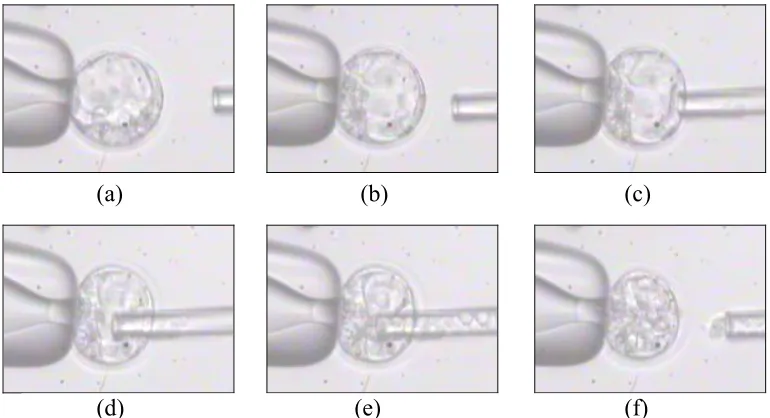
After the blastocysts and ES cells settle at the bottom of the Petri dish, ten to fifteen
cells are selected and drawn into the injection pipette. The blastocyst to be injected is then
immobilized by applying a vacuum pressure at the holding pipette. It is then carefully
rotated (with the help of the injection pipette) until the inner cell mass (ICM) is directly
opposite to the injection point, as shown in Fig. 1.4(a). Following the blastocyst
immobilization, the loaded injection pipette is introduced into the blastocoel cavity, and
the ES cells are slowly expelled, as depicted in Fig. 1.4(b). After delivering the ES cells,
the injection pipette is then withdrawn and the process repeated up to 100 times in a given
microinjection session. Finally, the injected embryos are implanted into the uterus of a
pseudo-pregnant mouse for development to term.
(a) (b)
Fig. 1.4. Blastocyst microinjection: (a) the holding pipette immobilizes the embryo; and (b) the injection pipette deposits ES cells in the blastocoel cavity.
1.5.
Contributions Towards Biomanipulation Automation
Even though much of the focus of the bio-robotics research community is currently
ever-growing need for improved consistency and efficiency in this area. This need can only be
satisfied by full process automation; hence this research continued to push towards a fully
automated system by concentrating on the development of a novel system setup for cell
microinjections.
Here, a knowledge-based control system was used as the basis of producing an
automated blastocyst microinjection system. The idea was to learn the task from skilled
users, who have implicit knowledge about the microinjection process that they cannot
articulate. To do this, a framework was created to allow a computer to observe and register
all human actions during semi-automated microinjection experiments.
The developed framework consisted of a semi-automated system that was
teleoperated from a graphical user interface (GUI) running on a desktop computer. The
GUI provided the user with real-time video from the microscope, and received
microinjection control commands through a joystick. This created a work environment
with the feel of a computer game, one that was more ergonomic and comfortable for the
operator. Furthermore, this system constructed a knowledge database by logging the cause
and effect data recorded from the teleoperated microinjection trials.
The developed semi-automated system is described in detail in this work. This
system was tested by a microinjection expert and by two novices, and the experimental
data gathered was used to derive a set of preliminary knowledge-based rules for blastocyst
microinjections. These rules were then encoded in an attempt to fully automate the
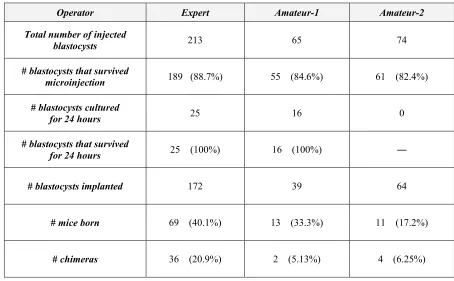
The examination of experimental results obtained with the teleoperated system
showed that both the expert and the amateurs obtained microinjection success rates greater
than 80%, surpassing the typical 40-70% range reported on the literature [4]. Furthermore,
the implantation of the successfully injected blastocysts into surrogate mothers showed that
the blastocysts injected on the semi-automated system were more likely to develop to term
than those injected by experts through the traditional manual method. Therefore, the
semi-automated system developed for blastocyst microinjections was proved effective and easy
to use. Furthermore, the experiments demonstrated that this new system eliminated the
need for extensive training of microinjection operators.
Contributions towards full process automation are also presented in this work,
including the creation of a new system configuration more appropriate for computer
controlled operations; the identification of basic microinjection tasks for automation; and
the design of low and high-level automation algorithms. These developments were tested
through preliminary experimentation and they successfully demonstrated automation by
accomplishing automated blastocysts microinjections. Unfortunately, full process
automation was not achieved in this work due to problems related to the automated
delivery of ES cells. However, automatic microinjections performed with the assistance of
an operator obtained a 75% success rate, showing that the developed system is close to
achieving fully automated microinjection. Consequently, the research presented in this
work shows that full automation of blastocyst microinjection is possible and that it
2.
T
HE
S
EMI
-A
UTOMATED
M
ICROINJECTION
S
YSTEM
The first step towards a full automation of blastocyst microinjections was the
development of a semi-automated system capable of performing this task under the control
of a human operator. The system presented in this chapter is a teleoperated cell injection
system in which the user controls the entire microinjection process through a joystick and a
graphical user interface.
This setup not only provides the operator with a more ergonomic working
environment, but it also allows the controlling computer to capture and register all human
actions during the microinjection experiments. The resulting reactions in the work area are
also observed and registered by the system, and are based on information extracted from
real-time video data. Therefore, this system allows the construction of a knowledge
database from which future intelligent controllers can be developed.
This chapter describes the semi-automated system configuration, the equipment
used, and the software algorithms developed for system control. A description of the
graphical user interface is also provided, highlighting its features and capabilities that
make whole the system easy to operate and capable of reliable experimental data
collection.
2.1.
Main Components
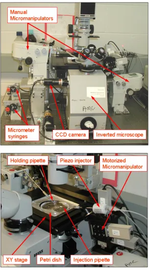
performed under a Zeiss IM35 inverted microscope, which provided the necessary optical
magnification and illumination level for properly imaging the injection area. Images of
that area were captured by a black-and-white CCD camera (LCL-902K, Watec America
Corp.) that was installed on the microscope. The camera provided video feedback to the
system’s controlling computer.
The other major components of the developed system include: 1) two Leitz manual
micromanipulators for positioning of the holding and injection pipettes; 2) one computer
controlled PMM piezo injector; 3) one Siskiyou MX7600R motorized micromanipulator
and its respective driver for high-resolution motion control of the injection needle; and 4)
two Narishige IM-6 micrometer syringes outfitted with motors for computer control of
fluid motions. Later, a motorized XY stage was included as part of the system. This stage
was used to move the petri dish around the microscope’s field of view, see Fig. 2.1.
A desktop computer with a Pentium4® CPU running at 3.2GHz was employed for
processing, control, and for the teleoperated biomanipulations. The computer used a
WinTV-PCI frame grabber card for capturing video, and a Saitek Cyborg Evo Force
2.2.
System Configuration
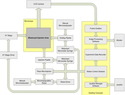
The microinjection system configuration is shown in block diagram form in Fig.
2.2. The figure shows how the user controls the microinjection operation from the
computer station, where he/she interacts with the system through a monitor and a joystick.
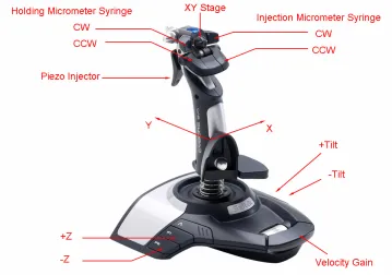
Five devices are independently controlled from the joystick: 1) the micromanipulation
robot for accurate positioning of the injection pipette; 2) the piezo injector used for
blastocyst penetration; 3) the XY stage used to move the Petri dish around the
microscope’s field of view; 4) the micrometer syringe used to produce suction force at the
holding pipette; and 5) the micrometer syringe used to control the dispensing of ES cells
into a blastocyst.
From Fig. 2.2 it can be seen that two devices are used to control the position of the
injection pipette: 1) the manual micromanipulator; and 2) the computer controlled robot.
The manual micromanipulator provides coarse positioning, i.e., large displacements, while
the micromanipulation robot provides fine motion control, i.e., fine displacements. This
robot is controlled using serial commands and provides 3-dimensional motions with 0.1µm
resolution in each direction.
The holding pipette in this system is positioned manually through the left Leitz
micromanipulator. Its position is set when a new Petri dish is placed on the microscope
stage, and is kept fixed throughout the teleoperation procedures. This design was adopted
because blastocyst manipulation was accomplished using a single moving pipette, in this
case the injection pipette. Once a blastocyst was dropped into the injection area, it was
holding pipette suction on, the blastocyst was immobilized for the duration of the injection
cycle. ES cells were injected into the blastocyst after the injection pipette was inside the
blastocoel cavity. The injections were facilitated by the use of the piezo injector.
2.3.
Software Units
The system configuration diagram presented in Fig. 2.2 shows that the processing
software is composed of three main units: 1) the video processing unit; 2) the motion
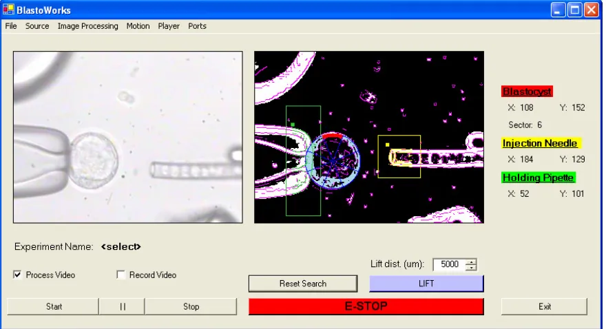
The video processing software unit is responsible for the acquisition, processing
and displaying of video frames. Video frames are acquired from the frame grabber card,
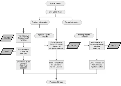
and post-processed to locate the pipettes and any blastocysts. This software unit also
estimates the optimum injection point through the blastocyst’s trophoblast cell layer, and it
displays the original and processed video frames on the computer monitor. A description
of the image processing algorithm used within this module will be given in Chapter 4.
The motion control software unit receives and manages motion commands from the
joystick. Based on the inputs, this unit does all the necessary processing and signal
generation to drive the motion devices via the computer’s serial ports.
The data recording unit observes and records all events taking place in an
experiment into a data file. This unit keeps track of all inputs and outputs of the
micromanipulator system. It also records the positions of the injection and holding
pipettes, the blastocyst position, and a continually updated estimate of the optimum
blastocyst injection point. The goal of this data collection system is to create a database
from which a knowledge-based controller will be developed to automate the blastocyst
microinjection process. This knowledge-based controller is desired for three reasons: 1) it
can be encoded to see how it performs as an automated controller, 2) it can be used as a
standard controller, against which other machine-learned or intelligent controllers can be
A small section of an experimental data file is shown in Fig. 2.3. The figure shows
that the data recording unit creates text files in which experimental information is encoded
with description characters followed by the corresponding numerical values and time
stamps. Using this format, everything that happens during an experiment can be recorded
for later use. The meaning of the description characters are given in Table 2.1 and Table
2.2.
Table 2.1. Description characters.
Character Numerical Values Description
b [bx] [by] Blastocyst coordinates
s [s] Selected injection sector
h [hx] [hy] Holding pipette coordinates
i [ix] [iy] Injection pipette coordinates
m [axis] [amount] Motion command
p1 [byte] Command byte 1: micrometer syringes
p2 [byte] Command byte 2: micrometer syringes and piezo injector
…
h 118 127 20:08:19.64 m 0 450 20:08:19.73 m 1 450 20:08:19.89 b 85 119 20:08:19.92 i 213 126 20:08:19.92 p1 64 20:08:20.01 p2 1 20:08:20.01 …
2.4.
Robot Control
The control of the micromanipulation robot is performed through the motion
control software unit, which has subroutines solely dedicated to the processing of joystick
commands related to this task. This ensures that user commands are formatted and
submitted to the robot driver in real-time, thus guaranteeing precise motion control.
During blastocyst micromanipulation, operators often use fast motions to quickly
adjust the position and orientation of blastocysts for injection. In contrast, small and
precise motions are used during the actual injection phase. Therefore, the
micromanipulator robot used was selected based on its speed and accuracy.
The Siskiyou MX7600R motorized micromanipulator was the robot selected to the
developed microinjection system. It is able to move at “very fast” speeds, reaching up to
1.7 mm/s of linear velocity while still maintaining its accuracy thanks to built-in encoders.
The robot’s minimum controllable displacement is 0.1 µm, which is enough for the
blastocyst micromanipulation tasks since the smallest cells involved in the process (the ES
cells) typically measure 10 µm in diameter.
Table 2.2. Command bytes for the micrometer syringes and piezo injector.
Bit # 7 6 5 4 3 2 1 0
Command byte 1
Collector
CCW Collector CW Dispenser CCW Dispenser CW Holder CCW Holder CW Injector CCW Injector CW
Command
byte 2 OUT 4 OUT 3 OUT 2
The fast displacements and the precise motions required for the
micromanipulations are achieved by applying an exponential function to the analog
commands generated by the joystick, as shown in Fig. 2.4. This way the operator can
command small or large displacements without changing any of the system settings.
Furthermore, the joystick’s slider bar is used as a velocity gain control to allow for even
faster motions, so the operator can easily increase the velocities directly from the joystick.
-250 -200 -150 -100 -50 0 50 100 150 200 250
-5000 -4000 -3000 -2000 -1000 0 1000 2000 3000 4000 5000
Joystick Input
Dis
ta
nc
e Command (microns)
Fig. 2.4. Exponential function applied to the joystick commands. Modifying the linear values generated by the joystick allows for fast displacement and for small and precise motions without
changing any of the system’s settings.
⎟⎟ ⎠ ⎞ ⎜⎜ ⎝ ⎛ − = 592 500 exp 10 )
(J J
2.5.
XY Stage
The developed semi-automated blastocyst microinjection system incorporates an
XY stage to move the petri dish around during the procedures. This is useful because it
allows the collection of ES cells to be conducted from the computer station, thus
permitting the operator to remotely carry out the entire microinjection procedure. The
operations performed at the microscope stage are restricted to the initial setup of the
working wells and the alignment of the pipettes. After that all operations are performed
from the computer station using the joystick and keyboard.
The ability to remotely load the injection pipette and carry out entire procedures
saves time when multiple microinjections are performed by avoiding trips to the
microscope stage. This would be necessary without the XY stage because the ES cells are
located separately from the injection site, and because they are typically loaded into the
injection pipette prior to every three or four blastocyst injections.
Another advantage of having an XY stage comes from the fact that several working
wells containing blastocyst and ES cells may be put on the same petri dish, as shown in
Fig. 2.5. Consequently, there is a need to move each of those sites to the microscope’s
field of view.
The installed XY stage presents a step resolution of 10 µm in each direction, and
can move at speeds of up to 45 mm/s. A custom controller board drives this stage, and
also provides storage area for the coordinates of 20 locations, allowing for instantaneous
motion between different sites. This feature speeds-up multiple microinjection tasks by
![Fig. 1.1. Manual micromanipulator made by Leica Microsystems. Picture reprinted with permission from [69]](https://thumb-us.123doks.com/thumbv2/123dok_us/1764644.1226923/19.612.196.430.310.513/fig-manual-micromanipulator-leica-microsystems-picture-reprinted-permission.webp)
![Tetraaquabis[2,3 bis(5 methyl 1,3,4 thiadiazol 2 ylsulfanylmethyl)quinoxaline]nickel(II) bis(perchlorate) acetone disolvate](data:image/gif;base64,R0lGODlhAQABAIAAAP///wAAACH5BAEAAAAALAAAAAABAAEAAAICRAEAOw==)