DS2000
Software Manual
Part No. 80000SWG02 Issue 1-0, October 1999 010000/101499
This manual has been developed by Nitsuko America. It is intended for the use of its customers and service personnel, and should be read in its entirety before attempting to install or program the system. Any comments or suggestions for improving this manual would be appreciated. Forward your remarks to:
Nitsuko America, Telecom Division 4 Forest Parkway Shelton, CT 06484 Attention: Manager, Technical Publications
http://www.nitsuko.com
Nothing contained in this manual shall be deemed to be, and this manual does not constitute, a warranty of, or representation with respect to, any of the Equipment covered. This manual is subject to change without notice and Nitsuko America has no obligation to provide any updates or corrections to this manual. Further, Nitsuko America also reserves the right, without prior notice, to make changes in equipment design or components as it deems appropriate. No representation is made that this manual is complete or accurate in all respects and Nitsuko America shall not be liable for any errors or omissions. In no event shall Nitsuko America be liable for any incidental or consequential damages in connection with the use of this manual. This document contains proprietary information that is protected by copyright. All rights are reserved. No part of this document may be photocopied or reproduced without prior written consent of Nitsuko America.
Chapter 1 Features . . . 1
Introduction . . . .1
Initial System Startup. . . .6
Charts and Illustrations . . . .8
2-OPX Module . . . .17
Account Codes . . . .18
Alphanumeric Display . . . .19
Analog Communications Interface (ACI) . . . .20
Alternate Attendant . . . .21
Attendant Call Queuing . . . .22
Attendant Position . . . .24
Automatic Call Distribution (ACD). . . .28
Automatic Fault Reporting. . . .29
Automatic Handsfree . . . .30
Automatic Ring Down . . . .33
Automatic Route Selection . . . .34
Background Music . . . .35
Barge In (Intrusion) . . . .37
Battery Backup. . . .39
Call Coverage Keys . . . .40
Call Forwarding . . . .43
Call Forwarding, Off-Premise . . . .46
Call Forwarding Cancel . . . .47
Call Timer . . . .48
Call Waiting / Camp-On . . . .51
Callback . . . .54
Caller ID. . . .57
Central Office Calls, Answering . . . .58
Central Office Calls, Placing . . . .63
Check Key . . . .71
Class of Service . . . .73
Computer Telephony Integration . . . .78
Conference . . . .79
Data Communications Interface (DCI) . . . .81
Delayed Ringing . . . .82
Dial Number Preview. . . .84
Dial Tone Detection . . . .86
Direct Inward Dialing . . . .87
Direct Inward Line . . . .88
Direct Inward System Access (DISA) . . . .94
Direct Station Selection (DSS) . . . .95
Direct Station Selection (DSS) Console . . . .98
Direct Trunk Access. . . .106
Directed Call Pickup . . . .108
Directory Dialing . . . .110
Distinctive Ringing, Tones and Flash Patterns . . . .113
Do Not Disturb. . . .114
Door Box . . . .116
E911 Compatibility . . . .117
Equal Access Compatibility. . . .118
Extended Ringing. . . .119
Extension Hunting . . . .121
External Alerting Devices . . . .131
Flash . . . .132
Flexible Numbering Plan . . . .134
Forced Trunk Disconnect. . . .137
Group Call Pickup . . . .139
Group Listen . . . .142
Group Ring. . . .144
Handsfree and Handsfree Answerback . . . .150
Headset Compatibility . . . .154
Hold . . . .156
Hotline . . . .160
Interactive Soft Keys . . . .163
Intercom . . . .165
Key Ring . . . .170
Last Number Redial . . . .174
Line Keys . . . .176
Loop Keys . . . .179
Meet-Me Conference . . . .184
Message Waiting . . . .187
Microphone Mute. . . .190
Monitor / Silent Monitor . . . .192
Multiple Directory Numbers . . . .194
Music On Hold. . . .195
Names for Extensions and Trunks . . . .198
Night Service / Night Ring. . . .200
Off-Hook Signaling . . . .205
Off-Premise Extensions / On-Premise SLT Extensions. . . .207
One-Touch Keys . . . .213
Paging. . . .214
Park . . . .218
PBX/Centrex Compatibility . . . .222
Prime Line Preference . . . .223
Privacy . . . .226
Privacy Release Groups . . . .228
Private Line . . . .231
Programmable Function Keys . . . .235
Pulse to Tone Conversion . . . .240
Removing Trunks and Extensions From Service. . . .242
Repeat Redial . . . .244
Reverse Voice Over . . . .245
Ring Groups . . . .248
Ringdown Extension . . . .249
Ringing Line Preference . . . .251
Save Number Dialed . . . .254
Selectable Display Messaging . . . .256
Single Line Telephones . . . .260
Soft Keys . . . .261
Silent Monitor . . . .262
Speed Dial . . . .263
Split (Alternate) . . . .272
Station Instruments . . . .274
Station Message Detail Recording . . . .277
Station Overflow . . . .283
System Diagnostics . . . .284
System Identification . . . .285
System Programming Backup and Restore . . . .287
System Programming List . . . .289
System Programming Password Protection . . . .291
System Timers . . . .292
System Timers, Stations. . . .295
System Timers, Trunks . . . .300
Tandem Trunking / Unsupervised Conference . . . .307
Tenant Service . . . .310
Tie Lines . . . .311
Time and Date . . . .312
Toll Restriction . . . .314
Toll Restriction Override . . . .322
Traffic Management Report (TMS) . . . .323
Transfer . . . .324
Trunk Group Routing. . . .329
Trunk (Line) Queuing / Trunk Callback . . . .332
Trunk Groups . . . .335
Trunk Timers . . . .338
Voice Announce Unit (VAU) . . . .339
Voice Mail . . . .340
Voice Over . . . .350
Voice Prompting Messages . . . .352
Volume Controls . . . .353
Year 2000 Compliance. . . .355
Chapter 2 Programming . . . 357
Introduction to Programming. . . .357
Before You Start Programming . . . .357
0100 - Class of Service . . . .362
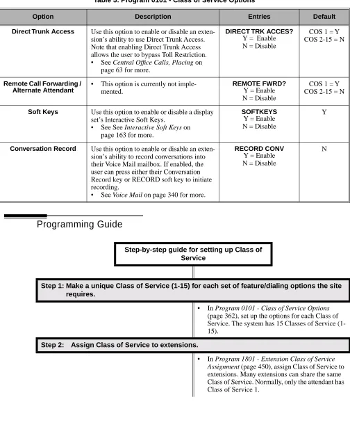
0101 - Class of Service Options . . . .362
0200 - Tenant Options . . . .367
0201 - Tenant Option Programming . . . .367
0300 - System Options . . . .370
0301 - System Options (Part 1) . . . .370
0302 - System Identification . . . .372
0400 - Timers . . . .375
0401 - System Timers . . . .375
0402 - Trunk Timers . . . .378
0403 - Station Timers . . . .386
0404 - Analog Station Timers . . . .389
0500 - System Numbering . . . .392
0501 - Numbering Plan . . . .392
0504 - Trunk Port Extension Numbers . . . .396
0505 - Station Port Extension Numbers . . . .398
0506 - ACI/CPU Analog Port Extension Numbers and Names . . . .400
0507 - DCI Extension Numbers and Names . . . .401
0510 - ACD/UCD Master Extension Numbers and Names . . . .402
0511 - Ring Group Master Extension Numbers and Names . . . .404
0600 - Toll Restriction . . . .406
0601 - Toll Restriction Options . . . .406
0700 - Analog Communications Interface (ACI). . . .413
0701 - Analog Communications Interface (ACI) Options . . . .413
0800 - Display Messages . . . .414
0801 - Selectable Display Messages . . . .414
1000 - Trunk Programming . . . .416
1001 - Trunk Port Description . . . .416
1002 - Trunk Groups . . . .424
1003 - Trunk Options. . . .426
1004 - Loop Group Assignment . . . .430
1100 - Speed Dial. . . .431
1101 - System Speed Dial Numbers . . . .431
1102 - Speed Dial Block Assignment . . . .433
1500 - Access Level . . . .435
1501 - Extension Access Level . . . .435
1700 - Key Programming. . . .436
1701 - Programmable Function Key Assignments . . . .436
1702 - Personal Speed Dial . . . .441
1703 - DSS Key Assignment . . . .443
1704 - DSS Console Key Assignment. . . .444
1800 - Extension Options. . . .449
1801 - Extension Port Description. . . .449
1802 - Extension Options (Part 1) . . . .455
1803 - Extension Line Access Assignments . . . .461
1804 - Extension Trunk Group Access . . . .464
1805 - Ring Assignments. . . .466
1806 - . . . .468
1807 - Extension Options (Part 2) . . . .469
9800 - System Utilities, Part 1 . . . .472
9801 - Copy Command . . . .472
9900 - System Utilities, Part 2 . . . .474
9901 - Reset Station Port . . . .474
9902 - Reset Trunk Port. . . .475
9903 - System and PCB Reset . . . .476
9904 - Side Tone Test . . . .477
9905 - Password. . . .478
9906 - Database Save. . . .479
9907 - Database Load . . . .481
Introduction
Chapter 1
Features
Introduction
Introduction
Before Reading This Section
This section provides detailed information on the system’s features. If you don’t know what the var-ious features are, review the Table of Contents for this section and the manual’s Index. After reviewing, turn back to this section for the specifics.
Using This Section
The features in this section are in alphabetical order, like a dictionary. This section subdivides each feature definition into headings as follows:
Description
Read Description to get an overview of the feature. Along with the feature’s description are the Conditions and Default Setting. Conditions provides the feature’s operational limits (if any). Default Setting outlines how the feature works with the default (factory installed) Programming List. When initially installed, the system uses the default setting. For specific default settings on each program, refer to the chart at the end of this manual.
In each feature description there are two icons which provide additional essential information about the feature:
This is Feature Benefit icon. Read this text to find out how the feature can help co-worker’s become more productive and streamline company-wide communications.
Introduction
Programming Guide
The Programming Guide is an easy-to-use chart that guides you step-by-step through programming the feature. If you’re not sure how to set up a feature, start first with the Programming Guide.
Programming List
Programming List explains the system Programming List that lets you customize the feature. Some features require Programming List; others don’t. If you decide to customize a feature, use Section 2 to enter the change into the system.
Other Related Features
Read this part to learn how the feature interacts with other features.
Feature Operation
Introduction
System Configuration
The total number of components you can install and connect to your system depends on power sup-ply capacity and the System Load Factor. Use the table below and the following steps to calculate the System Load Factor.
To check your system configuration:
1. Indicate the quantity for each item installed in the Qty column.
2. For each item, multiply the Qty times the Load Factor and enter the value in the Total Load column.
3. Add all the values in the Total Load column and enter the value in row 1.
4. Determine the System Load Factor capacity of the power supplies installed in your system and enter the total in row 2.
A 4-Slot Cabinet can have only 1 power supply. An 8-Slot Cabinet can have up to 3 power supplies. You cannot have more than two 16DSTU PCBs per power supply. 5. Compare the entry in row 2 to your entry in row 1. Row 1 must always be equal to or less
than the entry in row 2.
Notes for 4-Slot Cabinets with Fixed Slot Software
• If your 4-slot cabinet uses fixed slot software, you can plug DSTU PCBs only into slots CN1 and CN2.
• You can plug an ASTU PCB only into slot CN2 (in place of the second DSTU PCB). • Install ATRU PCBs only into slots CN3 and CN4.
• System Load Factor in fixed slot systems is only an issue if you have DSS Consoles and 2-OPX Modules installed.
• The Release Notes that came with your system indicate if it uses fixed slot software. • Check your system’s Hardware Manual for more installation details.
• Maximum configuration for 4-slot cabinets with fixed slot software is 16 trunks and 32 extensions.
Notes for 4-Slot and 8-Slot Cabinets with Universal Slot Software
• A 4-slot cabinet with universal slot software cannot connect more than 40 extensions, regardless of System Load Factor.
• A 4-slot cabinet with universal slot software cannot connect more than 24 trunks, regardless of System Load Factor.
• An 8-slot cabinet with universal slot software cannot connect more than 96 extensions, regardless of System Load Factor.
• An 8-slot cabinet with universal slot software cannot connect more than 48 trunks, regard-less of System Load Factor.
Introduction
Typical 4-Slot Cabinet Universal Slot Software Configurations
The following configurations do not apply to fixed slot software. Refer to the Release Notes that came with your system to find out if you have fixed slot software.
● 16 x 32 (16 trunks and 32 digital extensions)
Recommended for sites with no Voice Mail and high trunk usage. ● 24 x 16 (24 trunks and 16 digital extensions)
Recommended for sites with no Voice Mail and very high trunk usage. ● 8 x 16 x 16 (8 trunks, 16 digital extensions and 16 analog extensions)
Recommended for sites with Voice Mail, normal trunk usage and high analog extension usage.
● 16 x 8 x 8 (16 trunks, 8 digital extensions and 8 analog extensions)
Recommended for sites with Voice Mail, high trunk usage and high analog extension usage. ● 8 x 32 x 8 (8 trunks, 32 digital extensions and eight analog extensions)
Recommended for sites with Voice Mail, normal to low trunk usage and low analog extension usage.
System Load Factor Calculations
Item Load Factor Qty Total Load
16DSTU PCB 16
4ASTU PCB 8
8ASTU PCB 12
110-Button DSS Console 2
24-Button DSS Console 1
2-OPX Module 3
1. Total load for this configuration:
Introduction
User-Programmable Features
Extension users may be able to customize certain features. These are the User-Programmable Fea-tures and include:
● Call Coverage Key Ringing
● Group Call Pickup Key Ringing
● Line Key Ringing
● Intercom Voice Announce Mode
● Speed Dial
Table 1: User-Programmable Features
For this feature Dial this code When you are
Call Coverage # + R C (72) + Press Call Coverage key repeatedly to
select ringing mode
Setting the ringing mode for your extension’s Call Coverage
keys
Group Call Pickup # + R G (74) + Press Group Call Pickup key repeatedly
to select ringing mode
Setting the ringing mode for your extension’s Group Call
Pickup keys
Line Keys # + R L (75) + Press Line Key repeatedly to select
ringing mode
Setting the ringing mode for your extension’s line keys
Intercom # + I V (48) Enabling voice-announce for your incoming Intercom calls
# + I R (47) Enabling ringing for your incoming Intercom calls
Speed Dial ICM + ## + 200-299 Programming System Speed Dial numbers
ICM + ## + 701-720 Programming Personal Speed Dial numbers
Initial System Startup
Initial System Startup
Initial Startup Programming
Initial Startup Programming (Page 1 of 2)
Step 1: Enter the programming mode.
• From any display telephone:
Press ICM + #*#* + Password + HOLD. • The default system passwords are:
Installer (level 3) = 372000
System Administrator 2 (level 2) = 9999 System Administrator 3 (level 1) = 0000
Step 2: Assign the correct circuit type to your installed trunks.
• In Program 1001 - Trunk Circuit Type (page 416), enter the correct circuit type for each installed trunk:
00 = Uninstalled 51 = Loop start DTMF 52 = Loop start DP
Step 3: Assign the correct circuit type to your installed extensions.
• In Program 1801 - Extension Circuit Type (page 449), enter the correct circuit type for each installed extension:
00 = Uninstalled 01 = 22-Button Standard 02 = 22-Button Display 06 = 34-Button Display 09 = 34-Button Super Display 15 = Analog station
21 = 2OPX
Step 4: By default, each extension has full access to each trunk. Do you want to change this assignment?
• For each extension in Program 1803 - Extension Line Access Assignments (page 461), assign the access options for each trunk. The options are:
0 = No access 1 = Incoming only 2 = Outgoing only 3 = Full access
• Use Program 9801 - Copy Command (page 472), to simplify your programming.
If yes
Initial System Startup
• In Program 1803 - Extension Line Access Assign-ments (page 461), make no changes from the default assignments.
Step 5: By default, each extension rings for every incoming trunk call. Do you want to change this assignment?
• For each extension in Program 1805 - Ring Assignments (page 466), assign ringing for each trunk. The options are:
1 = Lamp only (day and night) 2 = Ringing day and night
3 = Night Ring only, lamp during the day 4 = Delay ring day and night
• Use Program 9801 - Copy Command (page 472), to simplify your programming.
• The system attendant (extension 300) can put these trunks in the night mode by pressing their preassigned Night Key (key 11).
• For each extension in Program 1805 - Ring Assignments (page 466), make no changes from the default assignments.
Step 6: Does your system have Voice Mail?
• Turn to Voice Mail on page 340 and review the required Voice Mail programming.
• Go to the next step.
Step 7: Do you want to change the default system passwords?
• In Program 9905 - Password (page 478), change the passwords from their default settings.
• In Program 9905 - Password (page 478), do not change the passwords from their default settings.
Step 8: Do you want to return the system to its factory installed (default) programming?
• In Program 9999 - System Initialization (page 482), reinstate the factory installed pro-gramming. This erases all your programming
and returns the system to its initial default set-tings.
• In Program 9999 - System Initialization (page 482), do not reinstate the factory installed programming.
Initial Startup Programming (Page 2 of 2)
If no If yes If no If yes If no If yes If no If yes If no
Charts and Illustrations
Charts and Illustrations
Table 2: Dial Codes (by Number)
For this feature Dial this code When you are Also use Function Key
Call Forwarding *30 Canceling Call Forwarding at an extension
*32 + Extension or 0 (for operator)
Enabling Call Forwarding Busy/No Answer
*34 + Extension or 0 (for operator)
Enabling Call Forwarding All Calls
*36 + Extension or 0 (for operator)
Enabling Call Forwarding No Answer
Selectable Display
Charts and Illustrations
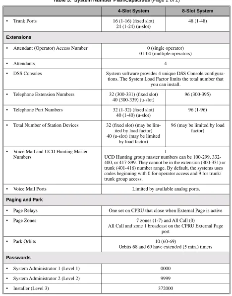
Table 3: System Number Plan/Capacities (Page 1 of 2)
4-Slot System 8-Slot System
System Options
• Classes of Service 1-15
• Conference 32 simultaneous users in Conference (total of all Conferences system-wide)
8 simultaneous Conferences maximum 8 parties maximum in any one Conference
• Extension Hunting (ACD/UCD) Master Numbers
8
• Extension Hunting Groups 8 (1-8)
• Group Call Pickup Groups 8 (1-8, 0 = unassigned)
• Privacy Release Groups 16 (1-16, 0 = unassigned)
• Speed Dial, Personal 20 bins at each extension (701-720)
See Speed Dial (page 263) for additional information on Speed Dial capacities.
• Speed Dial. System 10 (20-29), 100 (200-299), 1000 (2000-2999) See Speed Dial (page 263) for additional information on
Speed Dial capacities.
• Tenant Groups 1
• Timeslots Non-blocking
• Toll Restriction Levels 7 (1-7, 0 = no restriction)
Trunks
• Direct Trunk Access Codes 401-416 (fixed slot) 401-424 (u-slot)
401-448
• Line Dial Up Codes #901-#916 (fixed slot) #901-#924 (u-slot)
#901-#948
• Ring Groups 8 (1-8)
0 = No assignment
Ring Group master numbers can be 100-299, 332-400, or 417-899. They cannot be in the extension (300-331) or trunk (401-416) number range. By default, the systems uses codes beginning with 0 for operator access and 9 for trunk/trunk
group access.
• Trunk Group Access Codes 90-98
Charts and Illustrations
• Trunk Ports 16 (1-16) (fixed slot)
24 (1-24) (u-slot)
48 (1-48)
Extensions
• Attendant (Operator) Access Number 0 (single operator) 01-04 (multiple operators)
• Attendants 4
• DSS Consoles System software provides 4 unique DSS Console configura-tions. The System Load Factor limits the total number that
you can install.
• Telephone Extension Numbers 32 (300-331) (fixed slot) 40 (300-339) (u-slot)
96 (300-395)
• Telephone Port Numbers 32 (1-32) (fixed slot) 40 (1-40) (u-slot)
96 (1-96)
• Total Number of Station Devices 32 (fixed slot) (may be lim-ited by load factor) 40 (u-slot) (may be limited
by load factor)
96 (may be limited by load factor)
• Voice Mail and UCD Hunting Master Numbers
1
UCD Hunting group master numbers can be 100-299, 332-400, or 417-899. They cannot be in the extension (300-331) or trunk (401-416) number range. By default, the systems uses codes beginning with 0 for operator access and 9 for trunk/ trunk group access.
• Voice Mail Ports Limited by available analog ports.
Paging and Park
• Page Relays One set on CPRU that close when External Page is active
• Page Zones 7 zones (1-7) and All Call (0)
All Call and zone 1 broadcast on the CPRU External Page port
• Park Orbits 10 (60-69)
Orbits 68 and 69 have extended (5 min.) timers
Passwords
• System Administrator 1 (Level 1) 0000
• System Administrator 2 (Level 2) 9999
• Installer (Level 3) 372000
Table 3: System Number Plan/Capacities (Page 2 of 2)
Charts and Illustrations
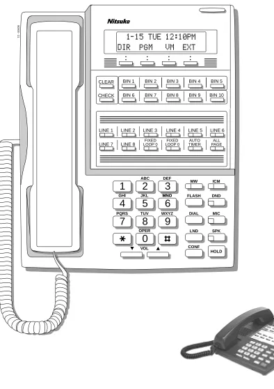
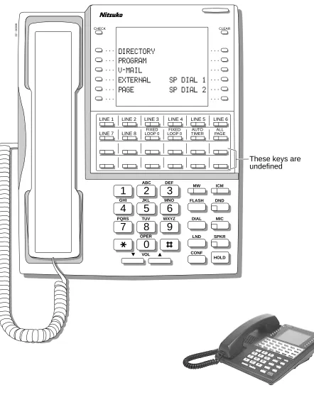
Figure 1: 22-Button Display Telephone
1
2
3
4
5
6
7
8
9
0
ABC DEF
MW ICM
FLASH DND
DIAL MIC
LND SPK
CONF HOLD GHI JKL MNOMNO
PQRS TUV
OPER
VOL
WXYZ
CLEAR CHECK
80000 - 21
LINE 1 LINE 2 LINE 3 LINE 4 LINE 5 LINE 6 LINE 7 LINE 8 LOOP 0FIXED
FIXED LOOP 0
AUTO TIMER
ALL PAGE
Charts and Illustrations
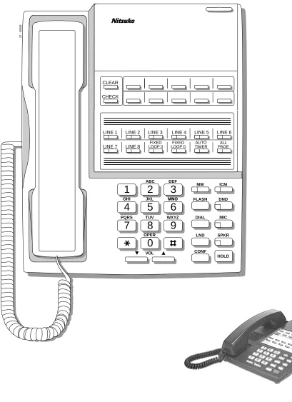
Figure 2: 22-Button Standard Telephone
1
2
3
4
5
6
7
8
9
0
ABC DEF
MW ICM
FLASH DND
DIAL MIC
LND SPKR
CONF HOLD GHI JKL MNOMNO
PQRS TUV
OPER
VOL
WXYZ
CLEAR
CHECK
80000 - 22
LINE 1 LINE 2 LINE 3 LINE 4 LINE 5 LINE 6
Charts and Illustrations
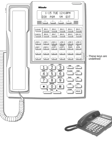
Figure 3: 34-Button Display Telephone
1
2
3
4
5
6
7
8
9
0
ABC DEF
MW ICM
FLASH DND
DIAL MIC
LND SPK
CONF HOLD GHI JKL MNOMNO
PQRS TUV
OPER
VOL
WXYZ
CLEAR
CHECK
80000 - 10
LINE 1 LINE 2 LINE 3 LINE 4 LINE 5 LINE 6
LINE 7 LINE 8
BIN 1 BIN 2 BIN 3 BIN 4 BIN 5
BIN 6 BIN 7 BIN 8 BIN 9 BIN 10
These keys are undefined FIXED
Charts and Illustrations
Figure 4: 34-Button Super Display Telephone
1
2
3
4
5
6
7
8
9
0
ABC DEF
MW ICM
FLASH DND
DIAL MIC
LND SPKR
CONF HOLD
GHI JKL MNO
PQRS TUV
OPER
VOL
WXYZ
80000 - 23
CHECK CLEAR
LINE 1 LINE 2 LINE 3 LINE 4 LINE 5 LINE 6 LINE 7 LINE 8
These keys are undefined FIXED
Charts and Illustrations
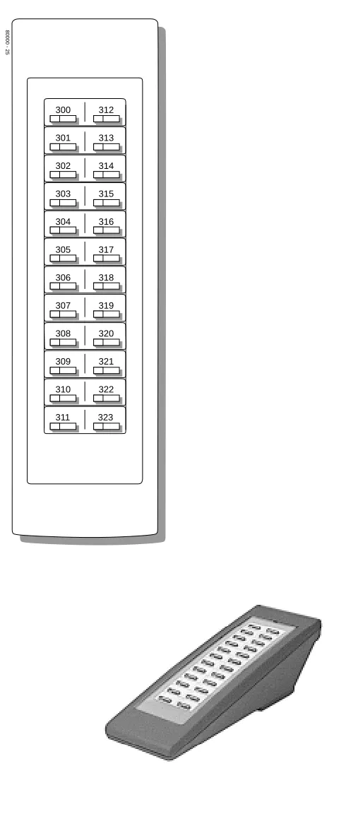
Figure 5: 24-Button DSS Console
80000 - 25
300 312
301 313
302 314
303 315
304 316
305 317
306 318
307 319
308 320
309 321
310 322
Charts and Illustrations
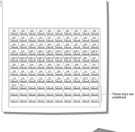
Figure 6: 110-Button DSS Console
80000 - 24
300 301 302 303 304 305 306 307 308 309
310 311 312 313 314 315 316 317 318 319
320 321 322 323 324 325 326 327 328 329
330 331 LINE 1 LINE 2 LINE 3 LINE 4 LINE 5 LINE 6 LINE 7 LINE 8
202 203 204 205 206 207 208 209 701 702
703 704 705 706 707 708 709 710 711 712
713 714 715 716 717 718 719 720 PG 0 PG 1
PK 0 PK 1
These keys are undefined
2-OPX Module
2-OPX Module
Description
Account Codes
Account Codes
Description
Alphanumeric Display
Alphanumeric Display
Description
The 22- and 34-Button Display Telephones have a two-line, 20-character per line alphanumeric dis-play. The first line displays the date and time (while idle) and feature status messages. The second line displays the Soft Key definitions.
The 34-Button Super Display Telephone has an eight-line, 20-character per line alphanumeric dis-play. The first line displays the data and time (while idle) and feature status messages, just like the 22- and 34-Button Display Telephones. Lines 2-8 are the comprehensive Super Display Telephone soft key definitions.
● To learn more about the display telephones, see 22-Button Display Telephone on page 11, see 34-Button Display Telephone on page 13 and see 34-Button Super Display Telephone on page 14.
● To learn more about the Soft Keys, see Soft Keys on page 261.
Conditions None
Default Setting
Enabled for all display telephones.
Programming Guide
None
Programming List
None
Other Related Features
Soft Keys (page 261)
The interactive Soft keys provide users with intuitive access to the telephone’s features. Volume Controls (page 353)
While a feature is active, pressing VOL ▲ and VOL ▼ adjusts the volume of the active feature.
Feature Operation
Refer to the individual features for feature operation.
The Alphanumeric Display messages help the display telephone user process calls, identify callers and customize features.
Analog Communications Interface (ACI)
Analog Communications Interface (ACI)
Description
Alternate Attendant
Alternate Attendant
Description
Attendant Call Queuing
Attendant Call Queuing
Description
An unlimited number of callers can queue for the attendant. The callers hear ringback while they wait for the attendant to answer — not busy tone. If you have the attendant as the overflow destina-tion for Direct Inward Lines, for example, unanswered DILs will “stack up” at the attendant until they are answered
Operator Call Key
The last programmable key on an attendant telephone is permanently assigned as an Operator Call Key. When the operator has Intercom calls waiting to be answered, the calls queue under this key. The key winks (on) when calls are queued.
The Operator Call Key is a permanent assignment for all extensions assigned as operators. You can-not change this assignment. Attendant Call Queuing is a permanent, non-programmable feature.
Conditions None
Default Setting Enabled
Programming Guide
None
Programming List
None
Other Related Features
Attendant Position (page 24) Assign system attendants. Off-Hook Signaling (page 205)
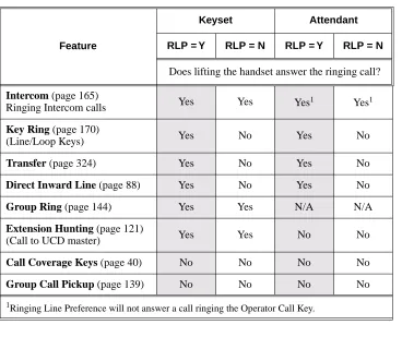
The Operator Call Key activates off-hook signaling. Ringing Line Preference (page 251)
Ringing Line Preference will not answer a call ringing the Operator Call Key. Voice Mail (page 340)
● TRF transfers to the attendant from the Voice Mail Automated Attendant flash the Opera-tor Call key and the Ring IndicaOpera-tor lamp. The call does not flash a line/loop key. (Note that Ringing Line Preference will not pick up a call ringing the attendant’s Call Queue key.) ● UTRF transfers to the attendant from the Voice Mail Automated Attendant flash the
trunk’s line/loop key and the Ring Indicator lamp. LCCPU 01.00.00 Available.
Attendant Call Queuing
Feature Operation
To answer a call flashing the Operator Call Key:
1. Press the flashing Operator Call Key.
Attendant Position
Attendant Position
Description
The attendant is the focal point for call procesing within the system. The system can have up to four attendants. In addition to the features of a standard keyset, the attendant also has the following unique capabilities (refer to the respective feature for details):
● Attendant Call Queuing (page 22)
Incoming Intercom calls from co-workers queue for the attendant. The callers never hear busy tone.
● Barge In (Intrusion) (page 37)
The attendant can break into another extension user’s established call. This option is enabled in the attendant’s Class of Service (COS 1).
● Direct Trunk Access (page 106)
Direct Trunk Access lets the attendant user dial a code to access an individual trunk. This option is enabled in the attendant’s Class of Service (COS 1).
● Forced Trunk Disconnect (page 137)
In an emergency, the attendant can release (disconnect) another user’s active trunk call. This option is enabled in the attendant’s Class of Service (COS 1).
● Night Service / Night Ring (page 200)
An attendant with a Night key can put the system in the night mode. This option is enabled in the attendant’s Class of Service (COS 1).
● Removing Trunks and Extensions From Service (page 242)
The attendant can remove problem trunks from service —then return them to service once the problem is corrected. This option is enabled because the attendant has Direct Trunk Access enabled in their Class of Service (COS 1).
● Trunk (Line) Queuing / Trunk Callback (page 332)
The attendant can Camp On (queue) for a busy trunk. This option is enabled in the attendant’s Class of Service (COS 1).
The attendant should use a 34-Button Display or 34-Button Super Display Telephone. In addition, most attendants should find a 24-Button or 110-Button Direct Station Selection (DSS) Console helpful when processing calls.
Conditions
Ringing Line Preference will not pick up a call ringing the attendant’s Call Queue key.
Default Setting
The system has one operator assigned to extension 300. LCCPU 01.00.00 Available.
Attendant Position
Programming Guide
Step-by-step guide for setting up Attendant Position
Step 1: Install a 34-Button Display or 34-Button Super Display telephone for the attendant.
• A 24-Button or 110-Button DSS Console will also help the attendant process calls more quickly.
Step 2: Should the system have more than one attendant?
• In Program 0301 - Number of Operators (page 370), enter 2-4.
• In Program 0301 - Operator 1 Extension (page 370), Program 0301 - Operator 2 Exten-sion (page 370), Program 0301 - Operator 3 Extension (page 370), and Program 0301 - Oper-ator 4 Extension (page 370), assign the operOper-ator extensions.
• In Program 1802 - Extension’s Operator (page 457), assign an operator to each extension.
• In Program 0301 - Number of Operators (page 370), enter1.
• In Program 0301 - Operator 1 Extension (page 370), assign the system operator’s exten-sion (normally 300).
• In Program 1802 - Extension’s Operator (page 457), assign each extension to the operator (normally 300).
Step 3: While busy on a call, should the attendant be audibly notified of incoming calls?
• Program 1802 - Off-Hook Signaling for CO Calls (page 456), at the attendant’s extension enter 1 for Call Waiting beeps, 2 for off-hook ringing.
• Program 1802 - Off-Hook Signaling for CO Calls (page 456), enter 0 for the attendant’s extension.
Step 4: Should the first digit an extension user dials to reach an operator be 0 (e.g., 0 for single operator systems, 01-04 for multiple operator systems)?
• In Program 0501 - Digit 0 Options (page 392), be sure this option is left at its default setting (Func-tion Type = 1 and Expected Digits = 2).
• In Program 0501 - Digit 0 Options (page 392), exchange the digit 0 settings with the new digit.
Attendant Position
Programming List
Note: Designating an extension as an operator in Program 0301 automatically assigns Class of Service 01 to that extension. If you change your operator setup and make an operator a “normal” extension, be sure to go back and manually reassign a new Class of Service (2-15) to that extension. Note that the attendant’s Class of Service options are fully customizable.
Program 0301 - Number of Operators (page 370) Specify the number of operators in the system (1-4). Program 0301 - Operator 1 Extension (page 370)
Assign the 1st operator’s extension number. Be sure you have entered the correct number in the Number of Operators option above.
Program 0301 - Operator 2 Extension (page 370)
Assign the 2nd operator’s extension number. Be sure you have entered the correct number in the Number of Operators option above.
Program 0301 - Operator 3 Extension (page 370)
Assign the 3rd operator’s extension number. Be sure you have entered the correct number in the Number of Operators option above.
Program 0301 - Operator 4 Extension (page 370)
Assign the 4th operator’s extension number. Be sure you have entered the correct number in the Number of Operators option above.
Program 0501 - Digit 0 Options (page 392)
Assign the digit(s) the system will use for operator access (normally 0 and 01-04). Do not change the Expected Digits entry for the digit 0.
Program 1802 - Extension’s Operator (page 457)
Assign the extension’s operator (300-331). This is the co-worker the extension user reaches when they dial 0.
Program 1802 - Off-Hook Signaling for CO Calls (page 456)
To have the system audibly alert the operator when trunk calls are waiting, assign an exten-sion’s Off-Hook Signaling options for trunk calls (0 = no Off-Hook Signaling, 1 = Call Wait beeps over speaker, 2 = Off hook ringing.
Other Related Features
Barge In (Intrusion) (page 37)
Since the attendant is never busy, Intercom callers cannot Barge In on an attendant. Call Waiting / Camp-On (page 51)
Since the attendant is never busy, Intercom callers cannot Camp On to an attendant. Callback (page 54)
Since the attendant is never busy, Intercom callers cannot leave a Callback for an attendant. Class of Service (page 73)
By default, the system assigns Class of Service 1 to the attendant. This provides the attendant with Alternate Attendant, Barge In, Call Forwarding Off Premise, Direct Trunk Access, Forced Trunk Disconnect, Night Service, and Trunk Queuing (Camp On) capability. Do Not Disturb (page 114)
The attendant can have Do Not Disturb. In addition, pressing DND at the attendant activates the night mode for any trunks directly terminated to the attendant.
Group Ring (page 144)
System operators will not ring for Ring Group calls. Intercom (page 165)
Designate each extension’s operator. Monitor / Silent Monitor (page 192)
Attendant Position
Privacy (page 226)
Since the attendant is never busy for Intercom calls, the attendant always has Privacy enabled. Removing Trunks and Extensions From Service (page 242)
Normally, the attendant should be able to remove extensions and trunks from service. Voice Mail (page 340)
● TRF transfers to the attendant from the Voice Mail Automated Attendant flash the Opera-tor Call key and the Ring IndicaOpera-tor lamp. The call does not flash a line/loop key. (Note that Ringing Line Preference will not pick up a call ringing the attendant’s Call Queue key.) ● UTRF transfers to the attendant from the Voice Mail Automated Attendant flash the
trunk’s line/loop key and the Ring Indicator lamp.
Feature Operation
To call the attendant:
1. Press ICM.
2. Dial 0.
This calls the attendant assigned to your extension. If your system has multiple atten-dants, you can reach them by dialing 01-04.
Dial tone. ICM and SPK on.
Automatic Call Distribution (ACD)
Automatic Call Distribution (ACD)
Description
Automatic Fault Reporting
Automatic Fault Reporting
Description
Automatic Handsfree
Automatic Handsfree
Description
Automatic Handsfree allows a keyset user to place or answer a call Handsfree by just pressing a key — without lifting the handset or pressing SPK first. If enabled, the system provides Automatic Handsfree for:
● Call Coverage Keys
● Central Office Calls (line and loop calls)
● Group Call Pickup keys
● Hotline Keys
● Intercom (ICM key)
● Last Number Redial (LND key)
● Paging keys
● Park keys
● Personal Speed Dial bin keys
● Personal and System Speed Dial keys
The system always provides Automatic Handsfree for: ● Dial Number Preview
● Directory Dialing
Conditions None
Default Setting Enabled
LCCPU 01.00.00 Available.
Automatic Handsfree
Programming Guide
Programming List
Program 0201 - Automatic Handsfree (page 367) Enter Y to enable Automatic Handsfree system-wide. Program 1802 - Automatic Handsfree (page 456)
Enter Y to enable Automatic Handsfree.
Step-by-step guide for setting up Automatic Handsfree
Step 1: IShould an extension be able to use Automatic Handsfree?
• In Program 0201 - Automatic Handsfree (page 367), enter Y to enable Automatic Hands-free system wide.
• In Program 1802 - Automatic Handsfree (page 456), enter Y to enable Automatic Hands-free for the extension.
• In Program 1802 - Automatic Handsfree (page 456), enter N to enable Automatic Hands-free for the extension.
Step 2: Do you want to disable Automatic Handsfree for all extensions system-wide?
• In Program 0201 - Automatic Handsfree (page 367), enter Y to enable Automatic Hands-free for all extensions system-wide.
• In Program 0201 - Automatic Handsfree (page 367), enter N to disable Automatic Hands-free for all extensions system-wide.
If yes
If no
If yes
Automatic Handsfree
Other Related Features
Central Office Calls, Placing (page 63)
With Automatic Handsfree, an extension user can press a line key to place a trunk call without first lifting the handset or pressing SPK. Users without Automatic Handsfree can preselect a line key before lifting the handset or pressing SPK.
Handsfree and Handsfree Answerback (page 150)
Process calls using the speaker and microphone in the telephone (instead of the handset). Headset Compatibility (page 154)
While in the headset mode, Automatic Handsfree simplifies answering trunk calls. Line Keys (page 176)
Automatic Handsfree allows the keyset user to answer a call ringing a line key without lifting the handset; they just press the line key instead.
Loop Keys (page 179)
Automatic Handsfree allows the keyset user to answer a call ringing a loop key without lifting the handset; they just press the loop key instead.
Feature Operation
Automatic Ring Down
Automatic Ring Down
Description
Automatic Route Selection
Automatic Route Selection
Description
Background Music
Background Music
Description
Background Music (BGM) sends music from a customer-provided music source to speakers in key-sets. If an extension user activates it, BGM plays whenever the extension is idle. Incoming calls and Paging announcements temporarily override (turn off) Background Music.
Background Music requires a customer-provided music source. You connect the Background Music music source to pins 3 and 6 in the CPU’s 8-pin mod jack. Using the DS2000 installation cable, these pins punch down as 3 and 4. The music source you use for Background Music must be com-patible with the following specifications:
Note:
In accordance with U.S. copyright law, a license may be required from the America Society of Composers, Authors and Publishers (ASCAP) or other similar organizations, if radio, television broadcasts or music other than material not in the public domain are transmitted through the Back-ground Music feature of telecommunications systems. Nitsuko America hereby disclaims any lia-bility arising out of the failure to obtain such a license.
Conditions None
Default Setting
Enabled system-wide and at each extension.
Programming Guide
LCCPU 01.00.00 Available.
Broadcast music through the telephone speaker for a more pleasing work environment.
Table 4: Music Source Specifications
Input Impedance 10K Ohms
Relative Input Level +18 dBr (+/- dBr) at 1.0 kHz
Step-by-step guide for setting up Background Music
Step 1: Should Background Music be enabled system-wide?
• In Program 0201 - Background Music (page 368), enter Y to enable Backgorund Music system-wide.
• Connect the music source to the CPRU music ter-minals.
Background Music
Programming List
Program 0201 - Background Music (page 368)
Enter Y for this option to enable Background Music system-wide. Program 1802 - BGM (page 457)
Enter Y to enable Background Music at the extension.
Other Related Features
Do Not Disturb (page 114)
DND does not affect the operation of Background Music. Headset Compatibility (page 154)
Background Music plays in the headset when the extension is in the headset mode. Music On Hold (page 195)
Background Music and Music on Hold share the same music source. Off-Premise Extensions / On-Premise SLT Extensions (page 207)
Background Music is not available to On- and Off-Premise extensions.
Feature Operation
To turn Background Music on and off:
1. Do not lift handset or press SPK. 2. Press HOLD.
• In Program 0201 - Background Music (page 368), enter N to disable Backgorund Music system-wide.
Step 2: Once enabled system-wide, should individual extension have Background Music?
• In Program 1802 - BGM (page 457), enter Y to enable Backgorund Music for the extension.
• In Program 1802 - BGM (page 457), enter N to disable Backgorund Music for the extension.
Step-by-step guide for setting up Background Music
If no
If yes
Barge In (Intrusion)
Barge In (Intrusion)
Description
Barge In permits an extension user to break into another extension user’s established call. This sets up a three-way conversation between the intruding extension and the two parties on the initial call. The user can Barge In on an Intercom call or a trunk call.
Conditions
Barge-In uses a system Conference circuit. See Conference on page 79 for more.
Default Setting Disabled
Programming Guide
LCCPU 01.00.00 Available.
In an emergency, use Barge In to get through to a co-worker right away.
!! CAUTION !!
Unauthorized intrusion on calls using this feature may be interpreted as an invasion of privacy.
Step-by-step guide for setting up Barge In
Step 1: Should an extension be able to Barge In on a co-worker’s call?
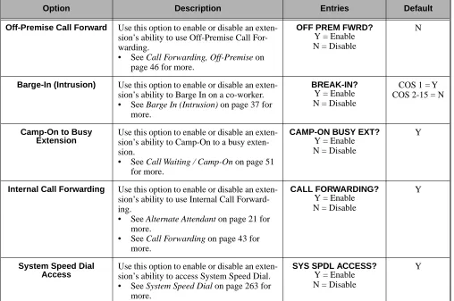
• In Program 0101 - Barge-In (Intrusion) (page 362), enter Y to enable Barge In in the extension’s Class of Service.
• In Program 0101 - Privacy (page 363), enter N to disable Privacy in the extension’s Class of Ser-vice.
• In Program 1801 - Extension Class of Service Assignment (page 450), assign Class of Service to extensions.
• In Program 0101 - Barge-In (Intrusion) (page 362), enter N to disable Barge In in the extension’s Class of Service.
• In Program 1801 - Extension Class of Service Assignment (page 450), assign Class of Service to extensions
If yes
Barge In (Intrusion)
Programming List
Program 0101 - Barge-In (Intrusion) (page 362)
In an extension’s Class of Service, enter Y to allow the extension to Barge In on another exten-sion.
Program 0101 - Privacy (page 363)
In an extension’s Class of Service, enter N to disable Privacy for the extension. Program 1801 - Extension Class of Service Assignment (page 450)
Assign Class of Service to extensions.
Other Related Features
Attendant Position (page 24)
Since the attendant is never busy, Intercom callers cannot Barge In on an attendant. Conference (page 79)
An extension user can Barge In on a Conference. Forced Trunk Disconnect (page 137)
As an alternative to Barging In, disconnect the trunk instead. Privacy (page 226)
Privacy blocks Barge In attempts.
Feature Operation
To Barge-In on a call:
1. Call busy extension. OR
Press line key for busy trunk. OR
Press ICM and dial 401 for busy trunk (i.e., using Direct Trunk Access). OR
Press ICM and dial #901 for busy trunk (i.e., using Line Dial-up). OR
Press ICM and dial Trunk Group access code (e.g., 9).
2. Dial 4.
3. Join the conversation in progress. Busy tone.
N/A
Battery Backup
Battery Backup
Description
In the event of commercial AC power failure, the battery on the CPU PCB provides short-term backup of system memory and the system time and date (Real Time Clock). This battery will hold memory and time and date for up to 10-14 days. When commercial AC power is restored, the sys-tem restarts with all programming and the time and date intact.
Additional Battery Backup capability can be provided by a customer-supplied Uninterruptable Power Supply (UPS). The length of the time the UPS will power the system when power fails depends on the capacity of the UPS unit. Consult with the UPS manufacturer for the specifics. When sizing a UPS unit, keep in mind that a fully-loaded 4-slot cabinet requires 165 VA. Refer to the Hardware Manual for additional details.
Conditions None
Default Setting None
Programming List
None
Other Related Features
When commercial AC power fails, the CPU battery does not back up the status of the following: ● Call Forwarding
● Call Waiting / Camp On
● Do Not Disturb
● Message Waiting
● Microphone Mute
● Trunk Queuing
System Programming Backup and Restore (page 287)
You can use PC Card P/N 85880 or P/N 80050-V**.** (with system software preloaded) to back up and restore your site data.
Time and Date (page 312)
The battery on the CPU PCB backs up the CPU Real Time Clock for 10-14 days.
Feature Operation
If properly installed, Battery Backup is automatic during AC power failures and brownouts. LCCPU 01.00.00 Available.
Call Coverage Keys
Call Coverage Keys
Description
A keyset can have Call Coverage Keys for a co-worker’s extensions, Ring Group master numbers and UCD group master numbers. The Call Coverage Key lights when the co-worker’s extension is busy, flashes slowly when the co-worker has an incoming call, and flashes fast when the co-worker is in Do Not Disturb. The Call Coverage Key can ring immediately when a call comes into the cov-ered extension, ring after a delay or not ring at all. In addition, the keyset user can press the Call Coverage Key to intercept their co-worker’s incoming call. They can also go off hook and press the Call Coverage key to call the covered extension. An extension can have as many Call Coverage Keys as they have available Programmable keys on their telephone.
Call Coverage Keys will intercept the following types of calls: ● Key Ring Calls
● Ringing Intercom calls
Conditions None
Default Setting
No Call Coverage Keys assigned. LCCPU 01.00.00 Available.
Call Coverage keys allow an extension user to cover a co-worker’s calls from their own telephone.
Call Coverage Key Busy Lamp Indications
When the key is: The covered extension is:
Off Idle or not installed
On Busy
Flashing slowly Ringing
Call Coverage Keys
Programming Guide
Programming List
Program 0403 - Call Coverage Delay (page 387)
For extensions with Delayed Ringing Call Coverage keys, set how long a call flashes the key at an extension before it starts to ring.
Step-by-step guide for setting up Call Coverage Keys
Step 1: Should the Call Coverage key have Immediate Ring, No Ring or Delayed Ring?
• For keysets, in Program 1701 - Call Coverage Immediate Ring (page 437), enter code 06 + the covered extension, Ring Group master number or UCD Group master number to assign an Immedi-ate Ring Call Coverage Key.
• For DSS Consoles, in Program 1704 - Call Cov-erage Immediate Ring (page 445), enter code 06 + the covered extension, Ring Group master num-ber or UCD Group master numnum-ber to assign an Immediate Ring Call Coverage Key.
• For keysets, in Program 1701 - Call Coverage No Ring (page 437), enter code 07 + the covered extension, Ring Group master number or UCD Group master number to assign a No Ring (lamp only) Call Coverage Key.
• For DSS Consoles, in Program 1704 - Call Cov-erage No Ring (page 445), enter code 07 + the covered extension, Ring Group master number or UCD Group master number to assign a No Ring (lamp only) Call Coverage Key.
• For keysets, in Program 1701 - Call Coverage Delay Ring (page 437), enter 08 + the covered extension, Ring Group master number or UCD Group master number to assign a Delay Ring Call Coverage Key.
• For DSS Consoles, in Program 1704 - Call Cov-erage Delay Ring (page 445), enter 08 + the cov-ered extension, Ring Group master number or UCD Group master number to assign a Delay Ring Call Coverage Key.
• In Program 0403 - Call Coverage Delay
(page 387), enter the interval after which a Delay Ring Call Coverage Key begins to ring.
Immediate Ring
No Ring
Call Coverage Keys
Program 1701 - Programmable Function Key Assignments (page 436)
Assign a programmable key on an extension as a Call Coverage Key (code 06 = immediate ring key, code 07 = no ring key, code 08 = delay ring key). The option is 300-331 (covered extension number).
Program 1704 - DSS Console Key Assignment (page 444)
Assign a programmable key on an extension as a Call Coverage Key (code 06 = immediate ring key, code 07 = no ring key, code 08 = delay ring key). The option is 300-331 (covered extension number).
Other Related Features
Direct Station Selection (DSS) Console (page 98) DSS Consoles can have Call Coverage keys. Hotline (page 160)
Hotline keys provide many of the features available with Call Coverage keys. Intercom (page 165)
A user can press a Call Coverage Key as an alternative to dialing Intercom numbers. Key Ring (page 170)
Call Coverage will pick up Key Ring calls. Transfer (page 324)
An extension user can Transfer a call to the covered extension by pressing the Call Co verage key. Voice Over (page 350)
After calling a co-worker by pressing their Call Coverage key, and extension user can dial 9 to leave a Voice Over (if enabled in programming).
Feature Operation
To answer a call ringing or flashing a Call Coverage Key:
1. Press flashing Call Coverage Key.
To place a call from an idle Call Coverage Key to the covered extension:
1. Press Call Coverage Key.
2. Speak with co-worker at the covered extension. (Optional) Ringing.
Slowly flashing Call Coverage Key.
Two beeps.
Call Forwarding
Call Forwarding
Description
Call Forwarding permits an extension user to redirect their call to another extension. The types of Call Forwarding are:
● Call Forwarding when Not Answered
Calls ringing the extension forward when not answered. ● Call Forwarding when Busy or Not Answered
Calls ringing the extension forward when not answered, and all calls forward while the exten-sion is busy.
● Call Forwarding Immediate
All calls to the extension forward immediately.
Extension user’s can chain Call Forwards. For example, extension 301 can forward all calls imme-diately to 304, which in turn can forward all calls immeimme-diately to extension 302. Any co-worker calling 301 or 304 goes to 302 instead. If extension 302 is Call Forwarded to Voice Mail, callers to 301 or 304 go directly to 302’s mailbox.
Conditions
A system reset or power failure cancels Call Forwarding.
Default Setting Enabled
Programming Guide
LCCPU 01.00.00 Available.
Call Forwarding ensures that the user’s calls are covered when they are away from their work area.
Step-by-step guide for setting up Call Forwarding
Step 1: Should an extension be able to forward their calls to a co-worker?
• In Program 0101 - Internal Call Forwarding (page 362), enter Y to enable Call Forwarding. • In Program 1801 - Extension Class of Service
Assignment (page 450), assign Class of Service to extensions.
• In Program 0101 - Internal Call Forwarding (page 362), enter N to disable Call Forwarding. • In Program 1801 - Extension Class of Service
Assignment (page 450), assign Class of Service to extensions.
If yes
Call Forwarding
Programming List
Program 0101 - Internal Call Forwarding (page 362)
In an extension’s Class of Service, enter Y to enable internal Call Forwarding. Program 0403 - Call Forward Ring No Answer (page 386)
For Call Forwarding Ring No Answer, set how long a forwarded call rings an unanswered extension before routing to the forwarding destination.
Program 1801 - Extension Class of Service Assignment (page 450) Assign Class of Service to extensions.
Other Related Features
Call Coverage Keys (page 40)
Call Forwarding will not reroute a call ringing a Call Coverage Key. Direct Inward Line (page 88)
Call Forwarding will reroute Direct Inward Lines. Do Not Disturb (page 114)
Call Forwarding considers an extension in DND as busy. In addition, an extension can have both DND and Call Forwarding enabled at the same time.
Extension Hunting (page 121)
If a member of a Circular or Terminal Hunting group forwards their calls, hunting will follow Call Forwarding. If a member of a UCD Hunting group forwards their calls, calls to the exten-sion follow forwarding but calls to the UCD master number do not.
Extended Ringing (page 119)
With Extended Ringing enabled, RNA call forwarding rings an extension for the Number of Extended Rings before routing the forwarded destination.
Group Ring (page 144)
Call Forwarding will not reroute Group Ring calls. Intercom (page 165)
Call Forwarding when Busy and Call Forwarding when Busy/Not Answered will not reroute voice-announced Intercom calls. It will reroute only ringing Intercom calls.
Key Ring (page 170)
Call Forwarding will not reroute Key Ring calls. Line Keys (page 176)
Call Forwarding will not reroute calls ringing line keys. Loop Keys (page 179)
Call Forwarding will not reroute a call ringing a loop key (unless the call is a DIL).
Step 2: When a user enables Ring No Answer forwarding, does an unanswered call ring the forwarding destination after the correct interval?
• In Program 0403 - Call Forward Ring No Answer (page 386), leave at the current setting.
• In Program 0403 - Call Forward Ring No Answer (page 386), change the entry to meet the site’s requirements.
Step-by-step guide for setting up Call Forwarding
If yes
Call Forwarding
Message Waiting (page 187)
● An extension user cannot leave a Message Waiting at an co-worker that has Call Forward-ing Immediate (*34) enabled. PressForward-ing MW automatically leaves a message at the for-warding destination instead.
● An extension user cannot leave a Message Waiting at a busy co-worker that has Call For-warding Busy/No Answer (*32) enabled. Pressing MW will automatically leave a mes-sage at the forwarding destination instead.
Selectable Display Messaging (page 256)
Enabling or canceling Call Forwarding cancels an extension’s Selectable Display Messaging. Transfer (page 324)
Call Forwarding will reroute transferred calls.
Feature Operation
To activate or cancel Call Forwarding:
1. Press ICM.
2. Dial *3.
3. Dial Call Forwarding type:
0 = Cancel your extension’s Call Forwarding 2 = Call Forwarding Busy/No Answer 4 = Call Forwarding Immediate 6 = Call Forwarding No Answer
7 = Personal Answering Machine Emulation (see Voice Mail on page 340 for more). 4. Dial destination extension (or 0 for your operator).
OR
Dial Voice Mail master number. OR
Press Voice Mail key.
5. Press SPK to hang up.
Once you forward, only the user at the forwarding destination can place an intercom call to you.
You can forward your phone to another destination without first canceling Call For-warding. For example, you can dial *34 + 0 to immediately forward to the operator, then later on dial *34 + 700 to immediately forward to Voice Mail.
Dial tone. ICM and SPK on.
Dial tone stops. ICM and SPK on.
Dial tone.
ICM, DND and SPK on.
Dial tone off.
Call Forwarding, Off-Premise
Call Forwarding, Off-Premise
Description
Call Forwarding Cancel
Call Forwarding Cancel
Description
Call Timer
Call Timer
Description
Call Timer lets a keyset user with a Call Timer key time their trunk calls on the telephone display. There are two types of Call Timer keys:
● Manual Call Timer
The Manual Call Timer key works like a stopwatch. Pressing the key turns on the timer, while pressing the key a second time resets and turns off the timer. With a Manual Call Timer key, the timer will not start automatically. For example, if an extension user presses the Manual Call Timer key and calls three clients, the display will show the total elapsed time for all three calls. The user can also press the Manual Call Timer key to time events anytime while their phone is idle.
● Automatic Call Timer
The Automatic Call Timer key will automatically start the Call Timer for each new trunk call, without the user having to press the key. The Automatic Call Timer can also work like a Man-ual Call Timer key: push to turn on, then push a second time to reset and turn off. There is no need to have a Manual and Automatic Call Timer key on the same phone.
Conditions None
Default Setting
No Call Timer keys assigned.
Programming Guide
LCCPU 01.00.00 Available.
Call Timer helps users that must keep track of their time on the phone.
Step-by-step guide for setting up Call Timer
Step 1: Should extension have a Manual Call Timer key?
• In Program 1701 - Call Timer Key (page 438), assign a Manual Call Timer key (code 16 + 1). Make sure you do not also have an Automatic Call Timer key assigned (code 16 + 2).
• In Program 1701 - Call Timer Key (page 438), make sure the extension does not have a Manual Call Timer key assigned (code 16 + 1).
If yes
Call Timer
Programming List
Program 1701 - Call Timer Key (page 438)
Assign a programmable key on an extension as a Call Timer key (code 16). The options are manual (1) and automatic (2).
Other Related Features
Hold (page 156)
A user’s Call Timer starts when they pick up a call from Hold. If they place the call on Hold and another user picks it up, the timer restarts for the new user.
Central Office Calls, Placing (page 63)
Call Timer shows the time a user has been on a trunk call. Station Message Detail Recording (page 277)
The SMDR report also keeps track of the time on a call.
Step 2: Should extension have an Automatic Call Timer key?
• In Program 1701 - Call Timer Key (page 438), assign an Automatic Call Timer key (code 16 + 2). Make sure you do not also have a Manual Call Timer key assigned (code 16 + 1).
• In Program 1701 - Call Timer Key (page 438), make sure the extension does not have an Auto-matic Call Timer key assigned (code 16 + 2).
Step-by-step guide for setting up Call Timer
If yes
Call Timer
Feature Operation
To time your trunk call if you have an Automatic Call Timer key:
1. Place or answer trunk call.
2. The Call Timer starts automatically.
You can press the Automatic Call Timer key once to turn the timer off. Press the key a second time to restart the timer.
You can also press CHECK + the timer key to restart the timer.
To time your call if you have a Manual Call Timer key:
You can also use your Manual Call timer key as a stop watch while your phone is idle. 1. Place or answer Intercom or trunk call.
2. Press Manual Call Timer key.
You can press the Manual Call Timer key once to turn the timer off. Press the key a sec-ond time to restart the timer.
You can also press CHECK + the timer key to restart the timer. Conversation with caller.
Automatic Call Timer key on. Timer in first line of display.
Call Waiting / Camp-On
Call Waiting / Camp-On
Description
With Call Waiting, an extension user may call a busy extension and wait in line (Camp-On) without hanging up. When the user Camps-On, the system signals the busy extension with two beeps indi-cating the first waiting call. The beeps periodically repeat while the call waits. The call goes through when the extension becomes free.
If an extension has more than one caller waiting, they queue on a first-in/first-out basis (FIFO). The extension will not hear Camp-On beeps for additional waiting calls.
Conditions
● A system reset or power failure cancels all Camp-Ons system wide.
● While busy on a call, Camp-On tones occur only for the first incoming call and do not repeat.
Default Setting
Call Waiting tones enabled.
Programming Guide
LCCPU 01.00.00 Available.
Call Waiting helps busy extension users know when they have additional waiting calls. It also lets callers wait in line for a busy extension without being forgotten.
Step-by-step guide for setting up Call Waiting / Camp-On
Step 1: Should extension be able to Camp On to a busy co-worker?
• In Program 0101 - Camp-On to Busy Extension (page 362), enter Y in each Class of Service that should allow users to Camp-On to a busy exten-sion.
• In Program 0101 - Privacy (page 363), be sure Privacy is disabled at the destination extension (N).
• In Program 0101 - Camp-On to Busy Extension (page 362), enter N in each Class of Service that should prevent users from Camping-on to a busy extension. Entering N automatically converts an extension’s Camp On to Callback.
If yes