IEEE TRANSACTIONS ON INDUSTRIAL ELECTRONICS, VOL. 42, NO. 2, APRIL 1995 139
Using a NeuralFuzzy System to Extract Heuristic
Knowledge of Incipient Faults in Induction
Motors: Part 11-Application
Paul
V. Goode, Student Member, IEEE, and MO-yuenChow,
Senior Member, IEEEAbstract-The use of electric motors in industry is extensive. These motors are exposed to a wide variety of environments and conditions which age the motor and make it subject to incipient faults. These incipient faults, if left undetected, contribute to the degradation and eventual failure of the motors. Part I of this paper introduced a hybrid neuraVfuzzy fault detector to perform fault detection tasks. Part I also discussed the purpose and methodology for combining the technologies of artificial neural networks and fuzzy logic for fault detection applications. This paper uses the hybrid neuraYfuzzy fault detector to solve the motor fault detection problem. As an illustration, the neuraVfuzzy fault detector will be used to monitor the condition of the motor bearing and the stator winding insulation. The initialization and training of this fault detector is in accordance with the procedures outlined in Part I of this paper. Once the neurdfuzzy fault detector is trained, the detector not only can provide accurate fault detector performance, but can also provide the heuristic
reasoning behind the fault detection process and the actual motor fault conditions. With better understanding of the heuristics through the use of fuzzy rules and fuzzy membership functions, we can have a better understanding of the fault detection process of the system, thus we can design better motor protection systems.
I. MOTOR BEARING WEAR FAULT DETECTION
USING THE NEuRAL/FUZZY SYSTEM
S MENTIONED in
Part I of this paper, the
two mostA
popular faults, bearing wear and insulation failure, are used here to illustrate how to use the proposed neurallfuzzy system for motor fault detection. The neurdfuzzy motor fault detector is first trained to learn the bearing wear faults. Bearing wear in a single-phase induction motor contributes to the overall power loss,PI,,,,
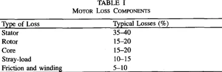
experienced by the motor. Table I[25] indicates the relative contribution of the different forms of power losses experienced by a typical four-pole motor. These losses sum together to create
Ploss.
The stator losses are the copper losses experienced by the windings in the stator. Rotor losses are caused by changes in motor slip. Core losses are a result of the hysteresis and eddy currents caused by the type of magnetic material used. Stray-load losses are a factor of several minor losses such as
flux leakage induced by the motor current, air gap, etc. The friction and winding losses are mechanical losses due to the friction caused by bearing wear and the windage losses caused by rotating elements of the motor.
Manuscript received March 5 , 1994; revised May 31, 1994. This work received the support of National Science Foundation Grant no. ECS-8922727.
The authors are with the Department of Electrical and Computer Engineer- ing, North Carolina State University, Raleigh, NC 27695 USA.
IEEE Log Number 9408820.
TABLE I
MOTOR LOSS COMPONENTS
Type of Loss
Stator 3 5 4 0
Typical Losses (%)
Rotor 15-20
Core 15-20
Stray-load 1G15
Friction and winding 5-10
Bearing wear, as indicated in Table I, comprises five to ten percent of the overall losses experienced by a healthy motor. It is a common practice [ 111, [32] to group the stray- load losses with the friction and winding losses into one loss parameter,
Protational
loss, because it is difficult to determine these losses individually. The “best guess” of the fuzzy rules is made by looking at the conceptual surface plot of Fig. 1 and heuristically determining the ranges of low, medium, and high and noting the bearing condition in these ranges. Using this principle, along with the percentage information from Table I, general rules for bearing wear classification can be constructed as follows:IF
Protational lossI
0 . 2 0 ( 8 o s s ) THEN GOODIF
0 . 2 5 ( 8 o s s )<
Protational loss THEN BAD.(1)
Training data for bearing wear was obtained using these same heuristics.
The neurdfuzzy bearing fault detector is trained in accor- dance with the procedure outlined in
Part I, Section 111. The
first step of the training requires initialization of the fuzzy membership function module. For this problem, the fuzzy membership function module consists of two independent subnetworks, one for motor current and one for rotor speed. Each subnetwork is initialized with the generalized heuristics of low, medium, and high as shown inPart I, Fig.
3. This initialization gives the module a better starting point for classification. The “best guess” of the fuzzy rules is made from whatever minimal heuristic knowledge is available. r f no minimal heuristic knowledge is available, a simple guess is made. This initial rule base (best guess) is shown in Table 11,where B, represents the bearing condition.
The neurdfuzzy bearing fault detector was trained while not allowing the weights of the rule module to change. The
02784046/95$04.00 0 1995 IEEE
I ,
-
140 IEEE TRANSACTIONS ON INDUSTRIAL ELECTRONICS, VOL. 42, NO. 2, APRIL 1995
1 1
- -
+--
itcration=O +-
iteraticin=150-
iteration=900- -
-iteration=50.. . _ ’ +
0.8
0.6
P I 0.4
0.2
0
0 0.2 0.4 0.6 0.8 1
Normalized Current
1
0.8
0.6
hl
0.4
0.2
0
Fig. 1.
2 weights constant.
Bearing wear membership functions after training with initial module
0.8
0.6
Pm 0.4
0.2
0
0 0.2 0.4 0.6 0.8 1
Normalized Speed
Fig. 2. Medium membership function for speed at different iterations.
As stated in
Part I of this paper, these types of violations
are generally quite obvious. The violation made by the speed medium membership function is its apparent splitting into two different membership functions. This can be verified by observing the medium membership function at different iterations during training. Fig. 2 displays a “snapshot” of the membership functions for medium speed at different stages of the training.Notice how the shape of the medium speed membership function seems to be still changing at a very slow rate when the training criterion is finally met. This membership function is in the process of splitting into two independent distributions, one of which would be a subset of the low membership function shown in Fig. 1. This is heuristically unacceptable. Furthermore, interpreting the resulting membership function, TABLE II
INITIAL Fuzzy RULES FOR BEARING WEAR indicates that while a speed of N 0.1 (pu) and
-
0.7 (pu) have a grade of membership of N 0.5, speeds between these twoIf I is: values have a lower grade of membership. In effect, a speed
of 0.1 (pu) is more medium than a speed of 0.5 (pu). This,
low low good
low medium fair
too, is heuristically unacceptable. As a result, the initial rule
low high good
medium low fair base is suspected of having an incorrect rule (or rules). It is
medium medium fair these incorrect rules (which are not allowed to change at this
medium high fair point) that are forcing the membership functions to change in
high
The network is trained again while allowing the weights
high medium fair
high high good
of the rule module to change. After the training criterion was
and w is: Then B, is:
low bad this heuristically unacceptable fashion.
reached (and 100% classification), the weights were analyzed to determine if any incorrect rules were present in the initial rule base. The weight analysis is shown below in Table 111. The “Antecedent” column represents each antecedent node by an abbreviation. The abbreviation corresponds to a combination of the current and inputs, respectively. For example,
G‘LL” represents the antecedent node.
The other three columns represent the three consequent nodes
weights from the antecedent node to the consequent node. If the cell is marked with a
d ,
then the weight changed correctly. For example, the rule base indicates that the an- tecedent of low current, high speed should have an output of good. Therefore, the weight connecting to the good node from the antecedent node of “LH’ should increase positively in value. Because there is a,/
in the cell, the weight did membership functions were extracted using the procedureoutlined in
Part I, Section 111, i.e., by evaluating the output
nodes of the membership function module. The resulting membership functions are shown in Fig. 1. These membership functions indicate the actual regions of low, medium, and high for classification with the initial rule base. For example, to= low, the range Of high current whereas the range Of low covers roughly the bottom
half of the input range of motor speed.
Although the resulting neurdfuzzy system classified 100% of the training data (while only 93% of the testing data), it can be Seen from Fig. 1 that the medium membership function for the speed violates our heuristic reasoning for what is considered to be a fuzzy logic membership function.
= high and
GOODE AND CHOW USING A NEURAL/FuZZY SYSTEM TO EXTRACT HEURISTIC KNOWLEDGE OF INCIPIENT FAULTS IN INDUCTION MOTORS 141
TABLE III
CHANGE IN ~ I AFuzzy L RULE^ FOR BEARING WEAR
Antecedent Good Fair Bad
LL -2.4
J
+4.0LM +0.6
J
J
J
J
-1.1
J
LH
d
ML
J
MM +0.9
J
J
MH +5.9 -0.3
J
J
J
HL
J
J
J
+5.5HM
J
-0.1 +1.5HH
increase positively in value. Likewise, the other two weights for the “LH’ node should decrease negatively in value because the rule base indicates that they are not the antecedents for this case of low current, high speed. Because there is a J in the cell, the weights did decrease negatively in value.
If the cell contains a negative value, then it indicates a rule that is decreasing in strength. For example, the rule base indicates that the antecedent of medium current, high speed should have an output of fair. However, the weight connecting this antecedent to thefair consequence node decreased in value by 0.3. This decrease indicates a weakening of the rule “if the current is medium and the speed is high, then the bearing condition is fair.” Likewise, if a cell contains a positive value, then it indicates a consequent attempting to become a rule. For example, the positive increase in the weight connecting the antecedent of medium current, high speed to the good consequence node increased in value by 5.9. This increase indicates a consequence that was not a rule increasing in strength to attempt becoming a rule.
Although Table 111 reflects several cases of rule weights changing in the incorrect direction, two cases demand im- mediate attention. These are case 1, low current, low speed and case 2, medium current, high speed. Both of these cases exhibit large changes in amplitude and a change in more than one weight. Because one of these weights in each case is a rule weight (correct consequent by rule base initialization), the change indicates that the rule is trying to change from one consequent to another.
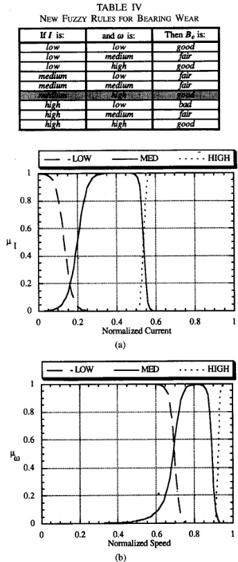
Of these two candidates for an incorrect rule, case 2 will be addressed first. This case is chosen over case 1 because case 1 does not have training data in its region. Case 2 does have training data in its region, thus making case 2 a more important candidate. Therefore, the rule base is modified to reflect the attempted change through training. This attempted change increased the weight connecting to the good consequence while decreasing the weight connecting to the fair consequence. Therefore, the rule for medium current, high speed is changed from having a consequence of fair to having a consequence of good. The new rule base is reflected in Table IV. The rule that changed is shaded.
The neuravfuzzy system is trained while holding this new rule base constant. As mentioned previously, this training is done to determine if any other fuzzy rules are candidates for being incorrect rules. The resulting membership functions are shown in Fig. 3. The rule base is considered not to have any
TABLE N
NEW FUZZY RULES FOR BEARING WEAR
P I
0 0.2 0.4 0.6 0.8 1
Normalized Current
(a)
1
0.8
0.6
r:
0.4
0.2
0
0 0.2 0.4 0.6 0.8 1 Normalid Speed
(b)
Fig. 3.
2 weights constant.
incorrect rules because these membership functions are in line with our heuristic reasoning of what the membership functions should look like. Furthermore, this network also classified 100% on the training data and the 98% on the testing data.
Now that the incorrect rule analysis has been done, the new rule base is examined for unnecessary rules by once again reinitializing the neuraVfuzzy system and allowing the weights of the rule module to change. The rule weights of this module are examined for unnecessary rules after the neuravfuzzy fault detector reaches the training criterion. One hundred percent classification of both the training and testing data were obtained.
An antecedent-consequent rule is a candidate for an unnec- essary rule if its weight changes sign, as mentioned in Part I, Section 111. Table V reflects the weights which changed sign by a shaded
X.
The weights marked with a J did not change sign and are not candidates for unnecessary rule nodes.142 IEEE TRANSACTIONS ON INDUSTRIAL ELECTRONICS, VOL. 42, NO. 2, AF'W 1995
1
-
-Low-
=
. - - .
--
HIGHI
1
0.8
0.6
P I 0.4
0.2
0
0 0.2 0.4 0.6 0.8 1 Normalized Current
(a)
HIGH
I
1
0.8
0.6
P I 0.4
0.2
0
0 0.2 0.4 0.6 0.8 1
Normalized Current
(C)
I-
-Low -MED . - . . - H I G H0.8
0.6
Pm
0.4
0.2
0
0 0.2 0.4 0.6 0.8 1
Normalized Speed
(b)
I 0.8
0.6
c:
0.4
0.2
0
0 0.2 0.4 0.6 0.8 1
Normalized Speed
( 4
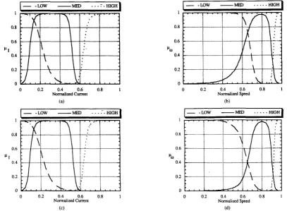
Fig. 4. (Top) Bearing wear membership functions after training with new module 2 weights changing. (a) With respect to current. (b) With respect to speed. (Bottom) Bearing wear membership functions after training with reduced module 2 weights changing. (c) With respect to current. (d) With respect to speed.
TABLE VI TABLE V
CHANGE IN SIGN OF NEW FUZZY RULES FOR BEARING WEAR REDUCED FUZZY RULES FOR BEARING WEAR
If I is: and w is: Then B, is:
low medium fair
low high good
medium low fair
medium medium fair
medium high good
high low bad
TABLE VII
REDUCED FUZZY RULE BASE WEIGHTS BEFORE AND TRAINING
The three shaded weights indicated by an
X
changed sign, thus causing those antecedents to have two consequences. Because this is impossible, these antecedent-consequence rules are candidates for unnecessary rules and are therefore elimi- nated from module 2. Module 2 now has only six antecedent nodes. The new rule base reflects this in Table VI.This action can be verified in two ways. The first verification is done by analyzing the rule weights of the rule module after training the neurdfuzzy system with the reduced rule base. If all the weights change appropriately (increase in absolute value), then the rule base is considered reduced and correct. This, in fact, was found to be true as shown in Table VII.
The second verification is done by comparing the resulting membership functions of module 1 trained with the rule base
,I
143 GOODE AND CHOW USING A NEURAWFUZZY SYSTEM TO EXTRACT HEURISTIC KNOWLEDGE OF INCIPIENT FAULTS IN INDUCTION MOTORS
: x 0 " ' I " ' I " ' I . ' ' " 5 2 ' '
0 0.2 0.4 0.6 0.8 1
Normalized Current
Fig. 5. Distribution of bearing wear fault data.
These results make heuristic sense if they are compared to the actual training data used (shown below). Referring to Fig. 5, it can be observed that the bearing condition is more dependent on motor speed than motor current, but is still a function of both inputs. Also note the absence of data from the low-current, low-speed and high-current, high-speed regions. As bearing wear increases, the rotor speed is reduced. This reduction in rotor speed causes an increase in slip, thus increasing motor current. Therefore, it is physically impossible for the motor to maintain a low current while decreasing rotor speed. This condition nullifies the possibility of data belonging to a low-current, low-speed region. Furthermore, the motor cannot maintain a high speed with increased bearing wear. As mentioned, the rotor speed will decrease and the motor current will increase. This condition excludes the possibility of data belonging to a high-current, high-speed region. This data verifies the resulting rules and membership functions obtained through training.
The training curves of the neurallfuzzy system for the determination of incorrect rules and unnecessary rules are shown in Fig. 6(a) and (b). Even though all of the cases reached the training criterion at different iterations, all training was executed until the maximum training time of all cases was reached (870 iterations). This was done for comparison purposes.
Fig. 6(a) illustrates the root-mean-square (rms) error curves for the determination of incorrect rules. The curves show that training with the incorrect rule base constant achieves a higher rms error than does training with the correct rule base constant. Both of these cases have almost reached their minimum error by the end of the training cycle. This is evident by the flattening of the error curve.
Fig. 6(b) illustrates the rms error curves for the determi- nation of unnecessary rules. The curves show that training with the reduced rule base has an rms error slightly higher than that of the correct rule base with the unnecessary rule nodes present. However, these two error curves do converge to the same low value of 0.0064 after 5000 iterations. The system with the unnecessary rule nodes can maintain a lower rms error than the system without the unnecessary rule nodes (until 5000 iterations have been reached) because it still uses
0.25
0.2
8
0.15B
0.10.05
n
-
-
Incorrect Rules-
C o q t Rules0 100 200 300 400 500 600 700 800
Number of iterations (a)
-New Rule Base
- -
-
-
Standard ANN-
-Reduced Rule Base0.25
0.2
0.15
8
0.1
0.05
0
o 100 200 300 400 500 600 700 800
Number of iterations (b)
Fig. 6.
essary rules.
(a) Determination of incorrect rules and (b) determination of unnec-
the unnecessary rule nodes that are present (remember, the rules during this phase are changing).
Fig. 6(b) also draws a comparison to a standard feedforward ANN with two inputs, eight hidden nodes, and three outputs. The neurallfuzzy systems are shown to have an initial error much less than the standard ANN. This is because it has a better starting point: the correct rule base and general membership functions. In the end, however, the two are proven to be almost equal in performance with the standard ANN obtaining an rms error of 0.0091 after 5000 iterations. The ANN also classifies 100% of the training and testing data.
11. MOTOR WSULATION WEAR FAULT
DETECTION USING THE NEURALFUZZY SYSTEM
The neurallfuzzy motor fault detector is also trained to learn insulation failure. The insulation condition was classified into three categories: good, fair, and bud. These classifications were made based upon life expectancy of the insulation as the stator winding temperature increases. This relationship is expressed by the Arrhenius equation shown below.
fife = AeG
,
( 2 )144
0 " ' I " ' I " ' I " ' I ' K .
0 0.2 0.4 0.6 0.8 1
Normalized C m n t Fig. 7. Distribution of insulation wear fault data.
obtain the constants A and B, the interested reader should refer to [20]. Using ( 2 ) , data classification for insulation failure was constructed based upon the following heuristics:
IF Life
2
10 weeks THEN GOODIF 10 weeks
>
Life 2 2 weeks THEN FAIR ( 3 )IF 2 weeks
>
Life THEN BAD.Training data was obtained using (2) and (3). The actual training data is shown in Fig. 7.
Note that the insulation condition is heavily dependent on motor current. This dependence is due to the Arrhe- nius life relation. The insulation condition is determined by the expected life given by the Arrhenius relation, which is dependent on the temperature of the stator windings. The temperature of the windings is a direct result of the operating environment and the current going through the windings. Because this work assumes an average operating environment (room temperature), the motor current becomes the major contributing factor. The neurdfuzzy motor fault detector will be used to verify that rotor speed is not a necessary input.
The neurdfuzzy insulation fault detector is also trained in accordance with the procedure outlined in
Part I, Section
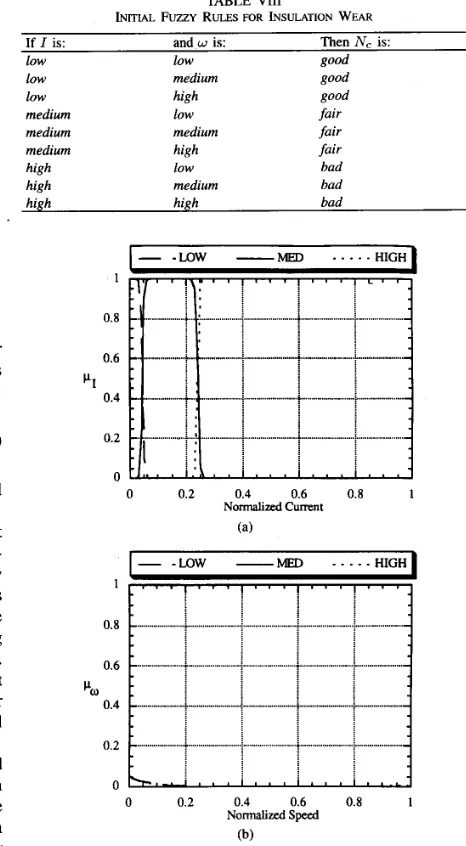
111. The first step of the training requires initialization of the fuzzy membership function module, which was initialized in the same manner as was done for the motor bearing wear problem. The "best guess" of the fuzzy rules for the insulation wear is made from the general knowledge of insulation wear dependence on current. If a best guess rule base was made based upon the conceptual plot of Part I, Fig. 1, then some of the rules would be incorrect and the training procedure would determine these. To avoid presenting this procedure twice, this best guess rule base is chosen to illustrate the ability of the neuravfuzzy motor fault detector to identify unnecessary inputs. This initial rule base is shown in Table VIII, whereN,
represents the winding insulation condition.The neural/fuzzy insulation fault detector was trained while not allowing the weights of the rule module to change. The membership functions were extracted using the procedure outlined in the Part I, Section 111, i.e., by evaluating the output nodes of the membership function module. The resulting membership functions are shown in Fig. 8. As before, these membership functions indicate the actual regions of low,
IEEE TRANSACTIONS ON INDUSTRIAL ELECTRONICS, VOL. 42, NO. 2, APRIL 1995
TABLE VI11
INITIAL FUZZY RULES FOR INSULATION WEAR
If I is: and w is: Then N , is:
low low good
low medium good
low high good
medium low fair
medium medium fair
medium high fair
high low bad
high medium bad
high high bad
1
0.8
0.6
1 1 0.4
0.2
0
1
0.8
0.6
%I
0.4
0.2
0
0 0.2 0.4 0.6 0.8 1
Normalized Current (a)
0 0.2 0.4 0.6 0.8 1
Normalized Speed
(b)
Fig. 8. Insulation wear membership functions after training with initial module 2 weights constant.
medium, and high for each of the respective regions necessary for classification with the initial rule base.
Fig. 8 indicates that the initial "best guess" of the rule base in Table VI11 was correct. Comparing the membership functions to the distribution of data in Fig. 7, it appears that the proper shapes of membership functions for the current have been found. Furthermore, the membership functions for the speed did go to zero. This would be heuristically expected because, according to Table VIII, the speed has no effect on the classification of the insulation condition. Because the speed membership functions are zero, that input is effectively cut out of the system. Thus, the system has become a one-input system that classifies with 100% accuracy on both the training and the testing data. As a result, no further training is necessary and
GOODE AND CHOW USING A NEURAUFUZZY SYSTEM TO EXTRACT HEURISTIC KNOWLEDGE OF INCIPIENT FAULTS IN INDUCTION MOTORS 145
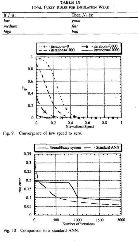
TABLE IX
FINAL FUZZY RLJLFS FOR INSULATION WEAR
If I is:
low good
medium fair
high bad
Then N , is:
I
- -
+..
iterationso 4-
itera1ionG3WI
-
-
-itcrations=lW -ituations=looOO0.8
0.6
’”0
0.4
0.2
0
I
-
. :
..”
...
j ... ”..
I....J
...”... 7I....
+. -...I
0 0.2 0.4 0.6 0.8 1 Normalized Speed
Fig. 9. Convergence of low speed to zero.
-
Neuravfuuy system-
-
Standard ANN1500 2000
0 500 ‘F
Number of iterations
Fig. 10 Comparison to a standard ANN.
the membership functions of Fig. 8 are assumed to be correct. The rules of Table VI11 now become those shown in Table IX.
The modifications to the speed membership functions can be seen in Fig. 9. This figure represents “snapshots” of the low-speed membership function taken at different times during training. The medium and high membership functions also converge to zero as shown previously in Fig. 8.
The performance of the neural/fuzzy fault detector for the insulation problem can also be compared to a standard feedforward ANN with two inputs, eight hidden nodes, and three outputs. The results are shown in Fig. 10. It can be seen that the neurallfuzzy system has a better starting point than the ANN. Although the ANN learns faster than the neurallfuzzy system, the two are almost equal after 2000 iterations of training. The ANN also classified 100% of the training and testing data.
111. CONCLUSION
A neurdfuzzy system has been proposed in this paper to perform bearing and insulation wear fault detection in single
phase induction motors. The neurallfuzzy system can provide quantitative descriptions of the motor faults under different operating conditions as well as qualitative heuristic explana- tions of these operating conditions and the fault detection procedures through fuzzy rules and membership functions. The resulting fuzzy rules and membership functions not only provided heuristic description of the fault detection process, but also the neurallfuzzy motor fault detector achieved 100% classification accuracy in both fault detection applications. This heuristic knowledge is gained through the use of a noninvasive fault monitoring scheme that requires essentially no expert knowledge of the motor to be monitored; however, a minimal amount of knowledge about the motor is required, as discussed in this paper. This knowledge provides more engineering insight into motor fault detection and the fault detection process, thus we can better understand the fault detection process and design better protection systems.
REFERENCES
[1] D. R. Boothman, E. C. Elgar, R. H. Rehder, and R. J. Woodall, “Thermal tracking-A rational approach to motor protection,” IEEE Trans. Power App. and Syst., pp. 1335-1344, Sept./Oct. 1974.
[2] S. Cambrias and S . A. Rittenhouse, “Generic guidelines for life exten- sion of plant electrical equipment,” Electric Power Research Institute Rep. EL-5885, July 1988.
[3] M. Chow, “Artificial neural network methodology in real-time incipient fault detection of rotating machines,” in Proc. Nut. Sci. Foundation Workshop on Artijcial Neural Network Methodology in Power Syst. Eng., Clemson University, Clemson, SC, 1990, pp. 8C85, Apr. 8-10,
[4] M. Chow and S. 0. Yee, “Application of neural networks to incipient fault detection in induction motors,” J. Neural Network Computing, Auerback, vol. 2, no. 3, pp. 26-32, 1991.
[SI -, “Methodology for on-line incipient fault detection in single- phase squirrel-cage induction motors using artificial neural networks,” IEEE Trans. Energy Conversion, vol. 6, no. 3, pp. 536545, Sept. 1991. [6] M. Chow, M. Peter Mangum, and S. 0. Yee, “A neural network approach to real-time condition monitoring of induction motors,” IEEE Trans. Ind. Electron., vol. 38, no. 6, pp. 448453, Dec. 1991.
[7] M. Chow, R. N. Sharpe, and J. C. Hung, “On the application and design of artificial neural networks for motor fault detection,” IEEE Trans. Ind. Electron., vol. 40, no. 3, pp. 181-196, Aug. 1991.
[8] M. Chow and P. Goode, “Adaptation of a neurdfuzzy fault detection system,” in Proc. IEEE Confi Decision and Contr., 1993.
[9] G. Cybenko, “Approximations by superpositions of a sigmoidal func- tion,” Mathematics of Control, Signals, and Syst., vol. 2, pp. 303-314, 1989.
[lo] P. Goode and M. Chow, “NeuraUfuzzy systems for fault detection in induction motors,” in Proc. IECON ’93, Honolulu, HI, Nov. 1993. [l 11 B. S . Gum and H. R. Hiziroglu, Electric Machinery and Transformers.
San Diego, CA: Harcourt Brace Jovanovich, 1988.
[I21 K. Homik, M. Stinchcombe, and H. White, “Multi-layer feedforward networks and universal approximators,” Neural Networks, vol. 2, pp. 359-366, 1989.
[13] J. C. Hung and B. J. Doran, “High reliability strapdown platforms using two-degree-of-freedom Gyros,” IEEE Trans. Aerospace and Electron. Syst., vol. 9, no. 2, pp. 253-259, March 1973.
[14] R. Isermann and B. Freyermuth, “Process fault diagnosis based on process model knowledge-Part I: Principles for fault diagnosis with parameter estimation,” Trans. ASME, vol. 113, pp. 620-626, Dec. 1991. [15] A. Keyhani and S. M. Miri, “Observers for tracking of synchronous machine parameters and detection of incipient faults,” IEEE Trans. Energy Conversion, vol. 1, no. 2, June 1986.
[16] G. J. Klir and T. A. Folger, Fuuy Sets, Uncertainty, and Information. Englewood Cliffs, NJ, Prentice-Hall, 1988.
[17] B. Kosko, Neural Networks and Fuuy Systems: A Dynamical Systems Approach to Machine Intelligence. Englewood Cliffs, NJ: Prentice- Hall, 1992.
146 IEEE TRANSACTIONS ON INDUSTRIAL ELECTRONICS, VOL. 42, NO. 2, APRIL 1995
[19] D. Morel and P. Neau, “Vibration monitoring of heavy duty machines,”
[20] W. Nelson, Accelerated Testing.
[21] H. Okada, N. Watanabe, A. Kawamura, and K. Asakawa, “Initializing multilayer neural networks with fuzzy logic,” in Proc. Int. Joint Con$ on Neural Networks, vol. 1, pp. 239-244, 1992.
[22] D. E. Rumelhart, G. E. Hinton, and R. J. Williams, ‘‘Learning intemal representations by error propagation,” Parallel Distributed Processing: Explorations in the Microstructure of Cognition. Vol. I : Foundations, D. E. Rumelhart, J. L. McClelland and the PDP research group, Eds. Cambridge, M A MIT, pp. 318-362, 1986.
[23] D. E. Schump, “Reliability testing of electric motors,” IEEE Trans. Ind. Applicar., vol. 25, no. 3, pp. 386390, May/June 1989.
[24] R. N. Sharpe and M. Chow, “A methodology using fuzzy logic to optimize feedforward artificial neural network configurations,” IEEE Trans. Syst., Man, and Cybern., vol. 24, no. 5, 1994.
[25] R. W. Smeaton, Motor Application and Maintenance Handbook, 2nd ed. New York: McGraw-Hill, 1987.
[26] A. K. Sood, A. F. Ali, and N. A. Henein, “Engine fault analysis Part
I: Statistical methods,” IEEE Trans. Ind. Electron., vol. 32, no. 4, Nov. 1985.
[27] P. J. Tavner and P. James, Condition Monitoring of Electrical Machines. New York Research Studies Press Ltd., Wiley.
in IEEE Trans. Comput., vol. 40, no. 12, pp. 1320-1336, Dec. 1991. New York Wiley, 1990.
[28] P. J. Tavner, “Condition monitoring, the way ahead for large electrical machines,” Fourth Int. Con5 on Electric Machines and Drives, pp. 159-162, Sept. 13-15, 1989.
[29] A. E. Taylor and W. R. Mann, Advanced Calculus. New York Wiley, 1983.
[30] J. E. Timperly, “Incipient fault detection through neutral RF monitoring of large rotating machines,” IEEE Trans. Power App. and Syst., vol. 102, no. 3, March 1983.
[31] L. A. Zadeh, “Fuzzy sets,” Inform. and Contr., vol. 8, pp. 338-353, 1965.
[32] D. Zorbas, Elecrrical Machines. St. Paul, MN: West, 1989.
Paul V. Goode (S’92), for a photograph and biography, please see page 138 of this issue of this TRANSACTIONS.