An Enhanced High Performance and Low Power FIR Low Pass Filter
Based on Array Multiplier
Pavan Mankal
Department of Electronics & Telecommunication Engineering
Guru Nanak Dev Engineering College, Bidar, Karnataka India
Abstract— Finite impulse response (FIR) filters are importantbuilding blocks for various digital signal processing (DSP) applications. Recently, because of the increasing demand for video-signal processing and transmission, high speed and high-order FIR filters have frequently been used to perform adaptive pulse shaping and signal equalization on the received data in real-time. Multiplication is a very important operation in many DSP applications. FIR filters are basic building blocks for various DSP applications. FIR contains 3 blocks adder, multiplier and delay elements. To achieve a high performance in the filter the thing is to concentrate on the type of adders, multipliers used in the FIR circuit. We performed it in different CMOS technology like 45, 90,180nm, and require 40.38% less area than the original FIR filter. Design is coded in Verilog HDL maintaining industry standard coding guidelines. Verification plan is developed describing simulation of design and synthesis strategy documented. Synthesis scripts were coded, design is synthesized on 45,90,180nm technology and timing checks performed. The details of synthesis is mentioned in the paper.
Keywords: FIR, DSP, CMOS Technology, HDL
I. INTRODUCTION
Finite impulse response (FIR) filters are important building blocks for various digital signal processing (DSP) applications. Recently, because of the increasing demand for video-signal processing and transmission, high speed and high-order FIR filters have frequently been used to perform adaptive pulse shaping and signal equalization on the received data in real-time. Signal processing algorithms often require a substantial amount of floating-point (or fixed-point) computations to be performed at real-time or near real-time speeds. A FIR filter is composed of multipliers and adders, and their performance adders determines the speed of FIR filter. An array multiplier is a digital combinational circuit that is used for the multiplication of two binary numbers by employing an array of full adders and half adders. This array is used for the nearly simultaneous addition of the various product terms involved. To form the various product terms, an array of AND gates is used before the adder array.
II. PROBLEM STATEMENT
Multiplication is a very important operation in many DSP applications. FIR filters are basic building blocks for various DSP applications. FIR contains 3 blocks adder, multiplier and delay elements. To achieve a high performance in the filter the thing is to concentrate on the type of adders, multipliers used in the FIR circuit. In traditional FIR Filters were implemented by a conventional number system their Speed was limited because of the multiply-accumulate operations since multiplier increases the complexity in the design. Later there were realize a fast FIR filter by utilizing
the Logarithmic Number System, which allows a simple implementation of multiplication using a fixed-point adder. In which multiply operation converts to an addition operation. And the serious demerit of Logarithmic Number System’s algorithm, conversions to and from the conventional number representations. And it also increases the hardware complexity. Therefore, a new method has to be devised, which can reduce the hardware complexity of the design and also increases the speed of the filter. This FIR filter design is implemented based on array multiplier. In our proposed system, the performance of FIR filter based on array multiplier compared with the LNS result. The comparison is based on cadence synthesis.
III. FILTERS
A circuit designed to perform the frequency selection is called a filter circuit. Filter is an AC circuit that separates some frequencies from others within mixed-frequency signals. Audio equalizers and crossover networks are two well-known applications of filter circuits.
A. Classification of Filters: 1) Passive Filters
Passive implementation of linear filters is based on the combination of resistors (R), inductors (L) and capacitors (C). These types are collectively known as passive filters, because they do not depend upon an external power supply and/or they do not contain active components such as transistors. Inductors block high-frequency signals and conduct low-frequency signals, while capacitors do the reverse. A filter in which the signal passes through an inductor, or in which a capacitor provides a path to ground, presents less attenuation to low-frequency signals than high-frequency signals and is a low-pass filter. If the signal passes through a capacitor, or has a path to ground through an inductor, then the filter presents less attenuation to high-frequency signals than low-frequency signals and is a high-pass filter. Resistors on their own have no frequency-selective properties, but are added to inductors and capacitors to determine the time-constants of the circuit, and therefore the frequencies to which it responds.
2) Active Filters
Fig. 3.1: A general finite impulse response filter with n stages, each with an independent delay, di and amplification
gain, ai.
3) Digital Filters
A digital filter is a system that performs mathematical operations on a sampled, discrete- time signal to reduce or enhance certain aspects of that signal. This is in contrast to the other major type of electronic filter, the analog filter, which is an electronic circuit operating on continuous-time analog signals. An analog signal may be processed by a digital filter by first being digitized and represented as a sequence of numbers, then manipulated mathematically, and then reconstructed as a new analog signal in an analog filter; the input signal is "directly" manipulated by the circuit.
B. Types of Digital Filter:
1) Infinite Impulse Response Filters
Infinite impulse response, or IIR, filters are the digital counterpart to analog filters. Such a filter contains internal state, and the output and the next internal state are determined by a linear combination of the previous inputs and outputs (in other words, they use feedback, which FIR filters normally do not). In theory, the impulse response of such a filter never dies out completely, hence the name IIR, though in practice, this is not true given the finite resolution of computer arithmetic. IIR filters normally require
2) Finite Impulse Response Filters
A filter implemented in a computer programs a discrete- concepts defines the behavior of such systems. Although a digital filter can be an IIR filter if the algorithm implementing it includes feedback, it is also possible to easily implement a filter whose impulse truly goes to zero after N time steps this is called a FIR filter.
C. Conventional Fir Filter Structure
[image:2.595.310.542.67.245.2]The conventional filter architecture is shown in Fig 3.2. In this implementation of the architecture using Logarithmic Number System, FP-to-LNS and LNS-to-FP conversions’ delays are effectively overcome by hiding them in the pipeline stages. Therefore, only the delay in an adder determines the pipeline clock frequency. The conversions may introduce latency by two clocks but will not cause significant performance degradation. Four kinds of specially-designed adders are marked with 1, 2, 3, and 4 in Figure3.2.
Fig. 3.2: Conventional FIR filter architecture
D. Proposed Fir Low Pass Filter
Goal: Implementation of FIR Low Pass filter based on array multiplier, to achieve higher speed.
The digital signal processing is used in a wide variety of real-time applications and is playing an important role in the digital revolution. FIR digital filters are the most fundamental DSP components. FIR filters have the advantage of stability and easy implementation. The design of FIR filters which aims at reducing the delay and increase the speed.
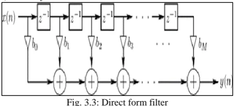
FIR filters are important building blocks for various DSP applications. Recently, because of the increasing demand for video signal processing and transmission, high-speed and high-order FIR filters have frequently been used to perform adaptive pulse shaping and signal equalization on the received data in real-time, e.g., ghost cancellation source coding, equalizer, Partial-Response Maximum Likelihood (PRML), and channel equalization. Signal processing algorithms often require a substantial amount of floating- point (or fixed-point) computations to be performed at real-time or near real-time speeds. Hence, an efficient VLSI architecture for a high-speed FIR filter is crucial. A FIR filter is composed of multipliers and adders, and their performance adders determines the speed of FIR filter. 1) Direct form FIR Filter
Fig. 3.3: Direct form filter
This scheme is generally considered to be the lowest area implementation; however, it suffers from speed disadvantage. The critical path consists of the CLK-to-Q delay and setup time of the storage register and one multiplication and addition stage, where is the number of filter taps.
E. Proposed FIR Filter Design Architecture
[image:2.595.307.550.542.652.2]way to reduce the power consumption of digital circuits is to reduce the supply voltage, since the average power consumption of CMOS digital circuits is proportional to the square of the supply voltage. The resulting performance loss can be overcome for standard CMOS technologies by introducing more parallelism and to modify the process and optimize it for low supply voltage operation
[image:3.595.306.543.72.731.2]Figure shows the basic block diagram for an FIR filter of length N. The delays result in operating on prior input samples. The hk values are the coefficients used for multiplication, so that the output at time n is the summation of all the delayed samples multiplied by the appropriate coefficients.
Fig. 3.4: Tap FIR Filter design
From the design of 8–tap low pass FIR filter design, the major elements required are
Delay element Multiplier Adder
In our implementation there are 8-filter taps that mean 8 filter coefficients with N=8. Filter coefficients are from h0 to h7 as shown above.
IV. IMPLEMENTATION USING THE MATLAB
MATLAB stands for "Matrix Laboratory" and is a numerical computing environment and fourth-generation programming language. Developed by The Math Works, MATLAB allows matrix manipulations, plotting of functions and data, implementation of algorithms, creation of user interfaces, and interfacing with programs written in other languages, including C, C++, and FORTRAN.
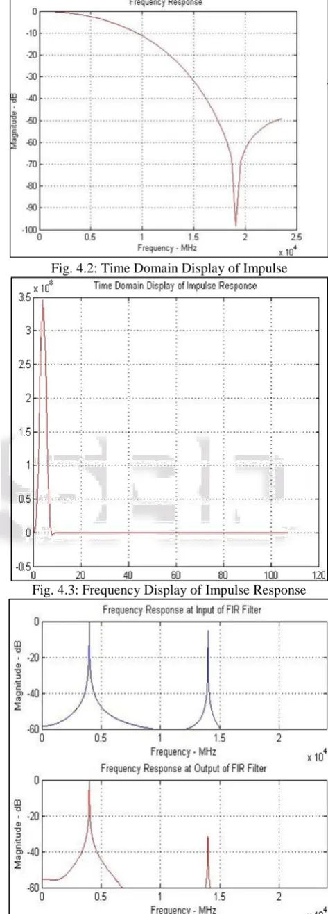
Frequency and Time domain Output waveforms of LPF:
Fig. 4.1: Frequency response of LPF
[image:3.595.44.533.126.748.2]Fig. 4.2: Time Domain Display of Impulse
[image:3.595.44.302.214.472.2]Fig. 4.3: Frequency Display of Impulse Response
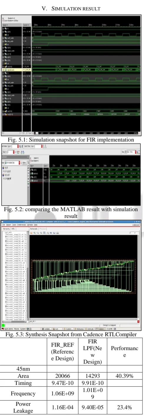
[image:3.595.50.284.566.754.2]V. SIMULATION RESULT
[image:4.595.305.552.62.350.2]Fig. 5.1: Simulation snapshot for FIR implementation
Fig. 5.2: comparing the MATLAB result with simulation result
Fig. 5.3: Synthesis Snapshot from Cadence RTL Compiler
FIR_REF (Referenc e Design)
FIR LPF(Ne
w Design)
Performanc e
45nm
Area 20066 14293 40.39%
Timing 9.47E-10 9.91E-10
Frequency 1.06E+09 1.01E+0
9 Power
Leakage 1.16E-04 9.40E-05 23.4%
Power Active 9.02E-03 9.60E-03 Normalized
power 9.02E-06 9.60E-06
90nm
Area 24866 21939 13.34%
Timing 1.06E-09 1.01E-09 4.66%
Frequency 9.47E+08 9.91E+0
8 Power
Leakage 7.65E-06 7.37E-06 2.83%
Power Active 8.10E-03 8.98E-03 Normalized
power 9.00E-06 8.98E-06
180nm
Area 95141 94802 0.36%
Timing 2.06E-09 1.81E-09 13.53%
Frequency 4.86E+08 5.52E+0
8 Power
Leakage 3.08E-06
3.41E_0
6 10.79%
Power Active 3.53E-02 4.31E-06 22.23% Normalizedpowe
r 7.26E-05 4.74E-05
Table 1: Summary of Synthesis Results
VI. CONCLUSION
Finite impulse response filters are important building blocks for various digital signal processing applications. Recently, because of the increasing demand for video-signal Processing and transmission, high-speed and high-order FIR filters have frequently been used to perform adaptive pulse shaping and signal equalization on the received data in real time, e.g., ghost cancellation, source coding, equalizer, Partial-Response Maximum Likelihood, and channel Equalization. A FIR filter is composed of multipliers and adders, and their performance adders determines the speed of FIR filter.
Primary aspect of this project is to implement the Architecture and Detailed of FIR Filter Design coded in Verilog HDL maintaining industry standard coding guidelines to generate sine wave of variable frequency.
The secondary aspect of the project is to compare the LNS result with the FIR filter based on array multiplier using cadence too land simulation of design, Synthesis strategy documented, Synthesis scripts were coded and design synthesized on 45,90,180nm technology and timing checks performed. Synthesis report with final working frequency, power and area and physical design published in the report.
VII. FUTURE WORK
FIR based hardware units offer substantial performance improvements, at reduced costs, over conventional analog devices. In future work, increases the area and power reduction. Future work can be to check the dependencies of this implementation for different FIR filter Tap and the architecture can also be compared with IIR filter
REFERENCES
[1] B. Edwards, A. Corry, N. Weste, and C. Greenberg, “A Single-Chip Video Ghost Cancel er,” IEEE Journal of Solid-State Circuits, Vol. 28, no. 3,pp. 379–383, Mar. 1993.
[2] J. R. Choi, S. W. Jeong, L. H. Jang, and J. H. Choi, “Structured Designof a 288- Tap FIR Filter by Optimized Partial Product Tree Compression,”IEEE Journal of Solid-State Circuits, Vol. 32, no. 3, pp. 468–476, Mar.1997. [3] J. Pearson, S. K. Reynolds, A. C. Megdanis, S. Gowda, K.
R. Wrenner, M. Immediato, R. L. Galbraith, and H. J. Shin, “Digital FIRFilters for high Speed PRML Disk Read Channels,” IEEE Journal of Solid-State Circuits, vol. 30, no. 12, pp. 1517–1523, Dec. 1995.
[4] W. L. Abbott, H. C. Nguyen, B. N. Kuo, K. M. Ovens, Y. Wong, andJ. Casasanta,
[5] “A Digital Chip with Adaptive Equalizer for PRML Detectionin Hard-Disk Drives,” in Digest of Technical Papers of the 41st IEEEInternational Solid-State Circuits Conference, Feb. 1994.
[6] C. J. Nicol, P. Larsson, K. Azadet, and J. H. O Neil , “A Low-Power 128-Tap Digital Adaptive Equalizer For Broadband Modems,” IEEE Journal of Solid-State Circuits, Vol. 32, no. 11, pp. 1777–1789, Nov. 1997. [7] B. Balaji, K. Balaji, H. Sundararaman, A. Naveen, and K.
R.Santha, “Memory Reduction Techniques for Logarithmic Number System”, Feb. 2007.
[8] J. Detrey and F. de Dinechin, “A VHDL Library of LNS operators,” in Conference Record of the 37th Asilomar Conference on Signals, Systems and Computers, Nov. 2003.
[9] Koren, Computer Arithmetic Algorithms. A K Peters, 2002.
[10]Y. Wan and C. L. Wey, “Efficient Algorithms for Binary Logarithmic Conversion and Addition,” IEE Proceedings— Computer and Digital Techniques, Vol. 146, no. 3, pp. 168–172, May 1999.