Interlocking of Bricks
Adnan Bin Abdul Lateef
1Syed Muqeed Ashmi
2Mohd. Fasahat Ali Mannan
3Mir Abrar Ali
4Sohaib Abdullah Hussaini
5 1,2,3,4,5UG Students
1,2,3,4,5
Department of Civil Engineering
1,2,3,4,5
Lords Institute of Engineering & Technology, India
Abstract— The use of interlocking bricks masonry has gained rapid popularity in many foreign countries as an alternative to conventional bricks for sustainable housing. It has been challenging always for researchers to make interlocking brick light weight, low cost and improve the performance against aggressive environment. An experimental effort has been made in this concern. This paper gives the results of an experimental investigation in which the compressive strength, water absorption and density were investigated by using varying percentage of fly ash, stone dust, and sand with different mix proportion. A manmade fibre, glass fibre reinforce polymer (GFRC) /Steel / Bamboo utilize as reinforcing material to produce the interlocking blocks which gives appreciable results discuss in detail. The experimental results compared with that ordinary burnt clay brick and interlocking brick found durable in aggressive environments and have sufficient strength for their use in sustainable building construction. The basic idea was to build a wall without cement and to bind the bricks together by their interlocking properties attained by the reinforcement (GFRC Bar, Steel bar, and Bamboo).The dimensions of the brick were 12x8x4mm. The composition of the bricks was 75% of fly ash, 20% of cement, 3% of gypsum and 2% of lime. Two rods penetrate inside the standard fly ash bricks from the top and two holes are made adjacent to the rods at the bottom forming a wall with the rods of one brick interconnecting with the holes of the other brick. The bricks can be juxtaposed one over the other. The wall can be assembled and dissembled at any point of time leading to simple and plain sailing construction. The bond used for the wall was stretcher/running bond. Compressive strength of interlock bricks are having ranges between 1.2 N/mm^2 to 2.0 N/mm^2.
Key words: Bricks
I. INTRODUCTION
A. Interlocking of Fly Ash Brick
Solid concrete Lego blocks can be used as a temporary retaining wall system or as a wall separator between different materials such as sand, salt, compost, etc. The benefit of using the interlocking blocks is that they can function as a temporary solution for constructions, as it is possible to move or expand the construction when no casting is required between the blocks. A very high amount of waste is being produced all around the world. The most common method of managing waste is through its disposal in landfills creating in that way huge deposits of waste. In this situation, waste recycling is gaining increasing importance. At present in India, about 206 coals based thermal power plants are producing amounts to be more than 140 billion numbers annually. For fulfill such demand fly ash
interlocking brick may be one of alternative for sustainable construction industry Much experimental research carried out for producing good quality brick with reduction of cost using industrial waste And also for reducing price and increasing the strength many natural and manmade reinforcing material used in the production of bricks. There are a wide range of natural fibres, namely sisal, bamboo, coir (coconut fibre), jute, and many others. In this research work the manmade fibre GFRP introduce as a reinforcing material. The effect of GFRP with maximum percentage of fly ash in interlocking brick is studied. This advocate the use of fly ash as the supplementary material to soil by reducing the consumption of soil in brick manufacturing towards efforts of maintaining ecological balance through sustainable development of natural resources.
These concrete blocks can be assembled to create walls. There is no need for casting when the blocks are inter-locked with each other. The walls stand firmly due to the interlocking of rods in holes. The interlocking blocks are not fixed to the ground. They are stacked on soil or on a concrete slab. The constructed walls can easily be taken apart because there is no casting between the blocks.
II. LITERATURE REVIEW
A paper presented at the 13th World Conference on Earthquake Engineering in Vancouver, Canada by Martin Wieland and R. Peter Brenner proved the structural benefit of this construction method.
Concrete blocks were first introduced in Holland in the fifties as replacement of bricks which had become scarce due to the post-war building construction boom. These blocks were rectangular in shape and had same size as the bricks.
Manz (1982) have suggested that high-calcium fly ashes (the so-called Class C ashes) are best distinguished from the low-calcium (Class F) ashes by their cementing properties.
Puri (1975) has stated that fineness is one of theprincipal parameters to be considered for fly ash to be added to cement, as it influences the rateof development of mechanical strength and relative values to be attained.
Sharma (1990) has classified Indian fly ashes based on the shape of particles, as one of the parameters, m pozolanic activity is noisily recanted the reaction between the 'reactive silica7 of the 4 pozzolona and calcium hydroxide producing calcium silicate hydrate
III. METHODOLOGY
A. Preparation of Mould
1) Special Mould must be prepared for making Interlocking Bricks.
2) It is better to make a Wooden Mould in which we can place a Two Sticks of 3.5inch for providing a hole in the brick.
3) Two types of mould must be required, as to fill the gap with single brick while making a wall.
4) Therefore, Along with a proper size of mould, a small mould should also be prepared to make a small size of brick.
B. Mixing of Materials
1) Materials must be mixed in proper composition. 2) If the composition is wrong, then the weight of the brick
either increases or decreases which effect the strength of the Bricks.
3) Composition of the brick is => Fly Ash = 75%
=> Cement = 20% => Gypsum = 3% => Lime = 2%.
C. Filling of Mould
1) Mould must be filled with proper proportion. 2) Proper amount of material must be filled.
3) Mould should be in proper manner, if there is any kind of damage to the mould, it results in improper size of the brick.
D. Placing of Bars
1) Bars must be inserted while filling the mould. 2) Proper measurement is required to insert the Bar. 3) Bars which are inserted must be parallel to that of the
stick present in the mould which is used for making holes in the bricks.
4) There must be a 3"(inch) gap from the corner to the bar. 5) Bars must be of Size 3.5"(inches)
E. Curing for 14 Hours
1) Curing for 14 hours is required after filling the mould. 2) These results in the Better strength of bricks.
3) After curing, the bricks must be demoulded.
4) Curing for 14 hours are needed after the demoulding process is done, so that the brick should not get disturbed.
F. Demoulding of Bricks
1) Brick must be demoulded after proper curing of 14 hours. 2) While demoulding, proper care must be taken such that
the bricks do not tear apart or broken.
3) After demoulding the bricks, it is necessary to do the Curing again.
G. Curing for 14 Days
1) Curing is required to bring the good strength among the bricks.
2) After the bricks get demoulded, it is necessary to keep the brick for Curing.
[image:2.595.324.532.66.180.2]3) It results in the consistency of bricks which helps in building the proper walls.
Fig. 1: Basic Data of the Structure
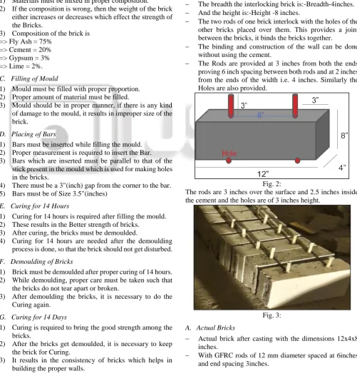
IV. METHODS OF CREATING THE MODEL The dimensions of the brick are as follows:
The length the interlocking brick is:-Length-12inches i.e. (1 feet).
The breadth the interlocking brick is:-Breadth-4inches. And the height is:-Height -8 inches.
The two rods of one brick interlock with the holes of the other bricks placed over them. This provides a joint between the bricks, it binds the bricks together.
The binding and construction of the wall can be done without using the cement.
[image:2.595.46.548.240.775.2] The Rods are provided at 3 inches from both the ends proving 6 inch spacing between both rods and at 2 inches from the ends of the width i.e. 4 inches. Similarly the Holes are also provided.
Fig. 2:
The rods are 3 inches over the surface and 2.5 inches inside the cement and the holes are of 3 inches height.
Fig. 3:
A. Actual Bricks
Actual brick after casting with the dimensions 12x4x8 inches.
[image:2.595.315.542.525.685.2] The height of the rod is 2.5inches over the surface and 3 inches below the surface i.e. total 5.5 inches.
Fig. 4: Casting Process
V. DESCRIPTION OF THE MODEL
A. Bricks with different Reinforced 1) Steel Rod Reinforced
Fig. 5:
2) GFRC Bar Reinforced
Fig. 6:
3) Bamboo Reinforced
Fig. 7:
4) Mould Dimensions
The moulds were custom made moulds according to required dimensions.
The inner length of the mold was 12 inches, inner breadth was 4 inches and the height was 8 inches.
To enable two holes at the bottom of the brick, at an inner spacing of 6 inches and end spacing’s 3 inches- two wooden sticks are attached at the bottom at the required dimensions. The height of the stick is 3 inches, to enable 3 inches hole.
Fig. 8:
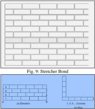
5) Bond Used for Wall Construction
The bond which will be used will be Running/Stretcher Bond. The running bond is the most used bond and is composed of stretchers offset by 1/2 brick per course.
This bond will give the interlocking bricks wall a better strength compared to other bonds.
The point of joining of two bricks meets with the midpoint of the brick over them. Two rods from two different bricks fit in the holes of the single brick. The end of both the bricks i.e. 3 inches after the rod end would lie in the 6inches spacing between the two rods.
[image:3.595.326.530.498.730.2]The brick was divided into 3 parts of 3 inch,6 inch and 3 inch rather than diving it into three equal parts of 4inch,4inch,4inch as this equally divided brick would not enable the interlocking process and the wall could not be constructed.
Fig. 9: Stretcher Bond
Fig. 11: Wall Constructed Using Our Interlocking Bricks
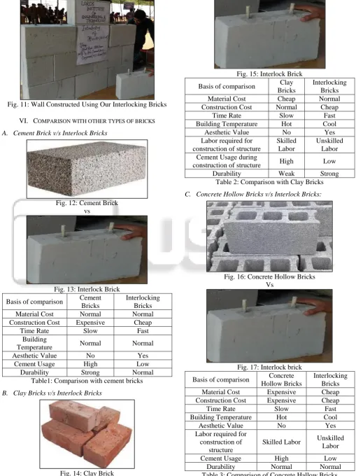
VI. COMPARISON WITH OTHER TYPES OF BRICKS
A. Cement Brick v/s Interlock Bricks
Fig. 12: Cement Brick vs
Fig. 13: Interlock Brick
Basis of comparison Cement Bricks
Interlocking Bricks
Material Cost Normal Normal
Construction Cost Expensive Cheap
Time Rate Slow Fast
Building
Temperature Normal Normal
Aesthetic Value No Yes
Cement Usage High Low
Durability Strong Normal
Table1: Comparison with cement bricks
B. Clay Bricks v/s Interlock Bricks
[image:4.595.69.266.66.216.2]Fig. 14: Clay Brick
Fig. 15: Interlock Brick
Basis of comparison Clay Bricks
Interlocking Bricks
Material Cost Cheap Normal
Construction Cost Normal Cheap
Time Rate Slow Fast
Building Temperature Hot Cool
Aesthetic Value No Yes
Labor required for construction of structure
Skilled Labor
Unskilled Labor Cement Usage during
construction of structure High Low
Durability Weak Strong
Table 2: Comparison with Clay Bricks
C. Concrete Hollow Bricks v/s Interlock Bricks:
Fig. 16: Concrete Hollow Bricks Vs
Fig. 17: Interlock brick
Basis of comparison Concrete Hollow Bricks
Interlocking Bricks Material Cost Expensive Cheap Construction Cost Expensive Cheap
Time Rate Slow Fast
Building Temperature Hot Cool
Aesthetic Value No Yes
Labor required for construction of
structure
Skilled Labor Unskilled Labor
Cement Usage High Low
[image:4.595.42.552.74.755.2]Durability Normal Normal
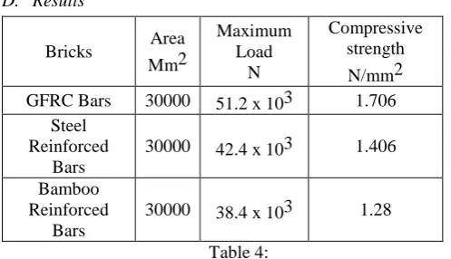
D. Results
Bricks Area Mm2
Maximum Load
N
Compressive strength
N/mm2 GFRC Bars 30000 51.2 x 10³ 1.706
Steel Reinforced
Bars
30000 42.4 x 10³ 1.406
Bamboo Reinforced
Bars
[image:5.595.44.293.73.216.2]30000 38.4 x 10³ 1.28
Table 4: Contact Area = 30000mm2
Compressive strength of GFRC Bar Brick = 1.706 N/mm2
Compressive strength of Steel Bar Brick = 1.406 N/mm2 Compressive strength of Bamboo Brick = 1.28 N/mm2
VII. CONCLUSION
Interlocking fly ash bricks can be used as substitute for normal fly ash bricks as they are quicker in construction and weight almost the same. And the bonding is also almost the same
This kind of interlocking bricks can be majorly used for boundary wall constructions
Interlocking bricks with economically available fly ash in large proportion have sufficient strength for their use in low cost housing, non-load bearing construction and in regions where good quality burnt clay bricks are not available.
The GRFC bars won’t get affected by corrosion, this enables longevity. The weight of the bricks was found to be 5.1 - 5.6 kgs.
Strength of interlocking bricks with increasing fly ash increases with the age
The cement/mortar usage is also less and the construction time is also reduced as the number of days required are also reduce. The number of days reduce also reduce the cost of labor per day
Interlocking Bricks can more efficiently be used as partition walls and boundary walls.
Interlocking bricks with economically available fly ash in large proportion have sufficient strength for their use in low cost housing, non-load bearing construction and in regions where good quality burnt clay bricks are not available.
VIII. STRENGTH OF INTERLOCK BRICKS
Compressive strength of interlock bricks are have ranges between
1.2 N/mm^2 to 2.0 N/mm^2
i.e very good for normal type of constructions ex: Partition walls, Boundary walls & non load bearing walls etc.
The main advantage of this type of brick wall is very stronger to lateral loads compare to other type of brick walls.
REFERENCES
[1] Interlocking concrete blocks, 2011-02-20, 10:42 http://www.c3c.se/pdf/c3c_folder.pdf
[2] Bansal D, ―Interlocking Dry Stacked Masonry‖, 8th International Masonry Conference 2010 in Dresden [3] MY IB-http://www.myib.com.my/
[4] PRATIBHA: INTERNATIONAL JOURNAL OF SCIENCE, SPIRITUALITY, BUSINESS AND TECHNOLOGY (IJSSBT), Vol. 2, No. 2, May 2014 ISSN (Print) 2277—7261 – (INTERLOCKING BRICK FOR SUSTANABLE HOUSING DEVELOPMENT) [5] International Journal for Research in Applied Science &
Engineering and Technology
[6] (Interlocking Brick DesignParadigm for Sustainable Construction)
[7] International Journal of Civil Engineering and Technology (IJCIET), ISSN 0976 – 6308 (Print), ISSN 0976 – 6316(Online) Volume 4, Issue 6, November – December (2013), © IAEM
[8] International Journal of Civil & Environmental Engineering IJCEE-IJENS Vol:13 No:03— (Compression Performance of Walls of Interlocking Bricks made of Iron Ore ByProducts and Cement) [9] A Thesis Submitted for the Degree of PhD at the
University of Warwick—
[10] (DESIGN OF INTERLOCKING BRICKS FOR
ENHANCED WALL CONSTRUCTION