Designing of the CASE Tool to develop Star Schema
using the XML Schema consisting of Clinical Data
Anita Nagar
Manav Rachna College of Engineering Faridabad
Gunjan Chandwani
Manav Rachna College of Engineering Faridabad
ABSTRACT
Data Warehouse is most widely used for data analysis which supports the management’s decision making process. The sources for the Data Warehouse are commonly taken from the online transactional systems in various formats.XML is one of the standard format used to represent and transport the data in web based systems.XML allows easy sharing of data between different internet applications which enhances the decision making in organizations. This paper focuses on conversion method of XML Schema into the Star and Snowflake schema.
Keywords
Warehouse Schema, Schema graph, Elements, XML Schema, Fact table and dimension table.
1.
INTRODUCTION
Data Warehouse is a central data repository that is maintained separately from an organization’s operational databases. Data warehouse systems allow for integration of a variety of application systems. It stores current as well as historical data and are used for creating reports for senior management reporting such as annual and quarterly comparisons. It is a subject-oriented, integrated, time variant and non volatile collection of data in support of management’s decision making which make it different from other repository system such as relational database system, transaction processing system.
Basically multidimensional model is most popularly used to represent the data in Data Warehouse. The multidimensional model is represented commonly by using the Star schema and the Snowflake schema consist of one large central table (Fact table) and other smaller tables (Dimension tables). The schema graph resembles a starburst, with the dimension tables displayed in a radial pattern around the central fact table. Dimension hierarchies are created by joining the dimensions in such a way that the parent dimension consist of foreign key with the same name as the primary key of child dimension. There is another method also available to represent the model which is a Fact constellation schema.
XML is well established standard for semi-structured data and also poses several benefits in web environment. As data could come from various heterogeneous sources so to make them compatible with the Data Warehouse schema and hence in order to integrate these data, they could be converted to XML. Relational Model on the other hand is the most standard and structured way of representing data model. Numbers of researches have been made over the time to map different data models to relational model. XML is also no exception. Proposed work in [1, 2, 3, 4] show different ways of transformation from XML to relational model schema. In this
paper the focus is on converting XML schema to data warehouse schemas based on ROLAP. Thus we are not concentrating on the techniques of converting XML to relational model. Here we refer to some of the existing methods to transfer XML to data warehouse paradigm. XML data is associated with DTD [5] or XML schema [5]. XML provides Document Type Definition (DTD), which explains precisely what elements could appear as document and what the contents of the elements and attributes are. The approaches [7] [8] [9] show how XML data based on DTD have been converted to data warehouse schema. However DTD have some limitations. DTD do not have any built-in data types; also do not support user-derived data types and allow only limited control over cardinality. XML schemas are more powerful to represent XML document structure and overcome the limitations of XML DTD.
Data Warehouse allows integrated data to be processed analytically based on OLAP. So, here we focus on the conversion of XML Schema into the ROLAP due to the limitation of the DTD.[1, 2, 6, 11, 12] have been worked to integrate XML data in Data Warehouse. The paper [6] proposes a method to design multiple cubes of multidimensional model from XML schema. There has been work to convert the contents of XML Schema to the Star schema of Warehouse.
This paper focuses on the conversion of the XML Schema into the Star and Snowflake schema. The paper [12] proposes XML schema conversion to OLAP cube by identifying fact and dimension tables. The paper considers that there is only one root element which excludes the formation of Fact constellation schema as it do not take any connection among different fact tables.
2.
PRELIMINARIES
Schema graph: Schema graph is a way to represent the entities present in XML Schema. It consists of following properties:
a. It consists of different levels.
b. The entities are represented by the vertices.
Holder Element: These are the elements which have no predecessor. They are placed in Level-1 of the graph.
Contained Element: These are the elements which are directly connected to the Holder element. They are placed in Level-2 of the graph.
Secondary Element: These are the elements which are connected to the contained elements. They are placed in Level-3 of the graph.
If further elements have been encountered in the graph connected to the secondary element, they would be placed in Level-4 of the graph. Subsequently new level could be created whenever any elements would appear in the graph. In the Schema graph, all the entities are represented by the Rectangular shape and the attributes are represented through the oval shaped vertex.
Figure1: Schema Graph
3.
METHOD TO CONVERT THE XML
SCHEMA INTO THE WAREHOUSE
SCHEMA
3.1
Overview of the method
There are two basic steps to be followed in order to model the Star Schema from the related XML Schema. In the first step, a Schema graph is formed from the related XML Schema and then in the next step, the fact table and the dimension tables and their relationships are identified. After the identification of relationship, the type of Warehouse Schema will be identified. The elements present in the Schema graph are HE, CE and SE. If any element found to be without any primary key then a new primary key would be added to it to make it unique. The HE would correspond to the fact table and for the entries of the fact table; the primary attribute of the CE’s would get placed in their corresponding to their HE. And furthermore if there would be any SE then it gets placed in the CE’s table.
3.1.1
Example of Star Schema
<xsd:elementname="Treatment_desc" type="xsd:string" use="required"/>
<xsd:elementname="Treatment_cost" type="xsd:decimal" use="required"/>
<xsd:elementname="Equip_code" type="Equip_type" use="required"/>
</xsd:sequence>
<xsd:complexTypename="Equip_type"> <xsd:sequence>
<xsd:elementname="Equip_desc" type="xs:string" use="required"/>
<xsd:elementname="Equip_cost" type="xs:string" use="required"/>
</xsd:sequence>
<xsd:elementname="Doctor_id" type=”Doctor_type”> <xsd:complexType>
<xsd:sequence>
<xsd:elementname="Doc_name" type="xs:string" use="required"/>
<xsd:elementname="Doc_spec" type="xs:string" use="required"/>
<xsd:elementname="Doc_dept" type="xs:string" use="required"/>
<xsd:elementname="Doc_type" type="xs:string" use="required"/>
<xsd:elementname="Doc_fee" type="xs:decimal" use="required"/>
<xsd:elementname="Med_code" type="Med_type" use="required"/>
</xsd:sequence>
<xsd:complexTypename="Med_type"> <xsd:sequence>
<xsd:elementname="Med_desc" type="xsd:string" use="required"/>
<xsd:elementname="Med_price" type="xsd:decimal" use="required"/>
</xsd:sequence>
<xsd:elementname="Ward_no." type=”Ward_type”> </xsd:complexType>
<xsd:elementname="Ward_type" type”xs:string” use=”required”/>
<xsd:elementname="Bed_no." type="Bed_type" use="required"/>
</xsd:sequence>
<xsd:complexTypename="Bed_type"> <xsd:sequence>
<xsd:elementname="Assigned_date" type="xsd:date" use="required"/>
<xsd:elementname="Discharged_date" type="xsd:date" use="required"/>
<xsd:elementname="Bed per day_charge" type="xsd:decimal" use="required"/> </xsd:sequence>
<xsd:elementname="Lab_id" type=”Lab_type”> <xsd:complexType>
<xsd:sequence>
<xsd:elementname="Lab_desc" type="xs:string" use="required"/>
<xsd:elementname="Test_id" type="Test_type" use="required"/>
</xsd:sequence>
<xsd:complexTypename="Test_type"> <xsd:sequence>
<xsd:elementname="Test_price" type="xsd:decimal" use="required"/>
<xsd:elementname="Report_id" type="Report_type" use="required"/>
</xsd:sequence>
<xsd:complexTypename="Report_type"> <xsd:sequence>
<xsd:elementname="Report_desc" type="xsd:string" use="required"/>
</xsd:sequence> </xsd:sequence> </xsd:complexType> </xsd:element> </xs:schema>
3.2
Method to develop the Schema Graph
from the XML Schema(Algorithm)
Find out those entities in XML schema that have no predecessor and denote them as the starting vertices or holders for the entire graph. These entities would be known as HE. They would placed in the Level-1 of the graph.
For all HE (i=1 to n) perform following : (n is the total number of HE)
Find the sequence of elements under ith HE :
If it is an element then create a vertex for it into the graph and connect it with ith HE. These elements (vertices) would be denoted as CE. CE would be placed in the level-2 of the graph.
Else if it is an attribute it would be considered as an attribute of the corresponding HE.
For all CE (j=1 to m) perform following: (m is the number of CE in the HE)
Scan the XML Schema for jth CE:
If it is an element then place it into the graph and connect it with its CE.
These elements would be known as SE. SE would be placed in the level-3 of the graph.
Else if it is an attribute place it would be considered as an attribute of CE.
For every SE (k=1 to p) : (p is the total number of SE at that level)
Repeat the steps to include the entities and attributes as they encountered. Whenever a new entity is added new level is created for it.
End For /* SE */
End For /* CE */
End For /*HE*/
To build the Schema graph, Scan the XML Schema for the elements which are not being nested within any element, are now referred as HE and placed it at level-1 and the elements encountered as a nested element and are directly connected to the HE, are referred as CE’s. If any further element found to be nested within the CE, named them as SE and placed at level-3 or at some lower level as shown in figure below.
Figure2: Example of Schema Graph
3.3
Identification of the Fact table and the
dimension table
When the Schema graph is formed, the entities HE, CE and SE’s are identified. The HE is turned to become the Fact table with the name of HE + “fact” and the CE’s and SE’s would become the dimension tables with their name + “dimension”. In order to maintain the referential integrity, the primary key of the CE dimension would be placed in HE’s Fact table as a foreign key and similarly, the primary element of the SE would get placed in the CE’s Fact table. If in any element table is found to be without primary key, new primary key is then added with the element name + “id”.
3.4
Identification of the type of Warehouse
Schema
There is a procedure to find the type of Warehouse Schema in which the checking of the Relationship between the HE as Fact table and the CE’s and SE’s as Dimension tables in the Schema graph. If there is no further SE’s are encountered under the CE’s then the Warehouse Schema is identified as Star Schema otherwise known as Snowflake Schema.
3.4.1
Procedure Star Schema
The Star Schema is identified, if the Warehouse Schema consists of only the HE and CE’s. The HE fact table consists of primary key of the dimension table as their foreign key. The Algorithm [1] is shown below:
3.4.2
Procedure Snowflake Schema
The Snowflake Schema is identified, if the Warehouse Schema consists of HE, CE and SE also. In addition to the Star Schema there is a primary key of SE which is placed in their corresponding CE above connected to it. If there is some further SE’s present in the Schema graph then the primary keys of them get placed in their immediate previous level SE. The Algorithm is shown:
Partition the Schema Graph Level wise.
Identify HE
For HE:
a)Form a Fact-Table with the name of HE +”Fact” and Primary key of the HE. b)Specify the CE connected with this HE and
3.4.3
Example
The Warehouse Schema builds from the above example (Figure2)
Figure 3: Example of Warehouse Schema
3.5
EXPERIMENTAL RESULTS
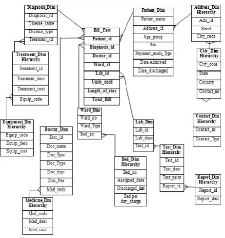
[image:4.595.315.542.62.548.2]After implementing the algorithm mentioned in section B, we get the result which is shown in figure 5 and before this we need to design an interfaces for browsing the XML Schema shown in figure 4 and prove the validation of XML Schema to show whether the syntax of XML Schema is appropriate or not and the checking of data to be saved in database is also done during this stage. Then a window pops up to provide the user a choice of selecting the button labeled as Schema graph or Star Schema. On pressing that button labeled as Schema graph, a Schema graph of given XML Schema is shown on the screen. Consequently, on selecting the option of Star Schema, a Star Schema is built against the Schema graph, drawn in figure 5, by using the algorithm mentioned in section D. The Star Schema is shown in figure 6.
[image:4.595.58.261.69.254.2]Figure 4: Browsing of the Document
[image:4.595.58.289.305.550.2]Figure 5: Schema Graph
Figure 6: Star Schema
4.
CONCLUSION
This paper focuses on the CASE Tool, identifies the Star Schema and the Snowflake Schema from the related XML Schema which consists of the structure of the XML document consists of clinical data in above figure. More Often the XML is chosen as the data source to be transported over the internet between various Web applications and here specifically facilitated the transferring of data in XML format from various heterogeneous data sources to the Warehouse Schema. Data present in these heterogeneous data sources in the form of XML Schema and after going through the ETL phase. The Warehouse kept the contents of XML Schema in the form of their Schema. In order to form the Warehouse Schema, the CASE Tool in this paper will be used to convert the XML Schema into the appropriate Warehouse Schema. This approach can be helpful in the business intelligence in organizations to build the Warehouse Schema in short duration as the proposed methodology cab be applied on to the changes in the XML sources whenever needed and quickly build the Warehouse Schema corresponding to that change.
Partition the Schema Graph Level wise. Identify the HE
For each HE:
Form a Fact-Table with the name of HE + ”Fact” and primary key of the HE.
Specify the CE connected with this HE, include the primary keys of each CE into the Fact-Table. For each CE find SEs, if any. If found Connect it with its CE using the primary key of the SE. For each SE:
Check if there is any SE:
If further level of SE is found the primary key of the new SE of the immediate higher level is placed in the SE of current level.
5.
REFERENCES
[1] Soumya Sen, Ranak Ghosh, Debanjali Paul, Nabendu Chaki; "Integrating Related XML Data into Multiple Data Warehouse Schemas"; Proc. of the First International Conference on Information
[2] Sarbani Dasgupta, Soumya Sen, Nabendu Chaki; "A Framework To Convert XML Schema to ROLAP"; Proc. of 2nd Intl. Conf. on Emerging Applications of Information Technology, 2011.
[3] Yuan Sun; Hexin Chen; Mianshu Chen; Xinying Wang; Aijun Sang; “Multi-dimension Multimedia Retrieval Model Implementation Based on XML Database” International Conference on Signal Processing Systems, 2009.
[4] Rajugan, R.; Chang, E.; Dillon, T.S.; “Conceptual Design of an XML FACT Repository for Dispersed XML Document Warehouses and XML Marts”, 5th International Conference on Computer and Information Technology, 2005.
[5] Tim Bray, Jean Paoli, C. M. Sperberg-McQueen, Eve Maler, François Yergeau; “Extensible Markup Language (XML) 1.0 (Fifth Edition)”; W3C Recommendation; www.w3.org/TR/RECxml.
[6] Parimala N and Payel pahwa; “From XML schema to cube” International Journal of Computer Theory and Engineering; Vol. 1, No 3 August 2009.
[7] Boris Vrdoljak, Marko Banek, and Stefano Rizzi: Designing Web Warehouses from XMLSchemasY. Kambayashi, M. Mohania, W. Wöß (Eds.): LNCS 2737, pp. 89-98, 2003
[8] Wolfgang Hummer, Andreas Bauer, Gunnar Harde: XCube – XML for Data Warehouses, DOLAP’03, November 7, 2003, USA.
[9] M. Golfarelli, S. Rizzi, and B. Vrdoljak, .Data warehouse design from XML sources., Proc. DOLAP’01, Atlanta, pp. 40-47, 2001.
[10] Data Mining Concepts and Technique,2nd Edition, Jiawei Han and Micheline Kamber, Morgan Kaufmann Publisher.
[11] Payel pahwa and Parimala N; “Conceptual design of data warehouses from xml schemas” 2nd
International Conference on Intellectual Capital, knowledge management & Organizational Learning 21-22 Nov, 2005 American University of Dubai, United Arab Emirates.
[12] M. Jensen, T. Møller, and T.B. Pedersen, .Specifying OLAP Cubes On XML Data., Journal of Intelligent Information Systems, 2001.
[13] Ramanath, M.; Kumar, K.S.; “A rank-rewrite framework for summarizing XML documents” 24th
International Conference on Data Engineering Workshop, ICDEW 2008
[14] Rajugan, R.; Chang, E.; Dillon, T.S.; “Conceptual Design of an XML FACT Repository for Dispersed XML Document Warehouses and XML Marts”, 5th International Conference on Computer and Information Technology, 2005.