20
Moving Object Detection and Segmentation using Frame
differencing and Summing Technique
Gopal Thapa
Department of Computer Application Sikkim Manipal Institute of
Technology
Kalpana Sharma
Department of Computer Science and Engineering Sikkim Manipal Institute of
Technology
M.K.Ghose
Department of Computer Science and Engineering Sikkim Manipal Institute of
Technology
ABSTRACT
The technology of motion detection has become one of the important research areas in computer vision. In surveillance video this has got a number of applications which range from indoor and outdoor security environment, traffic control, behavior detection during spot activities and for compression of video. In this paper simple but robust moving object detection and segmentation algorithm is proposed. The algorithm is based on the background subtraction. A differencing and summing technique (DST) has been used for the moving object detection and segmentation. This method is simple and low in computational complexity as compared to traditional object identification and segmentation techniques. The experimental results show that the proposed method work efficiently in identifying and segmenting moving objects, both in indoor as well as in outdoor environment with static background.
General Terms
Object Identification, Object Segmentation, Surveillance video.
Keywords
Object identification, Object segmentation, background subtraction, surveillance video, bonding box.
1.
INTRODUCTION
Moving object segmentation in real world scene has become one of the important research areas in computer vision. This has got a number of applications in video surveillance. These include indoor and outdoor security environment, traffic control, and behavior detection during spot activities and for compression of surveillance video. Reliable detection of moving object is an important requirement for such applications. In literature, four different kinds of approaches can be found for solving the object segmentation problems- background subtraction, temporal differencing, statistical method and optical flow.
Background subtraction [1][2] , is the commonly used class of technique to detect moving region in image. This method is highly dependent on a good background model to reduce the influence of dynamic scenes. Temporal differencing [3][4] makes use of pixel by pixel difference between two or three consecutive frames in an image sequence to extract moving objects. This is very adaptive to dynamic environment but generates holes inside the moving objects.
Optical flow [5][6] based motion segmentation uses characteristics of flow to detect independently moving objects even in the presence of camera motion. However most flow
methods are computationally complex and very sensitive to noise.
Statistical methods [7][8][9] are inspired by the basic background subtraction method. These methods are proposed to extract change regions from stationary background. The statistical approaches use the characteristics of individual pixels or group of pixels to construct more advance background models which can be updated dynamically. Each pixel in the current image can be classified into foreground or background comparing the statistics of the current background model.
In [10], a novel approach to segment the motion object using statistical partial correlation method. Motion segmentation is done by checking pixel by pixel disparity in RGB color space between three consecutive video frames simultaneously. A distance measuring factor is used to classify a pixel p(x,y) as background. This algorithm is claimed to be robust to large variation in intensity. However because of pixel to pixel analysis, the complexity is high.
Based on background subtraction, statistical methods are proposed to extract moving region from background in [7][11]. Background statistics are dynamically updated during processing of the video signal. Current image pixels are classified into foreground or background based on the statistics of the current background model.
In [12] a novel hybrid algorithm for segmentation of slowly moving objects is proposed. The algorithm is based on temporal information of the difference among multiple frames to detect initial moving regions. Gaussian mixture model (GMM) is then used along with an expectation maximization algorithm to segment a spatial image into homogeneous regions. Final moving objects are obtained by fusing the result of motion detection and spatial segmentation.
2.
PROPOSED SCHEME
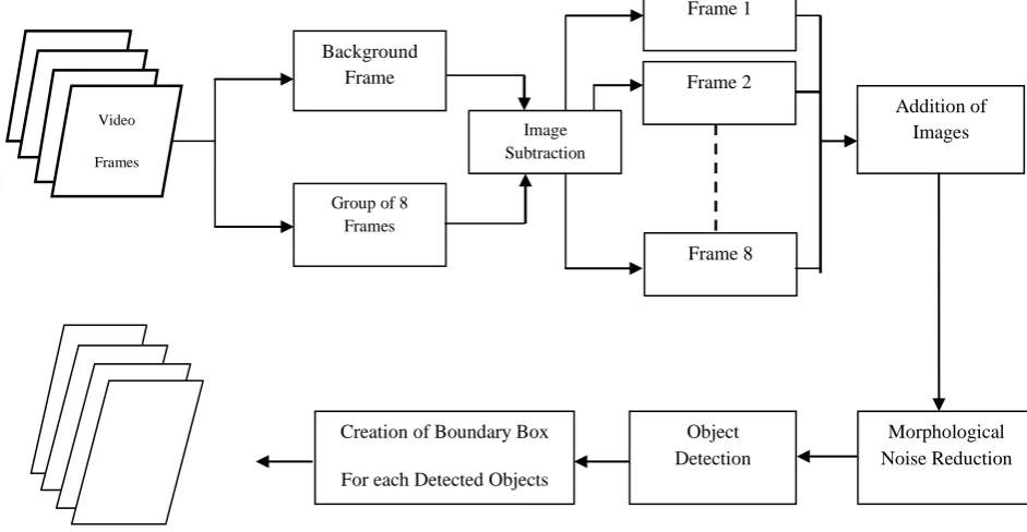
In surveillance domain, videos usually consist of objects that are smaller in size as compared to the background and these objects are fast moving. Generally there are multiple objects in the scene and they have frequents occlusion with each other [13]. Therefore, if a group of frames from a video signal is subtracted from the background and the resultant difference frames are added together, the maximum displacement of the objects within the group of frames can be computed. Based on this maximum displacement each of the objects can be identified. Motivated by this fact, a new moving object identification and segmentation is proposed in this paper. The block diagram for the proposed algorithm is show in Fig.1.
2.1
Moving object detection
The differencing and summing technique (DST) is used for identifying moving objects and the objects are segmented from the background using bonding box based on the maximum and minimum coordinates of the moving objects. This technique is based on the background subtraction. To detect the moving objects in video frames, initially, the model of background scene must be constructed, and then current frame is subtracted from the background model in order to determine the moving objects. Here it is assumed that the background image has been constructed using any of the methods used in [8][9][10]. Firstly eight consecutive frames from a video signal are considered and each of them is subtracted from the background image. The difference images are them added together to obtain a resultant image. This image represents the maximum movement of the objects in the given eight frames.
Let be the sequence of frame from a video signal then the equation 1 represent the difference of the image sequence with the background image f(x,y) and equation 2 represent the sum of difference image.
Here represent the moving object in each frame. The summation of the entire difference image results in an image which shows the maximum displacement of an object in the given sequence of frames. The noise is removed from the resultant image using morphological opening and closing process. The final image is threshold to obtain the binary image. This final image is a black and white image that consists of black background with the objects along with its displacement denoted by white connected pixels. The summery of the algorithm is described below.
STEP 1: Read 8 consecutive frames from a video sequence. STEP 2: If it is a RGB image convert it into grayscale image. STEP 3: For Frame: = 1 to 8, do
3.1: If Frame < = 8, then
Frame: = Frame – Background [End For]
STEP 4: Add all the 8 results obtained in STEP 3.
STEP 5: In the image obtained in STEP 4, fill all the gaps inside the object.
STEP 6: Convert the image obtained in STEP 5 into a binary image.
STEP 7: Remove all the extra noises from the image obtained in STEP 6 using morphological opening operation
[image:2.595.88.559.462.706.2]The resultant image is the image depicting the objects and the region covered by the individual objects in all the 8 frames, which gives the maximum displacement by the object within the group of 8 frames. After the maximum displacement of an object is identified, the next stage is to find the rectangular bounding box covering the region of maximum displacement for each object.
Fig 1: Block diagram for the segmentation of moving objects from the frames.
Object Detection
Morphological Noise Reduction Background
Frame
Addition of Images
Group of 8 Frames
Creation of Boundary Box
For each Detected Objects
Video
Frames
Image Subtraction
Frame 1
Frame 8 Frame 2
22
2.2
Object segmentation – Bonding box
creation
For segmenting the moving object from the video frame the concept of 8 neighbor’s connectivity of pixel is used. With this concept pixels of the objects are labeling in order to segment them. Here, it is assumed that if the pixels are connected then they belong to the same object and hence given the same label.
The labeling procedure starts by scanning the individual pixel. Scanning is done one row at a time starting from the top left corner of the image i.e. from left to right of an image. Once the scan reaches the second row the scanning is done in the reverse manner i.e. from right to left, and so on till all the rows of the image matrix are scanned. This means the odd rows are scanned from left to right and even rows are scanned from right to left. As the image is in the binary format the object is denoted by connected pixels with value 1 and the remaining background is denoted by 0. During scanning, labeling of the pixels will not start until the first ‘1’ is encountered. Once the first ‘1’ is encountered it is assumed that the first object is found and now the labeling process can be started. Let p denote the encountered pixel during the initial scan when no object has been detected, if p=1, the pixel p is labeled with a new label followed by the labeling of its entire eight neighborhood pixels with the same label as that of p. This labeling is done to differentiate the different objects. After the first pixel labeling it is know that the object has been detected but the area of the object is yet to be known. To know the exact dimension of the object, pixels on the same row are scaned, if the pixel p=1 again the same labeling process is followed. The scanning technique for detection of single object is illustrated in the Fig 1.
Fig 2: Pixel Scanning Process and first pixel leveling.
Figure 3: Second pixel labeling.
[image:3.595.346.524.367.716.2]Figure 3: Second pixel labeling.
Fig 3: Second pixel labeling.
Fig.2 shows the first iteration scanning process where the initial pixel p=1 is found and the corresponding eight neighborhood is labeled with a label ‘v’. If any one of the neighbor is already labeled which denotes that there is an existing object already present than the existing label is used to label the entire eight neighborhood of current pixel. This denotes that the scanned pixel belongs to the existing object.
Fig.3 illustrates the first iteration scanning process where the next pixel p is also 1 that is already labeled but we still need to label its neighborhood pixels that are yet to be labeled. The eight neighborhood of 1 is scanned and the label that is assigned to any one of its eight neighborhoods is assigned to the non-labeled pixels. This technique isolates the connected pixels of each object by assigning them with the same label. As the object is a represented by a group of connected pixels this process differentiate between objects using the label.
[image:3.595.351.519.378.562.2]Fig.4 shows that the next pixel p=0 and if any of the surrounding eight neighboring pixels contains a white pixel (p=1), then the same procedure is followed i.e. eight neighborhood of 0 is scanned and the label that is assigned to any one of its eight neighborhoods is assigned to all its non-labeled neighborhood pixels. If in case the eight neighborhood of 0 pixel contains only black pixels (p=0) whether labeled or non- labeled, skip the current pixel and move scanning to the next pixel. By doing this we skip labeling the black pixels which may be the empty spaces inside the frame and which is not the part of the object itself.
[image:3.595.42.282.431.741.2]Fig 4: Third pixel labeling.
Fig 5: Fifth pixel labeling
In the Fig.5 where pixel p=0, the every neighboring pixels are already labeled in previous step. Here the labeling in not required so the second iteration starts in the reverse order and the same labelling process is carried on as shown in Fig.6. 0 0 0(v) 1(v) 1(v) 0 0
0 1 1(v) 1(v) 1(v) 1 1
0 0 1 0 1 1 0
0 0 0 0 0 0 0
0 0 0 0 0 0 0
0 0 0 0 0 0 0
0 0 0 0 0 0 0
0 0 0(v) 1(v) 1(v) 0(v) 0
0 1 1 1(v) 1(v) 1(v) 1
0 0 1 0 1 1 0
0 0 0 0 0 0 0
0 0 0 0 0 0 0
0 0 0 0 0 0 0
0 0 0 0 0 0 0
0 0 0(v) 1(v) 1(v) 0(v) 0(v)
0 1 1(v) 1(v) 1(v) 1(v) 1(v)
0 0 1 0 1 1 0
0 0 0 0 0 0 0
0 0 0 0 0 0 0
0 0 0 0 0 0 0
0 0 0 0 0 0 0
0 0 0(v) 1(v) 1(v) 0(v) 0(v)
0 1 1(v) 1(v) 1(v) 1(v) 1(v)
0 0 1 0 1 1 0
0 0 0 0 0 0 0
0 0 0 0 0 0 0
0 0 0 0 0 0 0
[image:3.595.353.521.543.714.2]Fig 6: Scanning the second row of pixel.
A condition may arise that if the current pixel is a black pixel or p=0 and the surrounding eight neighborhood pixel may contain combination of white and black pixels, if these pixels are not labeled than simply avoid labeling them, else if any one of the 8 neighbors is 1 and its labeled than as mentioned above the same level is assign to all the surrounding eight neighborhood and the current pixel itself. This condition applies only if the current pixel scanned is 0.
Fig 7: Complete labeling of an object.
All the connected pixel of the first detected object is labeled as ‘v’ as shown in the Fig.7 as per the proposed scanning process. Here the labeling stops at fifth row first column where the current pixel value is p=0. Here since all the neighbors of the p is 0, and as stated above for this condition the labeling of the pixel is skipped. Since all the remaining pixel fall under same condition the labelling process is skipped.
For multiple object detection the same procedure is followed. But for multiple objects the labeling for next object is initialized only when the current pixel p is 1 and none of its neighbors are labeled. When such condition arises we further increase the neighbor search range by 10 pixels in all the four sides of the current pixels. This increase of search space is done in order to avoid any empty gaps inside the object which may be misinterpreted as the blank space though this space is the part of the object and should not be neglected, as it may result in the white pixel to be treated as the new object. Now after increasing the search range, it is again checked if any pixel within the search range has been labeled or not, and if any labeled pixel found then the current pixel is treated to be the part of the same object and assign the same label to the current pixel and its neighbors. If none of the pixels in the
search area has been labeled then it can be assumed that the current pixel is a new object and new label is assign it to the current pixel and its neighbors. And the rest of the pixels labeling process is same as mentioned above.
This process of scanning the pixels and labeling is carried out for all the pixels in the image. By this labeling process, different objects will have different labels and hence it is possible to identify each and every object in the frame. Using the maximum and minimum coordinate values of same labelled object a bonding box is created in order to segment the moving objects. As most of the valid objects consist of many connected pixels while the noise is simple consist of limited number of connected pixels. So noise compared to object has less number of labels, so any labels having the lesser counts than the defined threshold are treated as the noise and are neglected. This way actual moving object can be distinguished from noise.
The proposed algorithm can be summarized as follows:
STEP 1: Scan the image one pixel at a time starting from the top-left corner unless the first 1 is encountered. Let the scanned pixel is P.
STEP 2: If P is the first ‘1’ encountered, then label the pixel P and all its 8-neighbors pixels with the same label. Then scan next pixel P.
STEP 3: 3.1: If P=1, then scan the 8-neighbors of P.
3.1.1: If any of the neighbors of P has been already labeled then assign that label to P and all its neighbors.
3.1.2: Else if none of the neighbors of P has been labeled, then
3.1.2.1: Increase the search area by 9 pixels on all four sides of P and start the scan, if any pixel has a label or not. Let the scanned pixel be P’.
3.1.2.2: If any P’ has a label then assign that label to P and all the neighbors of P. Then scan the next pixel P and go to STEP 3.
3.1.2.3: Else if none of the P’ has a label, then assign a new label to P and all its neighbors. Then scan the next pixel P and go to STEP 3.
[End if]
[End if]
3.2: If P=0, then scan the 8-neighbors of P.
3.2.1: If any of the neighbor of P is ‘1’, then check whether that neighbor has been labeled. If yes then assign that label to P and all its neighbors. Then scan the next pixel P and go to STEP 3.
3.2.2: If all the neighbors of P is ‘0’, then scan the next pixel P and go to STEP 3.
[End if]
STEP 4: For each individual label find the minimum (x, y) coordinate and maximum (x,y) coordinate among all the pixels labeled.
0 0 0(v) 1(v) 1(v) 0(v) 0(v)
0 1 1(v) 1(v) 1(v) 1(v) 1(v)
0 0 1 0 1 1(v) 0(v)
0 0 0 0 0 0 0
0 0 0 0 0 0 0
0 0 0 0 0 0 0
0 0 0 0 0 0 0
0(v) 0(v) 0(v) 1(v) 1(v) 0(v) 0(v)
0(v)1(v) 1(v) 1(v) 1(v) 1(v) 1(v)
0(v) 0(v) 1(v) 0(v) 1(v) 1(v) 0(v)
0(v) 0(v) 0(v) 0(v) 0(v) 0(v) 0(v)
0(v) 0(v) 0(v) 0(v) 0(v) 0(v) 0(v)
0 0 0 0 0 0 0
[image:4.595.79.258.328.504.2]24
3.
EXPERIMENTAL RESULTS
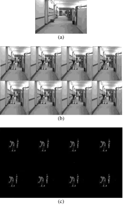
In this section, several experiments were performed to prove the feasibility of the proposed moving object identification and segmentation algorithm. Both the indoor and outdoor environment video has been experimented. Three test videos namely “hall_monitor.avi”, “outdoor.avi” and “road_side.avi” are used in the experiment. The Fig.8 shows the background image, the consecutive eight frames and their corresponding results of subtraction with background for the video signal “hall_monitor.avi”.
(a)
(b)
(c)
Fig 9: (a). Background frame (b). Group of eight consecutive frames (c). Difference of background frames
and the eight frames.
The difference images are added to form a resultant image as shown in Fig.10(a). Based on the maximum and minimum coordinates of the identified moving objects present in the resultant image, a bonding box is created in each of the object which segments it from the stationary background. Fig.11(b) shows the created bonding box.
[image:5.595.315.533.127.220.2]Similarly the results for the other two video signals “outdoor.avi” and “road_side.avi” are shown in Fig.12 and Fig.13. Here a group of eight frames is considered so that so the bonding box does not cover a large displacement. The labels whose pixels count is less than 400 pixels were neglected because these are very small as compared to the image size and are considered as noise. The results
obtained show that the proposed method work efficiently in identifying and segmenting moving objects both in indoor as well as in outdoor environment with static background.
(a) (b)
Fig 10: (a) Image showing object’s maximum displacement within 8 frames (b) Creation of rectangular
bounding boxes covering the region of maximum displacement by the object.
(a) (b)
Fig 11: (a) Object’s maximum displacement within 8 consecutive frames. (b) Creation of rectangular bounding
boxes covering the region of maximum displacement by the object.
(a) (b)
Fig 12: (a) Object’s maximum displacement within 8 consecutive frames. (b) Creation of rectangular bounding
boxes covering the region of maximum displacement by the object.
4.
CONCLUSION
[image:5.595.68.267.184.522.2] [image:5.595.315.542.279.395.2]5.
REFERENCES
[1] Joshua Migdal and W.E.L. Grimson, “Background Subtraction Using Markov Thresholds”, Application of Computer, 2005. pp. 56-65.
[2] Chin-Jung Pai, “Padestrain Detection and Tracking at Crossroads”, IEEE ICIP 2003,pp.101-104.
[3] N.Thome, “A robust Appearance Model for Tracking Human Motions”, Advanced Video and Signal Based Surveillance 2005, pp.528-533.
[5] S.Denman, “Adaptive Optical Flow for Person Tracking’, IEEE DICTA-2005.
[6] Daniel Freedam, M.W. Turek, “Illumination-Invariant Tracking via Graph Cuts”, IEEE CVPR June2005, vol.2 pp.10-17.
[7] Steven Chen, “A MultiScale Parametric background Model for Stationary Foreground Oabject Detection”, IEEE Workshop on Motion and Video Computing, 2007.
[8] Mohand Said Allili, “A Robust Video Foreground Segmentation by Using Generalized Gaussian Mixture Modeling”, IEEE ICIP, 2008
[9] L. Havasi, “Segmentation and Tracking of static and moving objects in video surveillance scenarious”, IEEE CRV, 2007, pp.503-509.
[10] R. Girisha, S.Murali, “Segmentation of Motion Object from Surveillance Video Sequences using Partial Correlation.”, IEEE ICIP 2009, pp. 1129-1132.
[11] Jaime Gallego, “Segmentation and Tracking of static and moving objects in video surveillance Scenarios”, IEEE ICIP 2008.
[12] Z.Zhu, Y.Wang, “A Hybrid Algorithm for Automatic Segmentation of Slow Moving Objects”, AEU-Int. Journal of Electronics and Communications, 2012 vol.66, pp.249-254.