Automated Air Baggage Security Enhancements with
Biometric Recognition using Programmable Logic
Controller
D.Anitha
Jebakumari,Assistant Professor, St.Joseph’s College
of Engineering
Kirthini Godweena. A, ME
Control & Instrumentation
Kavyaa.R
Cognizant Technology Solutions
ABSTRACT
This work intends to automate and provide a secure, human intervention- free air baggage security cum access system. The project aims to automate, minimize and quicken the process of air baggage handling and also reduce the discrepancies involved. The simulation has been explained in four phases. The first phase shows the RFID tag generator along with the fingerprint sensor. The second phase shows how the baggage is diverted according to the RFID tags to the respective airplanes. The third phase illustrates how the baggage is being transported to the airplanes using a long ramp like conveyor.The fourth phase illustrates the process being carried out at the destination. As for the hardware model, the hardware components such as PLC, RFID, conveyor, Finger-print sensor have been identified.The present conveyor however is made resistant to abrasion and impacts and observes the feature of quiet running. Concerning the model prototype set, a modular plastic conveyor is used. The PLC identified is defined for twelve inputs and eight outputs. The RFID is designed using the PIC microcontroller.
Keywords
Bag Handling, RFID, PLC, Finger print sensor, Robot arm, air baggage.
1.
INTRODUCTION
As the global economy grows and the pace of business transactions accelerates, the air transport industry faces greater challenges and demands. Customer expectations for shorter delivery times and better availability of in-transit service continue to grow[8]. To meet these ever-increasing demands, the air transport industry must provide higher levels of service and guarantee higher levels of security. A baggage handling control system is a type of conveyor system installed in airports that transports checked luggage from ticket counters to areas where the bags can be loaded onto airplanes. A BHCS also transports checked baggage coming from airplanes to baggage claims or to an area where the bag can be loaded onto another airplane.
Although the primary function of a BHCS is the transportation of bags, a typical BHCS will serve other functions involved in making sure that a bag gets to the correct location in the airport. The process of identifying a bag, and the information associated with it, to make a decision on where the bag should be directed within the system is known as sortation.In addition to sortation, a BHS may also perform the following functions; Detection of bag jams, Volume regulation (to ensure that input points are controlled to avoid overloading system), Load balancing (to evenly distribute bag volume between conveyor sub-systems), Bag
counting, Bag tracking and Redirection of bags via pusher or diverter. There is an entire process that the BHS controls. From the moment the bag is set on the in-bound conveyor, to the gathering conveyor, through sorting until it arrives at the designated aircraft and onto the baggage carousel after the flight, the BHS has control over the bag.
For airports and airlines, what looks like a deceptively simple task is getting ever more complex as lengthy security procedures, worsening airport congestion, increased interlining and mounting passenger and baggage volumes delays and complicate handling procedures. Routing more traffic through central hubs also means that small problems at one site can rapidly snowball out of control, affecting baggage and passenger transfers at other destinations down the line. Such problems can be removed making use of state of the art technology and knowledge.
According to the statistics of IATA in 2010[6,7], this industry has incurred over US$ 2.5 billion damages arising from the missing of passengers’ luggage. The development of the transport industry has caused many substantial changes in the world as compared to the past. And by considering this point, we come to the conclusion that airports will be substantially changed compared to the past. Generally, an airport can be defined as a system that is to say, in this system, all components should properly and together work to achieve a common objective. If one of these components fails, the whole system becomes disordered or does not reach its favorite results. Baggage Handling Control System (BHCS) is one of the most important components of an airport, which can be alone defined as a system.
bar-coded tags in the installation was a part of the problem, it was one of several technical reasons for the delayed opening. Nevertheless, automated sorting of baggage using laser scanner arrays, known as automatic tag readers, to read bar-coded bag tags is standard at major airports. Bar codes cannot be automatically scanned without direct sight and undamaged print. Forced by reading problems with poorly-printed, obscured, crumpled, scored or otherwise damaged bar codes, some airlines have started using radio-frequency identification (RFID) chips embedded in the tags.
2. THE PROPOSED SOLUTION
The technology was first used in the World War II to identify enemy’s warplanes. But, now, with this technology becoming widespread, it is widely used in customer supply chain, goods inventory tracking, management, libraries, agriculture, medical affairs and many other fields. The technology can change a tagged element into an intelligent and dynamic tool connecting it to an organizational information structure. With this technology being used, the disadvantages of traditional system have been largely removed. Meanwhile, with its precision in reading tags and its ability to identify several items at a time, it will chiefly increase the speed, efficiency and precision of the system in transporting baggage. One of the major problems in the airports which has caused irreparable damages to airlines is the missing of passengers’ baggage and/or their mistakenly transport. This technology can be easily used to pursue all the baggage in airports and even planes to avoid their mistaken transfer. RFID is considered not only as an acceptable, cost effective and new candid for identifying objects, but also as a reliable tool to track at different stages along an air supply chain. In the transport of baggage, RFID tags are used to raise the ability to track the baggage, their transport. And as a result these tags increase the management effect as well as customer satisfaction.
RFID integrated along with PLC and Biometric Recognition such as Finger-print recognition or Retinal Recognition proves to be an efficient solution. Through this double – checking mode benefits obtained are tremendous.
The PLC (Programmable Logic Controller) acts as the main controller from the beginning to the end. Since it is easily programmable, it can be easily tailored for the specific application. The use of biometric security systems in airport passenger handling processes has been widely discussed since 2001, when the terrorist attack on New York brought the world’s attention to security at airports. And yet iris scanning or fingerprint recognition technology has been confined largely to the control of employees accessing restricted areas. Now, however, programmes in the US and Europe are bringing biometrics firmly into the passenger domain. Now it is being extended to being used as an e-passport.Herethe Finger-print recognition is used to initiate the secure baggage handling process thereby providing access to the passenger to place his bag on the conveyor. It is matched with the passenger details including the boarding pass details in the database.
Also while retrieving the baggage at the destination, the passenger is again required to produce a finger-print match to ensure safety.
3.
HARDWARE DESCRIPTION
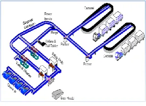
[image:2.595.354.503.276.384.2]Conveyor: Bags are placed by the airline employees on some type of conveyorbelt out of sight of the passengers.In a single-level system, the belt will deliver bags into the terminal from an opening in the wall. The belt generally runs along the wall for a short distance and then turns into the terminal forming a long oval that allows many passengers to access the belt. The belt continues back to the loading area through a second opening in the wall.In a multi-level system, the bags are generally loaded from above or below the carousel and then delivered onto a moving oval-shaped carousel. It is common for this type of system to have two delivery belts, increasing the speed with which bags can be delivered to the passenger level.There is also a variety of carousel that is a combination of the two systems. Bags are loaded from an upper level and end up on a revolving oval, as is normal. However, the very back portion of the oval, in this case, runs in and out of the wall, so it can be accessed by baggage handlers.
Fig.1. Conveyor belt network in Airport
The above figure is a depiction of the conveyor belt network in an airport. The conveyor belt maybe made of rubber, aluminium, steel, alloy finish, plastic and many other durable materials.The basic requirements of a good conveyor belt are as follows;
Abrasion resistant Corrosion resistant Durable
Flexible
Maintenance-free
PLC: The PLC chosen for the prototype depending on the inputs and outputs involved is Delta DVP28SV[12]. 28SV is a 28-point (16 input + 12 output) PLC MPU, offering various instructions and is with 16K Steps program memory, able to connect with all SS/SA/SX/SC/SV series extension models, including digital input/output (max. 512 input/output extension points), analog modules (A/D, D/A transformation and temperature units) and all kinds of new high-speed extension modules.
Its 4-group high-speed (200 KHz) pulse outputs and the two new 2-axis interpolation instructions satisfy all kinds of applications. DVP28SV is small in size and easy to install.
RFID: RFID systems have three main components as shown in Figure 2.
The tag: RFID tags are chips embedded in items which store and transmit information about these items. Most RFID tags store data that identifies a specific item[2].
a cable or wireless connection for storage, interpretation and action.
[image:3.595.58.260.116.281.2]Fig. 2. Components of RFID
[image:3.595.53.269.296.466.2]Fig. 3 circuit diagram of an RFID device
Fig 3 is the circuit diagram of an RFID device. The controller d for the RFID reader is PIC16F87X
.
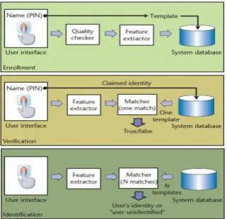
Finger-print sensor:A biometricsystemis essentially a pattern-recognition system that recognizes a person based on a feature vector derived from a specific physiological or behavioural characteristic that the person possesses. Depending on the application context, a biometric system typical lly operates in one of two modes:
Verification or identification. In verification mode, the system validates a person’s identity by comparing the captured biometric characteristic with the individual’s biometric template, which is restored in the system database. Identification can also be used in positive recognition for convenience. While the traditional methods of personal recognition such as passwords, PINs, keys, and tokens work for positive recognition, only biometrics can be used for negative recognition. Fig. 4 contains block diagrams of a verification system and an identification system, both performing the task of user enrollment. The enrollment module registers individuals into the biometric system database.
Fig. 4 Block Diagram of a verification system
During the enrollment phase, a biometric reader (such as a fingerprint sensor) first scans the individual’s biometric characteristic to produce its digital representation. The system generally performs a quality check to ensure that successive stages can reliably process the acquired sample. To facilitate matching, a feature extractor processes the input sample to generate a compact but expressive representation, called a template. Depending on the application, the biometric system might store the template in its central database or record it on a smart card issued to the individual.
4.
HARDWARE SPECIFICATIONS
Simulation in SCADA: The design is simulated using Intellution FIX/iFIX software platforms and PI. The interface program reads the PI point database to determine which points to read. It then queries FIX/iFIX for current values and sends exception reports to the PI system. The interface can also write values back to the FIX/iFIX database. The interface runs on Windows NT platforms (NT 4.0 sp6a, Windows 2000 & XP). It communicates using Intellution’s EDA (Easy Data Access) library and can be run on either a View or SCADA node if the eda.dll and fixtools.dll are installed. OSI recommends that interfaces be installed on API nodes instead of directly on the PI Server node.
An API node is any node other than the PI Server node where the PI Application Programming Interface (PI-API) has been installed. With this approach, the PI Server need not compete with interfaces for CPU time. The primary function of the PI Server is to archive data and to service clients that request data.
It is done in four phases. The hardware comprises of the first three phases only.The first phase shows the RFID tag generator along with the fingerprint sensor. The second phase shows how the baggage is diverted according to the RFID tags to the respective airplanes. The third phase illustrates how the baggage is being transported to the airplanes using a long ramp like conveyor. The fourth phase illustrates the process being carried out in the destination.
Fig 6. Set up of the Baggage system
Fig 7. Baggage moving towards the corresponding flight
The second phase as shown above comprises of the baggage being diverted to the respective planes using RFID readers that are mounted along the conveyor.
[image:4.595.316.550.110.308.2]The third phase includes the baggage being collected in trucks and transported to the plane cargo hold where in a secondary check is enabled, thereby preventing the possible catastrophies to happen.
Fig 8. Fourth stage of the baggage
The fourth stage is the loading of the baggage in the cargo hold after being passed across a second RFID sensor that performs a secondary check.
Fig 9. Baggage entering the flight
[image:4.595.316.529.366.505.2]Below, two comprehensive block diagram have been illustrated.
Fig. 10. Block diagram of the route
[image:4.595.55.290.508.719.2]Power supply: In the below circuit an AC-DC converter can be used to replace the complex circuitry of the transformer and rectifier
Fig. 11.Circuit diagram of power supply
[image:4.595.320.524.585.708.2]This project will require following hardware: a. 1 x RFID reader, IDR-232
b. 1 x PR8 Printed Circuit Board (PCB) c. 1 x PIC16F876A
d. 1 x LCD (2X16 character) e. Related electronic components Components
1. 2510-02 connector, (to use either 9V battery or 12V battery to power up the circuit).
2. Slide switch (to ON or OFF the circuit). 3. Buzzer.
4. LED.
5. Preset (to adjust the brightness of the LCD). 6. LCD.
7. AC-DC adaptor socket (to use power supply from AC-DC adaptor).
8. Diode (to protect the circuit from wrong polarity power input).
9. Capacitor (to stabilize the output voltage of the LM7805 voltage regulator).
10. Power indicator LED (to indicate the power status of the circuit).
11. Crystal (20MHz).
12. PIC 16F876A (the main brain of the system). 13. Push button.
14. LM7805 (voltage regulator, supply 5V for PIC). 15. Reset button (to reset the microcontroller). 16. 2510-04 connector for RFID reader. 17. RFID reader support component.
[image:5.595.318.507.105.233.2]18. ICSP box header (to connect to PIC programmer for loading program).
Fig. 12. Circuit for controlling an AC
A relay is a simple electromechanical switch made up of an electromagnet and a set of contacts. Current flow through the coil of the relay creates a magnetic field which attracts a lever and changes the switch contacts. The coil current can be ON or OFF so relay have two switch positions and they are double throw (changeover) switches. Relays allow one circuit to switch a second circuit which can be completely separate from the first.
26-Bit Wiegand Format
The composition of the industry standard 26 Bit Wiegand format contains 8 bits for the facility code field and 16 bits for the ID number field. Mathematically these 8 facility code bits allow for a total of just 256 (0 to 255) facility codes, while the 16 ID number bits allow for a total of only 65,536 (0 to 65,535) individual ID’s within each facility code. Due to the
[image:5.595.55.284.423.572.2]mathematical limitations of the 26-bit Wiegand format, code duplication might occur.
Fig 13. Finger-Print Scanner Module:
Hardware connection: [14] Via serial interface, the Module may communicate with MCU of 3.3V or 5V power: TD (pin 2 of P1) connects with RXD (receiving pin of MCU), RD (pin 3 of P1) connects with TXD (transferring pin of MCU). Should the upper computer (PC) be in RS-232 mode, please add level converting circuit, like MAX232, between the Module and PC.
Serial communication protocol: The mode is semi-duplex asychronism serial communication. And the default baud rate is 57600bps. User may set the baud rate in 9600~115200bps. Transferring frame format is 10 bit: the low-level starting bit, 8-bit data with the LSB first, and an ending bit. There is no check bit.
Fingerprint Library: System sets aside a certain space within Flash for fingerprint template storage, that’s fingerprint library. Contents of the library remain at power off. Capacity of the library changes with the capacity of Flash, system will recognize the latter automatically. Fingerprint template’s storage in Flash is in sequential order. Assume the fingerprint capacity N, then the serial number of template in library is 0, 1, 2, 3 … N. User can only access library by template number.
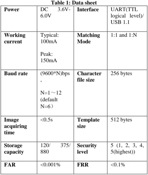
Table 1: Data sheet
Power DC
3.6V-6.0V
Interface UART(TTL logical level)/ USB 1.1 Working
current
Typical: 100mA Peak: 150mA
Matching Mode
1:1 and 1:N
Baud rate (9600*N)bps ,
N=1~12 (default N=6)
Character file size
256 bytes
Image acquiring time
<0.5s Template size
512 bytes
Storage capacity
120/ 375/ 880
Security level
5 (1, 2, 3, 4, 5(highest))
[image:5.595.309.548.472.755.2]Average searching time
< 0.8s (1:880)
Window dimension
18mm*22mm
Working environmen t
Temp: -10℃- +40℃ RH: 40%-85%
Storage environme nt
Temp: -40℃- +85℃
RH: <85%
Outline Dimension
Split type
Integral type
Module: 42*38*7mm Sensor:56*20*21.5mm 54.5*20.6*23.8mm
ContRoller: The controllers AT89S52 and PIC16F87X are available as per tttheir data sheets. [10, 13]
5.
CONCLUSION
This paper aims to explain the various elements that can be integrated to enhance the security framework of an airport and thus boost the efficiency of the airline industry. Further work can be carried out to improve the arrival phase by creating a large database to link the customer details with their finger-prints and the boarding passes this lessens the confusion created while retrieving the baggage from the carousel.
6.
ACKNOWLEDGEMENT
We take this as a chance to extend our gratitude to our External Guide, Mr. Rithick Balaji, B.E., M.Tech., Ph.D., Remotech Engineers Public Ltd., for enlightening us through the PLC training and providing us constant help to complete this project.
7.
REFERENCES
[1] Baggage Traffic Control in Airports making use of RFID Technology, MostafaTavassoli, AbolfazlRajabi, MehrdadJavadi, SasanMohammadi, International Journal of Soft Computing and Engineering (IJSCE) ISSN: 2231-2307, Volume-2, Issue-5, November 2012
[2] The History of RFID Technology. RFID Journalwww.rfidjournal.com/article/articleview/1338/1/1 29/.Alok mishra, Deepti Mishra“ application of RFID in aviationindustry: anexploratory review”, Traffic and Transportation,Vol: 22, 2010, No. 5, 363-372
[3] T.Zhang, Y.Ouyang, Y.He, “Traceable Air Baggage Handling System based on RFID tags in the airport”, Journal of Theoretical and Applied Electronic Commerce Research,Vol 3, April 2008 , 106-115.
[4] JansonHui “RFID in Airports – Baggage and Passenger Tracking”, 188 – Intro to RFID June 8, 2008.
[5] Collins, J. (2004) Delta Plans US-Wide RFID System: the Airline Carrierwill Spend up to $25 Million during the Next Two Years to Roll out anRFID Baggage-Handling System at Every US Airport it Serves. RFIDJournal, 2July, available at www.rfidjournal.com/article/articleview/1013/1/1 [6] SITA (2006) Mishandled Baggage Costs Air Travel
Industry $2.5 Billion a Year. WIRELESS NEWS, 10Meters, http://www.10meters.com
[7] IATA (2008) Fact sheet: Radio Frequency Identification (RFID) for aviation available at: http://www.iata.org/pressroom/
facts_figures/fact_sheets/RFID.html
[8] RFID in AirportManagement, HomiLimbuwala. VP, Business Development, SkandSoft Technologies September 15, 2007, Dataquest, dqindia.com, A cyber Media [email protected] [9] Image processing applications at vienna airport with
basis in baggage handling, excursion exercise in applications of image processing 183.155 supervisor robert sablatnig vienna, january 20, 2009
[10]www.atmel.com [11]www.cytron.com.my
[12]http://www.delta.com.tw/industrialautomation [13]http://www.microchip.com