A Framework for Load Sharing in Clustered Ad Hoc
Networks
Ratish Agarwal
Department of Information Technology, RGPV, Bhopal
Mahesh Motwani
Department of Computer Science, RGPV, Bhopal
Roopam Gupta
Department of Information Technology, RGPV, Bhopal
ABSTRACT
In ad hoc networks, Clustering provides a hierarchical structure in which certain nodes are assigned the extra task (such as routing) of the network. Ordinary nodes do not participate in the routing instead they rely on coordinators of the clusters (clusterheads) for packet delivery. If a suitable tap is not applied on the number of nodes that join a clusterhead as its members, formation of bottleneck can takes place at the overloaded clusterheads. The performance of the network may get affected due to the bottleneck. This paper proposes a cluster formation algorithm in which, if the number of members of a clusterhead exceeds the predefined threshold value, a procedure of cluster division is executed. This relieves the clusterheads from the burden of excessive members. Simulation study of the proposed algorithm justifies the facts by observing an improvement in the performance in terms of E2E delay, PDF and throughput.
Keywords
Mobile ad hoc network, clustering, clusterhead, load, energy
1.
INTRODUCTION
A mobile ad hoc network is a decentralized type of network formed by collection of autonomous mobile nodes connected by wireless links.
Constraints such as limited bandwidth, energy scarcity, mobility, non-deterministic topology and physically insecure environment make ad hoc routing a challenging area of research. In a large ad hoc network, clustering is a solution to limit the amount of routing information that propagates inside the network. In a cluster one node works as a clusterhead and coordinates all the activities such as routing. The selection of the clusterheads is a critical issue, since the performance of the network depends up on the suitability of those nodes as clusterheads.
This research work is carried out to develop a framework for load sharing in resource scares mobile ad hoc networks. The selection of clusterhead is performed by considering a number of performance parameters related to load-balancing, energy consumption and stability of the nodes. The load balancing is achieved by incorporating a threshold value on the number of nodes that can join a clusterhead as its members. If a clusterhead becomes overloaded due to migration of nodes in its vicinity than cluster splitting is performed to form a new cluster. Energy consumption during the communication within a cluster is also taken under consideration at the time of clusterhead selection.
Finally, a simulation of the proposed work is performed on NS2. Comparisons and analysis are made between the
proposed approach and the weighted clustering algorithm to demonstrate the effectiveness of the scheme.
The rest of the paper is organized as follows: Sect. 2 gives a brief note on the state of the art of the research efforts in the area of clustering approaches. The proposed model is briefly introduced in Sect. 3. Sect. 4 analyzes the results of the proposed model using network simulator and final conclusions are given in Sect. 5.
2.
LITERATURE REVIEW
A number of clustering approaches have been presented time to time by renowned authors. In Lowest ID cluster algorithm (LIC) [1] a node with the minimum id is chosen as a clusterhead. Thus, the ids of the neighbors of the clusterhead will be higher than that of the clusterhead. Each node is assigned a distinct id. Periodically, the node broadcasts the list of nodes that it can hear. A node which only hears nodes with id higher than itself is a clusterhead. Otherwise, a node is an ordinary node. Drawback of lowest ID algorithm is that certain nodes are prone to power drainage [2] due to serving as clusterheads for longer periods of time.
In Highest connectivity clustering algorithm (HCC) [1] the degree of a node is computed based on its distance from others. Each node broadcasts its id to the nodes that are within its transmission range. The node with maximum number of neighbors (i.e., maximum degree) is chosen as a clusterhead. This system has a low rate of clusterhead change but the throughput is low. Typically, each cluster is assigned some resources which is shared among the members of that cluster. As the number of nodes in a cluster is increased, the throughput drops. K-CONID [3] combines two clustering algorithms: the Lowest-ID and the Highest-degree heuristics. In order to select clusterheads connectivity is considered as a first criterion and lower ID as a secondary criterion. In HCC clustering scheme, one cluster head can be exhausted when it serves too many mobile hosts. It is not desirable and the CH becomes a bottleneck. So a new approach [4] is given in which when a CH's Hello message shows its dominated nodes' number exceeds a threshold (the maximum number one CH can manage), no new node will participate in this cluster. Adaptive multihop clustering [5] sets upper and lower bounds (U and L) on the number of clustermembers within a cluster that a clusterhead can handle. When the number of clustermembers in a cluster is less than the lower bound, the cluster needs to merge with one of the neighboring clusters. On the contrary, if the number of clustermembers in a cluster is greater than the upper bound, the cluster is divided into two clusters.
hoc network into d-hop clusters based on mobility metric. The objective of forming d-hop clusters is to make the cluster diameter more flexible. Local stability is computed in order to select some nodes as clusterheads. A node may become a clusterhead if it is found to be the most stable node among its neighborhood. Thus, the clusterhead will be the node with the lowest value of local stability among its neighbors. In Mobility Based Metric for Clustering [7] a timer is used to reduce the clusterhead change rate by avoiding re-clustering for incidental contacts of two passing clusterheads. Mobility-based Frame Work for Adaptive Clustering [8] partition a number of mobile nodes into multi-hop clusters based on (a, t) criteria. The (a, t) criteria indicate that every mobile node in a cluster has a path to every other node that will be available over some time period ‘t’ with a probability ‘a’ regardless of the hop distance between them.
Most of protocols executes the clustering procedure periodically, and re-cluster the nodes from time to time in order to satisfy some specific characteristic of clusterheads. In LCC [9] the clustering algorithm is divided into two steps: cluster formation and cluster maintenance. The cluster formation simply follows LIC, i.e. initially mobile nodes with the lowest ID in their neighborhoods are chosen as clusterheads. Re-clustering is event-driven and invoked if two clusterheads move into the reach range of each other and when a mobile node cannot access any clusterhead. Adaptive clustering for mobile wireless network [10] ensures small communication overhead for building clusters because each mobile node broadcasts only one message for the cluster construction.
3-hop between adjacent clusterheads (3-hBAC) [11] algorithm introduce a new node status, “clusterguest”, which means this node is not within the transmission range of any clusterheads, but within the transmission range of some clustermembers. When a mobile node finds out that it cannot serve as a clusterhead or join a cluster as a clustermember, but some neighbor is a clustermember of some cluster, it joins the corresponding cluster as a clusterguest.
A clustering protocol that does not use dedicated control packets or signals for clustering specific decision is Passive Clustering [12]. In this scheme, when a potential clusterhead with “initial” state has something to send, such as a flood search, it declares itself as a clusterhead by piggybacking its state in the packet. Load balancing clustering (LBC) [13] provide a nearby balance of load on the elected clusterheads. Once a node is elected a clusterhead it is desirable for it to stay as a clusterhead up to some maximum specified amount of time, or budget. Initially, mobile nodes with the highest IDs in their local area win the clusterhead role. LBC limits the maximum time units that a node can serve as a clusterhead continuously, so when a clusterhead exhausts its duration budget, it resets its VID to 0 and becomes a non-clusterhead node. Power-aware connected dominant set [14] is an energy-efficient clustering scheme which decreases the size of a dominating set (DS) without impairing its function. The unnecessary mobile nodes are excluded from the dominating set saving their energy consumed for serving as clusterheads. Mobile nodes inside a DS consume more battery energy than those outside a DS because mobile nodes inside the DS bear extra tasks, including routing information update and data packet relay. Hence, it is necessary to minimize the energy consumption of a DS. Clustering for energy conservation [15] assumes two node types: master and slave. The purpose of of this scheme is to minimize the transmission energy consumption summed by all master-slave pairs and to serve as
many slaves as possible in order to operate the network with longer lifetime and better performance.
Weighted clustering algorithm (WCA) [16] selects a clusterhead according to the number of nodes it can handle, mobility, transmission power and battery power. To avoid communications overhead, this algorithm is not periodic and the clusterhead election procedure is only invoked based on node mobility and when the current dominant set is incapable to cover all the nodes. The clusterhead election algorithm finishes once all the nodes become either a clusterhead or a member of a clusterhead. The distance between members of a clusterhead, must be less or equal to the transmission range between them. No two clusterheads can be immediate neighbors. In WCA high mobility of nodes leads to high frequency of reaffiliation which increase the network overhead. Higher reaffiliation frequency leads to more recalculations of the cluster assignment resulting in increase in communication overhead. Entropy based clustering [17] overcomes the drawback of WCA and forms a more stable network. It uses an entropy-based model for evaluating the route stability in ad hoc networks and electing clusterhead. Entropy presents uncertainty and is a measure of the disorder in a system. So it is a better indicator of the stability and mobility of the ad hoc network. The clustering approach presented in WBACA [18] is based on the availability of position information via a Global Positioning System (GPS). The WBACA considers following parameters of a node for clusterhead selection: transmission power, transmission rate, mobility, battery power and degree. In Connectivity, energy & mobility driven weighted clustering algorithm (CEMCA) [19] the election of the cluster head is based on the combination of several significant metrics such as: the lowest node mobility, the highest node degree, the highest battery energy and the best transmission range.
3.
PROPOSED METHODOLOGY
3.1 Clustering framework
Clustering naturally facilitates an energy efficient technique where nodes forwards to a cluster head for processing. Selection of clusterhead is one of the major issues in design of mobile ad hoc networks. The selection of clusterhead is performed after considering a number of performance parameters including degree difference, distance with neighbors, mobility of nodes and remaining battery power.
3.1.1 Degree difference
In cluster-based structure a performance parameter for load balancing can be introduced as degree difference (Δv)), for each node v which is defined as the difference of ideal node degree (δ) and actual degree (connectivity) of that node. Degree of node (dv) is the number of neighbors of node v that are in the transmission range. Ideal degree is the number of neighbors that a clusterhead can handle effectively.
Degree difference (Δv) = | dv- δ |
Δ δ δ
Lower value of degree difference would be advantageous for achieving good load balancing.
3.1.2 Energy Consumption
In mobile ad hoc network nodes communicate with each other through the wireless channel, the Friis transmission equation is as follows
Or,
Where, Pt is transmitted power and Pr is power at the receiving antenna, Gt and Gr are the antenna gains, is the wavelength used and R is the distance between the nodes. Energy-consumption of a node is directly proportional to the distance of that node with its neighbors.
Sum of distance to all neighbors (Sdv) is found as
Where (xv, yv) and (xk, yk) are the coordinates of the node v
and node k respectively. Summation is done for all neighbors k of node v.
3.1.3 Mobility
Mobility or stability is an important factor in deciding the clusterheads. In order to avoid frequent clusterhead changes, it is desirable to elect a clusterhead that does not move very quickly. When the clusterhead moves fast, the nodes may be detached from the clusterhead and as a result, a reaffiliation occurs. Reaffiliation can increase computation and processing, which is not a desirable feature. The running average of the speed for every node till current time T gives a measure of mobility and is denoted by Mv, as
Where (xt, yt ) and (xt−1, yt−1) are the coordinates of the node v
at time t and (t − 1), respectively.
3.1.4 Power
A clusterhead consumes more battery than an ordinary node because it has extra responsibilities. We can estimate the remaining battery power by the amount of time spent by the node as a clusterhead. The parameter Pv is the cumulative time of a node being a clusterhead. Pv is used to measure how much battery power has been consumed by the node. Higher the value of Pv lower the remaining battery power.
All four parameters (Δv ,Sdv, Mv ,and Pv, ) explained above can
be used as a performance matrix for selection of a node as a clusterhead. Weight of these parameters can change according to requirement. Weighing factors are chosen in such a way that sum of these factors must be equal to one. Suppose we have chosen W1, W2, W3, and W4 as weighing factors for four
performance parameters given above then
Combined weight of a node Wvcan be calculated as follows
Each node calculates its weight and broadcasts it periodically in a hello packet to all nodes in its transmission range. When a node receives the weights of its 1-hop neighbors, it inserts them in the possible CH set, which includes all potential cluster-heads.
3.2
Cluster formation with load sharing
At the system initiation each node assumed to be holding astatus “undecided”. Periodic broadcast of hello message enables a node to gather useful information about its neighborhood. Based upon the information obtained from the hello messages each node computes the combined weight value. This information is further exchanged by neighbors and nodes store this neighborhood information including combined weight in neighbor tables. If a node determines that it has the lowest value of combined weight among its neighbors, it changes its status as “CH” and sends “join_cluster” messages to its neighbors. Each neighboring node receiving this join request check its own status and if it is still “undecided” , it respond with “accept_join” and become a member of that clusterhead and change its status as “member”. This process runs in parallel and continued until all the nodes of the network either become clusterheads or members.
In ad hoc networks nodes are free to move within the clusters, and of course move in and out of a cluster. If member nodes move from one cluster to another than they can resign from
Algorithm 1: Cluster formation algorithm
1. Calculate the combined weight Wv of each node v
2. Broadcast Wv to all immediate neighbors
3. Process the broadcast received from immediate neighbors and record the Wx
4. If {Wv < Wx}
5. Node v select itself as clusterhead Start a timer Tclusterhead
Send “join_cluster” message to all nodes x in the neighbor table 6. If { Node x is neither a CH nor a
Member of any cluster} 7. Node x accept “Join_cluster”,
reply with “accept_join” to v else
8. does not respond to join request else
9. node v is not a CH, wait for join_cluster from other CH
10. Go to step 4 if there is any node with status “undecided”
B
C A
E
F G
D
H
P
Q
S R
C1
C2
C3
[image:4.595.54.284.70.302.2]
Fig. 1: Cluster division
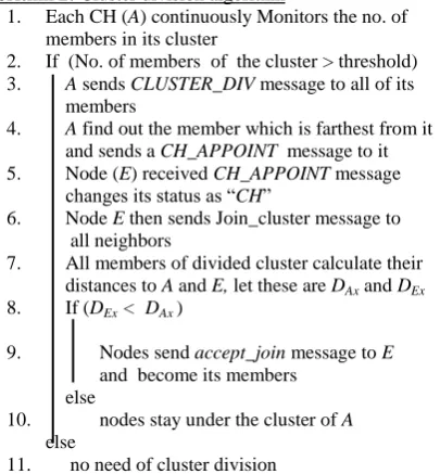
This work addresses this issue by splitting the cluster in two parts. Figure 1 show two clusters C1 and C2, nodes A and Q are the clusterheads of these clusters respectively. Clusterhead A has seven members which is greater than threshold and thus A is overloaded and cluster division is needed. The clusterhead of the parent cluster (node A) can appoint another member node as the clusterhead of the second (disjointed) cluster C3. The selection of the new clusterhead is based on its distance from the current clusterhead. The node which is farthest from the current clusterhead is appointed as new clusterhead (node E in this case). Consideration of distance at the time of clusterhead appointment helps to reduce the extra power consumed in communication with large distant nodes. All the members of the parent cluster find out distance to newly appointed clusterhead. Nodes join the new cluster if the newly appointed clusterhead is closer as compared to parent clusterhead. Otherwise they stay under the affiliation of parent cluster.
Algorithm 2: Cluster division algorithm
1. Each CH (A) continuously Monitors the no. of members in its cluster
2. If (No. of members of the cluster > threshold) 3. A sends CLUSTER_DIV message to all of its
members
4. A find out the member which is farthest from it and sends a CH_APPOINT message to it 5. Node (E) received CH_APPOINT message
changes its status as “CH”
6. Node E then sends Join_cluster message to all neighbors
7. All members of divided cluster calculate their distances to A and E, let these are DAx and DEx
8. If (DEx < DAx)
9. Nodes send accept_join message to E and become its members
else
10. nodes stay under the cluster of A else
11. no need of cluster division
3.3
Data structures used in EPT-WBC
algorithm
3.3.1 Hello message
Neighborhood information may be determined through the reception of broadcast control messages [20]. Any broadcast control message also known as a hello message, indicating the presence of a neighbor. When a node receives a hello message from its neighbor, it creates or refreshes of the neighbor table. Time interval between two successive hello messages is called “hello_interval”. Adjustment of hello_interval is a critical issue and depends up on the mobility patterns of nodes. If nodes are highly mobile, the hello_interval must be kept small to maintain consistent and accurate topology information of the network. On the other hand if nodes are less mobile, the hello_interval may be prolonged to relax the network from excessive overhead due to hello messages.
Another important variable “allowed_hello_loss” is defined as the maximum number of periods of hello_interval to wait without receiving a hello message before detecting a loss of connectivity to that neighbor. The recommended value of hello_interval is one second and allowed_hello_loss is two. Hello packet of a node A is shown in figure 2 and it includes the following information:
Two bit field “S” that represents the Status of A, This value can be 0 for Undecided, 1 for Cluster Head or 2 for Cluster Member.
Four bytes field to represent the ID of node A, commonly 32 bit IP address of node is used as ID.
Four byte field to specify position coordinates of node A. Two bytes field for weight value of node A.
One bytes field to represent number of 1-hop neighbors. One bytes field for number of adjacent clusterheads. Four bytes field to specify the status of 1-hop neighbors
of node A. The status of each one of A’s neighbor is represented by two bits. This four byte field can accommodate status of 16 neighbors. This block is repeated after the details of 16 neighbors. In the case that there are no more than 16 neighbors listed, there will be only one such neighbor status block.
Four byte fields for ID of each one of 1-hop neighbors of node A obtained from neighbor table.
S
S1 S2 S3 S4 S5 S6 S7 S8 S9 S10 S11 S12 S13 S14 S15 S16 NODE ID
X-Coordinate Y-Coordinate
0 1 2 3
ID of neighbor-4
weight value I-hop neighbors adjacent CH
ID of neighbor-3 ID of neighbor-1 ID of neighbor-2
ID of neighbor-5
Fig. 2: Hello message of node A
3.3.2 Neighbor table
Each node of the network maintains a neighbor table to keep the record of each one of its neighbors. This information is used for cluster formation and route discovery. Each entry of the neighbor table contains information about one of its one B
C A
E
F G
D
H
P
Q
S R
C1
[image:4.595.69.272.530.749.2]hop neighbors. Neighbor information may include its ID, position, status (i.e. clusterhead, member or undecided as shown in table 1. Neighbor table also contains combined weight of node received in the last hello message and a timer (Tneighbor) used to clear the table entry if it does not hear from
the neighbor in a predefined time interval.
Table 1: Neighbor table of node B
ID of neighbor
X position
Y position
Status Weight Timer
Neighbors table is updated upon receiving a hello message from its neighbor; suppose a node B received a hello message from its neighbor A than node B modifies its own Neighbor Table as follows:
Node B checks its neighbor table to find out that it has an entry for node A. If it does not has any entry, adds a new entry for node A as its one hop neighbor and fills all the fields by copying from hello packet of node A.
If node A is already in B’s Neighbor Table, B updates the entries for node A and reset the timer. Each entry in the neighbor table is associated with a timer (Tneighbor). A table
entry will be removed if a hello message from the entry’s node is not received for a period of (allowed_hello_loss + 1) * hello_interval. For a stable topology the neighbor table of a node will have complete information of the neighborhood.
Cluster adjacency table
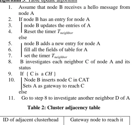
Each node B also maintains a cluster adjacency table (CAT). The CAT table records the ID of each neighboring clusterhead and a gateway node to reach that clusterhead (table 2). This table is updated on receiving hello message from its neighbors A. Status of each neighbor C of node A is examined to find out nodes with status “clusterhead”, if node C is clusterhead, it is entered as adjacent clusterhead in CAT with node A as gateway to reach it. This table is used during route discovery and data forwarding.
Algorithm 3: Table update algorithm
1. Assume that node B receives a hello message from node A
2. If node B has an entry for node A 3. node B updates the entries of A 4. Reset the timer Tneighbor
else
5. node B adds a new entry for node A 6. fill all the fields of table for A 7. set the timer Tneighbor
8. B investigates each neighbor C of node A and its status
9. If { C is a CH }
10. Node B inserts node C in CAT Sets A as gateway to reach C
else
[image:5.595.321.537.254.399.2]11. Go to step 8 to investigate another neighbor D of A
Table 2: Cluster adjacency table
ID of adjacent clusterhead Gateway node to reach it
4.
SIMULATION AND RESULT
ANALYSIS
Proposed work has been simulated on ns2 simulator and the performance of the work can be compared with that of WCA and the factors considered are PDR, throughput, E2E delay and load balancing.
4.1 Packet Delivery Fraction (PDF)
Packet delivery ratio is defined as the ratio of total packets transmitted to total packets received at the destination. In WCA some of the packets may drop due to congestion and buffer overflow at the clusterheads, this results in the drop of PDF whereas in the proposed work we have performed load balancing and this improves PDF (figure 3).
Fig. 3 PDF with packet interval
4.2 Throughput
[image:5.595.58.283.493.707.2]Throughput measures the effective utilization of the channel and is measured in kbps. The result shown in figure 4 show that the proposed work shows better throughput than the WCA. In WCA, packets have to wait for their turn because some of the clusterheads may be overloaded and congested. Proposed work uniformly distributes the load on the selected clusterheads and thus good throughput is maintained.
Fig. 4: Throughput with packet interval
4.3 E2E Delay
This metric includes all possible delay that may be caused by: buffering during route discovery, queuing at the interface queue, retransmission delay at the MAC layer, propagation and transfer time. It is defined as the time taken for a data
60 65 70 75 80 85 90
1 0.2 0.1 0.066
P
D
F
Packet interval in seconds PDF Vs Packet Interval
LSC
WCA
0 50 100 150 200 250 300 350
1 0.2 0.1 0.066
T
h
ro
u
g
h
p
u
t
in
k
b
p
s
Packet interval in seconds Throughput Vs Packet interval
LSC
[image:5.595.319.534.536.676.2]packet to be transmitted across a MANET from source to destination. The E2E metric is given by:
E 2 E delay = Tr − Ts
[image:6.595.318.538.74.213.2]Where, Tr is the time that a packet is received and Ts the time that this packet was injected into the network.
Fig. 5: E2E delay with poacket interval
As the traffic in the network increases, the clusterheads have to bear the increased load of routing the packets form source to destination. If clusterheads are serving a large no. of members than, there is a change that some of the clusterheads may become bottleneck due to congestion, this results larger end to end delay of routed packets. Controlling the number of members of a clusterhead, results in improved performance at the time of routing in heavy traffic conditions. WCA does not limit the member of a clusterhead and thus, as the packet interval is decreased, more packets are transmitted by the source nodes in the unit time and this results in the more e2e delay. In proposed work a threshold is set on no. of members, so clusterheads are not overloaded. The e2e delay in the proposed algorithm is less than that of WCA as shown by experimental results shown in figure 5.
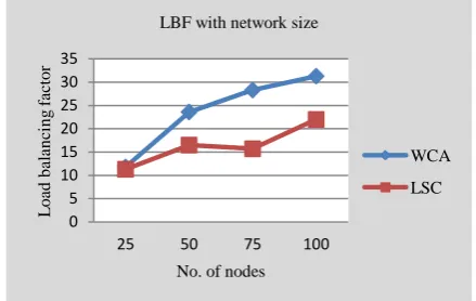
4.4. Load Balancing
Load balancing factor (LBF) can be used to measure how well balanced the clusterheads are. For a network with N number of nodes, cluster-based structure is formed by k number of clusters and each cluster has xk number of members.
Average of the number of neighbors of each clusterhead is μ and
μ = (N-k) / k Load balancing factor is defined as
Lower the value of load-balancing factor better the cluster algorithm is, because the difference between the average number of members and the actual number of members in each cluster would be minimized.
Fig. 6: Load balancing factor with network size
WCA does not have any limit on the number of members of clusterheads and thus there is non-uniform distribution of the load on the clusterheads. Proposed work distributes the load uniformly and an improved load balancing factor is achieved as shown in figure 6.
5.
CONCLUSIONS
In conclusion this work provides a framework for load sharing in crowded clusters. Though clustering provides a good technique to reduce the control overhead in scalable ad hoc networks but there is always a chance of formation of bottleneck at the clusterheads. The bottleneck can degrade the performance of the network. Proposed LSC subdivide the overloaded cluster in two clusters and the head of the new born cluster is chosen by considering the power consumption during communication and weight values of the nodes. Since more power is needed to communicate at large distance, the farthest away node with suitable weight is assigned as the new clusterhead. Members that are nearer to new clusterhead as compared to old clusterhead, join new clusterhead as its members. Uniform distribution of the load on the selected clusterheads can improve the performance in terms of PDF, throughput, E2E delay and Load balancing.
REFERENCES
[1] M. Gerla and J. T. Tsai, “Multiuser, Mobile, Multimedia RadioNetwork” Wireless Networks, 1995, vol. 1, pp. 255–65.
[2] A.D. Amis, R. Prakash, T.H.P Vuong, D.T. Huynh. "Max-Min D-Cluster Formation in Wireless Ad Hoc Networks" In proceedings of IEEE Conference on Computer Communications (INFOCOM) 2000, Vol. 1. pp. 32-41. [3] G. Chen, F. Nocetti, J. Gonzalez, and I. Stojmenovic,
“Connectivity based k-hop clustering in wireless networks” proceedings of the 35th Annual Hawaii International Conference on System Sciences, 2002, Vol. 7, pp. 188.3.
[4] F. Li, S. Zhang, X. Wang, X. Xue, H. Shen, “Vote- Based Clustering Algorithm in Mobile Ad Hoc Networks”, In proceedings of International Conference on Networking Technologies, 2004.
[5] T. Ohta, S. Inoue, and Y. Kakuda, “An Adaptive Multihop Clustering Scheme for Highly Mobile Ad Hoc Networks,” in proceedings of 6th ISADS, 2003.
[6] I. Er and W. Seah. “Mobility-based d-hop clustering algorithm for mobile ad hoc networks” IEEE Wireless Communications and Networking Conference, 2004, Vol. 4, pp. 2359-2364.
0 100 200 300 400 500 600 700 800
1 0.2 0.1 0.066
E2
E
d
el
ay
i
n
m
s
Packet interval in seconds E2E dalay Vs Packet interval
LSC
WCA
0 5 10 15 20 25 30 35
25 50 75 100
L
o
ad
b
al
an
ci
n
g
f
ac
to
r
No. of nodes LBF with network size
WCA
[image:6.595.58.276.137.273.2][7] P. Basu, N. Khan, and T. D. C. Little, “A Mobility Based Metric for Clustering in Mobile Ad Hoc Networks” in proceedings of IEEE ICDCSW’ 2001, pp. 413–18.
[8] A. B. MaDonald and T. F. Znati, “A Mobility-based Frame Work for Adaptive Clustering in Wireless Ad Hoc Networks” IEEE JSAC, 1999, vol. 17, pp. 1466–87.
[9] C.-C. Chiang, “Routing in Clustered Multihop, Mobile Wireless Networks with Fading Channel” in proceedings of IEEE SICON’1997.
[10] C. R. Lin and M. Gerla, “Adaptive Clustering for Mobile Wireless Networks” IEEE JSAC, vol. 15, pp. 1265–75. [11] J. Y. Yu and P. H. J. Chong, “3hBAC (3-hop between
Adjacent Clusterheads): a Novel Non-overlapping Clustering Algorithm for Mobile Ad Hoc Networks” in proceedings of IEEE Pacrim’2003, vol. 1, pp. 318–21.
[12] T. J. Kwon et al., “Efficient Flooding with Passive Clustering an Overhead-Free Selective Forward Mechanism for Ad Hoc/Sensor Networks” in proceedings of IEEE, 2003, vol. 91, no. 8, pp. 1210–20. [13] A. D. Amis and R. Prakash, “Load-Balancing Clusters in
Wireless Ad Hoc Networks” in proceedings of 3rd IEEE ASSET’2000, pp. 25–32.
[14] J. Wu et al., “On Calculating Power-Aware Connected Dominating Sets for Efficient Routing in Ad Hoc
Wireless Networks” J. Commun. and Networks, 2002, vol. 4, no. 1, pp. 59–70.
[15] J.-H. Ryu, S. Song, and D.-H. Cho, “New Clustering Schemes for Energy Conservation in Two-Tiered Mobile Ad-Hoc Networks,” in proceedings of IEEE ICC’2001, vo1. 3, pp. 862–66.
[16] M. Chatterjee, S. Das, and D. Turgut. WCA: A weighted clustering algorithm for mobile ad hoc networks, Cluster computing Journal, 2002, vol. 5(2), pp. 193–204. [17] Yu-Xuan Wang, Forrest Sheng Bao, "An Entropy-Based
Weighted Clustering Algorithm and Its Optimization for Ad Hoc Networks" Third IEEE International Conference on Wireless and Mobile Computing, Networking and Communications, 2007.
[18] S.K. Dhurandher and G.V. Singh” Weight-based adaptive clustering in wireless ad hoc networks” IEEE, 2005.
[19] F.D.Tolba, D. Magoni and P. Lorenz “ Connectivity, energy & mobility driven Weighted clustering algorithm ” in proceedings of IEEE GLOBECOM, 2007.