Chaotic Adaptive Control of Non-Binary
TTCM Decoding Algorithm
Riyadh A. Al-hilali
Iraqi affiliation College of Engineering Al-Mustansiriyah UniversityAbdulkareem S. Abdallah
Iraqi affiliationCollege of Engineering Basrah University
Raad H. Thaher
Iraqi affiliation College of Engineering Al-Mustansiriyah UniversityABSTRACT
This paper presents a non-binary Turbo Trellis Coded Modulation (TTCM) decoder-based multidimensional 3-D (Maximum A Posteriori) MAP algorithm. The proposed system deals with Non-binary error control coding of the TTCM scheme for transmissions over the AWGN channel. The idea of Non-binary codes has been extended for symbols defined over rings of integers, which outperform binary codes with only a small increase in decoding complexity. This paper employs chaos technique at the decoding stage of the Non-binary TTCM decoder, since the turbo decoding algorithm can be viewed as a high-dimensional dynamical nonlinear system. A simple technique to control transient chaos of turbo decoding algorithm is devised. The analysis of non-linear discrete deterministic Non-binary TTCM decoder used the Binary (0-1) test for chaos to distinguish between regular and chaotic dynamics. The most powerful aspect of the method is that it is independent of the nature of the vector field (or data) under consideration. The simulation results show that the performance of the non-binary TTCM decoding algorithm-based chaos technique outperforms the binary and non-binary decoding methods.
General Terms
Non-binary error correcting codes, Groups, Rings of integers, MAP algorithm, chaos communications.
Keywords
Turbo codes, TTCM, chaos techniques, nonlinear phenomena of dynamic systems.
1.
INTRODUCTION
The design of signal processing algorithms for digital data seems much easier than designing analog signal processing algorithms. The abundance of such digital algorithms, including error control and correction techniques, combined with their ease of implementation in very large-scale integrated (VLSI) circuits, has led to many successful applications of error control coding in practice.
Advances in coding, such as turbo [1] and low density parity check codes [2], made it feasible to approach the Shannon capacity limit [3] in systems with a single antenna link. Significant further advances in spectral efficiency are
available through increasing the number of antennas at both the transmitter and the receiver [4, 5, 6].
Further performance gains can be achieved by using non-binary codes in the coded modulation scheme, but with an increase in the decoding complexity [7]. Non-binary codes are the most commonly used error-correcting codes and can be found in optical and magnetic storage, high-speed modems and wireless communications. Most digital communication today is carried out using electronic devices that are essentially “linear”, and linear system theory has been used to continually refine their performance. In many cases, inherently nonlinear devices are linearized in order to achieve a certain level of linear system performance.
The potential advantages of operation of nonlinear devices for generation of digital communication signals include improved efficiency, lower dc power, lower probability of intercept, and lower probability of detection.
Nonlinear techniques can also be potentially applied to channel encoding/decoding functions, where there may be some benefit to chaotic channel coding techniques for greater immunity to channel fading problems [8]. The turbo decoding algorithm is a high-dimensional dynamical system parameterized by a large number of parameters (for a practical realization the turbo decoding algorithm has more than 103 variables and is parameterized by more than103 parameters). In this thesis, the turbo decoding algorithm is treated as a dynamical system parameterized by a single parameter that closely approximates the signal-to-noise ratio (SNR). A whole range of phenomena known to occur in non-linear systems, such as the existence of multiple fixed points, oscillatory behavior, bifurcations, chaos, and transient chaos are found in the turbo decoding algorithm.
N. Mobini, 2011 [9] proposed a new iterative decoding algorithm for Low-Density Parity-Check (LDPC) codes and used the adaptive scaling factor α𝑒−𝛽 to speed up the convergence of the LDPC decoding codes. But there might be other non-linear scaling functions that can perform better. A further search for discovering other alternative scaling functions makes an interesting research topic.
popular, it would expect non-binary turbo codes to perform just as well and this would be an interesting area of research for the future.
2.
BINARY TURBO CODES
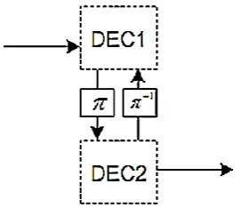
[image:2.595.96.232.304.421.2]One of the most important breakthroughs in coding theory was the development of turbo codes. According to Shannon, the ultimate code would be one where a message is sent infinite times, each time shuffled randomly. The receiver has infinite versions of the message albeit corrupted randomly. From these copies, the decoder would be able to decode with near error-free probability the message sent. This is the theory of an ultimate code, the one that can correct all errors for a virtually signal. Turbo code is a step in that direction. Turbo codes are a parallel concatenation of recursive systematic convolutional (RSC) encoders separated by an interleaver [11]. Turbo codes provide a practical way of achieving near-Shannon limit performance by using an iterative decoder that contains two soft-input–soft-output component decoders in series, passing reliability information between them, (see Figure 1).
Fig 1: Iterative decoding in MAP algorithm
2.1
Non-Binary Iterative Turbo Decoding
Turbo codes are decoded using a method called the Maximum Likelihood Detection or MLD. Filtered signal is fed to the decoders, and the decoders work on the signal amplitude to output a soft “decision”. The form of MLD decoding used by turbo codes is called the Maximum a-posteriori Probability or MAP. The MAP algorithm is used iteratively to improve performance.The idea of the non-binary turbo decoding process is the same idea of the binary turbo decoding process, in which the extraction of extrinsic information from the output of one decoder and pass it on to the second decoder in order to improve the reliability of the second decoder‟s output and vice versa. But, the differences between two decoders aren't in the idea but in mechanisms of decoder parameters design and the decision type as in the following situations:
The de-mapping procedure of modulated signal into a set ring of integersℤ𝑀.
Calculation the reliabilities of information bits, parity bits, and interleaved parity bits must be in a ring of integersℤ𝑀.
Decision method that would be made on the log-likelihood ratios, since the symbols to be decided are defined over a ring of integers ℤ𝑀(i.e., 0, 1, 2, . . . M – 1) and not defined over a binary numbers (i.e., 0 and 1).
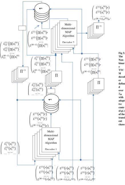
A general block diagram of the non-binary turbo decoder is (shown in Figure 2).
Where;
𝑟𝑡(0) is the received information bit.
𝑟𝑡(1)is the received parity bit from the first RSC encoder.
𝑟𝑡(2)is the received information bit from the second RSC encoder.
These notations can be defined in more details below:
𝑟𝑡(𝑖)= 𝑎𝑡(𝑖)+ 𝜂𝑡, 𝑖 = 0,1,2. (1)
Where 𝑎𝑡(𝑖)ℝ, i = 0, 1, 2 is the mapping of 𝑉𝑡(𝑖) to an M–ary modulation scheme constellation and ℝ is a set of real numbers, since 𝑉𝑡(𝑖)∈ {0, 1, 2, . . . M-1}, are outputs of the non-binary turbo encoder defined previously and, 𝜂𝑡, is an additive white Gaussian noise sample at time t.
To calculate the reliability of the systematic information bit,
𝑟𝑡(0):
𝐿(1) 𝑟
𝑡(0) 𝑎𝑡(0) = 𝑙𝑛
𝑝 𝑟𝑡(0) 𝑎𝑡(0)=−1
𝑝 𝑟𝑡(0) 𝑎𝑡(0)=−3 (2)
Since, 𝑝 𝑟𝑡(0) 𝑎𝑡(0) represents the conditional probability density function (PDF) for AWGN channel and is given by
𝑝 𝑟𝑡 𝑎𝑡 = (1 𝜎 2𝜋) (𝑒
−(𝑟𝑡−𝑎𝑡)2 2𝜎2)
(1 𝜎 2𝜋) 𝑖=±1,±3 (𝑒−(𝑟𝑡−𝑖𝑎𝑡)2 2𝜎2) (3)
Where 𝜎2, represents the noise variance, for 4-PAM modulation with constellation points at ± 𝐸𝑠 , ± 3 𝐸5 𝑠 5 :
𝑝 𝑟𝑡(0) 𝑎𝑡(0)= −1 = (1 𝜎 2𝜋) (𝑒−(𝑟𝑡 0 + 𝐸𝑠 5 )2 2𝜎2)
(1 𝜎 2𝜋) 𝑖=±1,±3 (𝑒−(𝑟𝑡 0 +𝑖 𝐸𝑠 5 )2 2𝜎2) ,
and
𝑝 𝑟𝑡(0) 𝑎𝑡(0)= −3 = (1 𝜎 2𝜋)
(𝑒−(𝑟𝑡 0 +3 𝐸𝑠 5 )2 2𝜎2)
(1 𝜎 2𝜋) 𝑖=±1,±3 (𝑒−(𝑟𝑡 0 +𝑖 𝐸𝑠 5 )2 2𝜎2) ,
then
𝐿(1) 𝑟
𝑡(0) 𝑎𝑡(0) = 𝑙𝑛 𝑒
− 𝑟𝑡 0 + 𝐸𝑠 5 2+(𝑟𝑡 0 +3 𝐸𝑠 5 )2
2𝜎2 , Let
2𝜎2= 𝑁 𝑜
𝐿(1) 𝑟
𝑡(0) 𝑎𝑡(0) = (4 5) 𝐸𝑠 𝑟𝑁𝑜 𝑡(0)+ (8 5) 𝐸𝑠 𝑁𝑜 (4)
Thus, each one of the systematic information bit, 𝑟𝑡(0), the
parity bit from encoder 1,𝑟𝑡(1), and the interleaved parity bit from encoder 2,𝑟𝑡(2), has three reliability values, respectively, as shown below in system of equations:
𝐿(𝑖) 𝑟𝑡(0) 𝑎𝑡(0) = (4 5) 𝐸𝑠 𝑟𝑁𝑜 𝑡 0 + (8 5) 𝐸𝑠 𝑁𝑜 ,
𝐿(𝑖) 𝑟𝑡(1) 𝑎𝑡(1) = (12 5) 𝐸𝑠 𝑟𝑁𝑜 𝑡 1 , (5)
𝐿(𝑖) 𝑟 𝑡
(2)
𝑎𝑡(2) = (8 5) 𝐸𝑠 𝑟𝑁𝑜 𝑡 (2)
+ (8 5) 𝐸𝑠 .𝑁𝑜
3.
NONLINEAR DYNEMICAL
SYSYTEMS
A differentiable discrete-time dynamical system is described by an evolution equation of the form
𝑥𝑛+1= 𝑓(𝑥𝑛) (6)
Where f is a differentiable function and the variables x vary over a state-space M, which can be IRm or a compact manifold. Computer experiments with iterative decoding algorithms usually exhibit transient behavior followed by what appears to be an asymptotic regime.
A subset A of M is said to be invariant if f (A) = A, a compact invariant set A ⊂ M is topologically transitive if there exists x
∈ A such that ω(x) = A, where ω(x) is the set of limit points of the orbit f n(x)n ≥ 0.
3.1
The Turbo Decoding Algorithm as a
Dynamical System
The turbo decoder consists of two components; a decoder D1
for the convolutional code C1 and a decoder D2 for the code
C2. These decoders use the BCJR [12] algorithm to compute
the a posteriori probabilities of the information bits. The posterior likelihood ratio of the ith information bit is given by
𝑝 𝑏 𝑖 ,𝑐 1 𝑏∈ℋ𝑖
𝑝 𝑏 𝑖 ,𝑐 1 𝑏∈ℋ𝑖𝑐 =
𝑝 𝑖 𝑏 𝑝 𝑐 𝑏 𝑞1 2 𝑏 𝑏∈ℋ𝑖
𝑝 𝑖 𝑏 𝑝 𝑐 𝑏 𝑞1 2 𝑏
𝑏∈ℋ𝑖𝑐 (7)
Where 𝑖, 𝑐 ,1 and 𝑐2 be the channel outputs corresponding to the input sequences i, c1, and c2, respectively, while, p(b|𝑖, 𝑐1),
is the posterior probability density, where b ∈ H, and H be the set of all ordered binary strings of length n.
Assuming that p0, p1, and p2 be the normalized densities
equivalent to p(𝑖 |𝑏), 𝑝(𝑐 1|𝑏), and 𝑝(𝑐 2|𝑏), respectively. The likelihood ratios of the information bits according to q1 equal
their extrinsic information and are given by
𝑞1 𝑏𝑖
𝑞1 𝑏0 =
𝑝 𝑏 𝑖 ,𝑐 1 𝑝 𝑏0 𝑖 𝑞2 𝑏0 𝑏∈ℋ𝑖
𝑝 𝑏 𝑖 ,𝑐 1 𝑝 𝑏𝑖 𝑖 𝑞2 𝑏𝑖
𝑏∈ℋ𝑖𝑐 (8)
In the logarithmic domain, equation (6) can be rewritten as
𝑄1 𝑏𝑖 = 𝜋𝑝1 𝑃0+ 𝑄2 𝑏𝑖 − 𝑃0+ 𝑄2 𝑏𝑖 (9)
For i =1,...,n. Recalling that q1 and q2 are initialized to induce
the uniform probability distribution on H. Therefore;𝑄1(𝑙+1)=
𝜋𝑝1 𝑃0+ 𝑄2𝑙 − 𝑃0+ 𝑄2 (10)
The second decoder D2 performs a similar operation and computes the modified prior log-density Q2: 𝑄1
(𝑙)
= 𝜋𝑝2 𝑃0+ 𝑄2𝑙 − 𝑃0+ 𝑄1𝑙 (11)
The decoding algorithm iteratively performs the operations indicated by (9) and (10). The equations (9) and (10) may be considered as a discrete-time dynamical system. Consequently, the turbo decoding algorithm is parameterized by 3n parameters. Hence, in the above formulation, the turbo decoding algorithm is an n-dimensional dynamical system depending on 3n parameters. From the bifurcation analysis in
ℤ
𝑀-ring
MAP
Decode
r 1
ℤ
𝑀-ring
MAP
Decode
r 2
[13], it can be seen that the turbo-decoding algorithm exhibits chaotic behavior for a relatively large range of SNR values.
3.2
The Binary (0-1) Test for Chaos
Recently a new test for determining chaos is introduced Gottwald and Melbourne [14]. In contrast to usual method of computing maximal lyapunov exponent, their method is applied directly to the time series data and does not require phase-space reconstruction. Moreover, the dimension and origin of the dynamical system and the form of the underlying equations are irrelevant. The input is the time series data and the output is 0 or 1, depending on whether the dynamics is non-chaotic or chaotic.3.2.1
Description of the Binary (0-1) Test for
Chaos [15]
Assuming scalar observable φ(j), j = 1, 2, 3, . . . , T a discrete set of measurement data. To test φ(j), the following sequence steps is Performed:
I. for c∈ (π , o), compute the translation variables
𝑝𝑐 𝑡 = 𝑡𝑗 =1∅ 𝑗 cos 𝑗𝑐 , 𝑞𝑐 𝑡 = 𝑡𝑗 =1∅ 𝑗 sin 𝑗𝑐 (12)
for t =1, 2, . . . . T
Claim that
pc(t) is bounded if the underlying dynamics is
non-chaotic (e.g periodic or quasi periodic).
qc(t) behaves asymptotically like Brownian motion
if the underlying dynamics is chaotic .
II. The mean square displacement of the translation variables pc(t) and qc(t) defined in (1), for several values of c
∈ (π , o) . The mean square displacement is defined by
𝑀𝑐 𝑡 = lim𝑛→∞𝑇1 𝑇𝑗 =1 𝑃𝑐 𝑗 + 𝑡 − 𝑃𝑐 𝑗 2+ 𝑞𝑐 𝑗 + 𝑡 −
𝑞𝑐 𝑗 2
(13) and smoothing mean square displacement is
𝑀𝑐 𝑡 𝑛𝑒𝑤 = 𝑀𝑐 𝑡 𝑜𝑙𝑑−1−cos 𝑡𝑐 1−sin 𝑡𝑐 lim𝑇→∞1𝑇 𝑇𝑗 =1𝜑(𝑗) 2
(14)
Such that t << T, t ≤ tcut, where tcut < T. In practice it is find
that tcut = T/10 yields good results.
III. Mc(t) grows linearly in time the underlying dynamic
is chaotic, but it is not chaotic when Mc(t) is bounded. IV. The asymptotic growth rate Kc can be numerically
determined by linear regression of log Mc(t) versus log (t),
and is given by
𝐾𝑐 = lim𝑡→∞log 𝑀log 𝑡𝑐 𝑡 (15) k = median (Kc ) (16)
Therefore, if:
k ≈ 0, then the system is non chaotic , k ≈ 1, then the system is chaotic .
4.
ℤ
𝑴-RING-TTCM DECODER WITH
ADAPTIVE
CONTROL
ON
TRANSIENT CHAOS
In this section, an application of nonlinear control theory is considered in order to speed up the convergence of the turbo decoding algorithm. The non-binary Turbo-Trellis-Coded Modulation (TTCM) decoding algorithm exhibits chaotic behavior for a relatively large range of SNR values. A simple adaptive control mechanism has developed to reduce the long transient behavior in the decoding algorithm. A schematic block diagram of the ℤ𝑀-ring-TTCM decoder with adaptive control is depicted in (Figure 3), where the control function g(·) is given by [9]:
𝑔 𝑋𝑖 = 𝛼𝑋𝑖𝑒−𝛽 𝑋𝑖 (17)
Where X is an extrinsic information variable, and parameters α, β are Constant selected from the intervals (0, 1] and [0, +∞), respectively, to optimize the error rate performance of the algorithm. The optimal values of α, β are usually close to the end and the beginning of the corresponding intervals, respectively.
The control function is chosen because if 𝑋𝑖 is small, then the attenuation factor in equation (17) is close to 1(since α is close to 1 and β is small). In other words, the control algorithm does nothing. If, however, 𝑋𝑖 is large, then the control algorithm reduces the normalization factor, thereby, attenuating the effect of 𝑋𝑖 on the decoding algorithm. The adaptive control algorithm (see Figure 3) is very simple, and can be easily implemented (both in software and/or in hardware) without significantly increasing the complexity of the decoding algorithm.
5.
SIMULATION RESULTS
Binary test for chaos, the 0-1 test is used for the analysis of
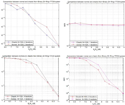
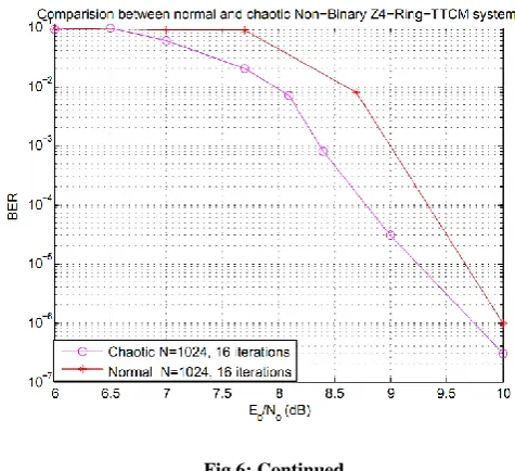
ℤ4-Ring-TTCM Decoder system, the test is applied directly to the computed extrinsic information from each decoder after applying the adaptive control algorithm to this extrinsic information. The goal from this test is to distinguish between regular and chaotic of the extrinsic information. The flow chart of the (0-1) test algorithm can be shown (see Figure 4). The use of adaptive control algorithm in the turbo decoding topology resulted in performance improvement for the ℤ4 -Ring-TTCM system in different number of iterations and fixed number of symbols can be shown (see Figure 5). A comparison in performance improvements between the normal ℤ4-Ring-TTCM system and the chaotic ℤ4 -Ring-TTCM system, for different number of iterations and with 1024 symbols, is shown (see Figure 6).
The performances of the ℤ4-Ring-TTCM scheme-based 3-dimensional decoding algorithm, ℤ4-Ring-TTCM scheme-based chaos technique can be summarized in Table 1, where the coding gains are defined as the (Eb/No) difference,
expressed in decibels, at different values of BERs. The performance of the best scheme in Table 1, is printed in bold, since the performance comparison shows that the ℤ4 -ring-TCM scheme-based chaos technique outperforms the ℤ4 -ring-TCM scheme as shown in Table (1) and shows that the gains improvements are; (0.51 dB, 0.6 dB, 0.03dB) at the BERs of 10-2, 10-4, 10-6 respectively for the scheme with sixteen iterations.
-
-
+
𝐿 1 ∏ 𝑎 𝑡 0 𝑟
𝐿 2 ∏ 𝑎 𝑡 0 𝑟 … …
𝐿 𝑀−1 ∏ 𝑎
𝑡 0 𝑟
𝐿 1 𝑎 𝑡 0 𝑟
𝐿 2 𝑎 𝑡 0 𝑟 … … 𝐿 𝑀−1 𝑎
𝑡 0 𝑟
𝐿 1 ∏ 𝑎 𝑡 0 𝑟
𝐿 2 ∏ 𝑎 𝑡 0 𝑟 … …
𝐿 𝑀−1 ∏ 𝑎
𝑡 0 𝑟 𝐿 1 2 ∏ 𝑎𝑡 0
𝐿 2 2 ∏ 𝑎𝑡 0 … …
𝐿 𝑀−1 2 ∏ 𝑎𝑡 0
𝐿 1 𝑒1 𝑎𝑡 0 𝐿 2 𝑒1 𝑎𝑡 0 … … 𝐿𝑒1 𝑀−1 𝑎𝑡 0
𝐿 1 𝑟 𝑎 𝑡 1
𝐿 2 𝑟 𝑎 𝑡 1 … … 𝐿 𝑀−1 𝑟 𝑎
𝑡 1
-
-
+
𝐿1 1 𝑎𝑡 0 𝐿1 2 𝑎𝑡 0 … … 𝐿 𝑀−1 1 𝑎𝑡 0
𝐿 1 𝑎 𝑡 0 𝑟 𝐿 2 𝑎
𝑡 0 𝑟 … … 𝐿 𝑀−1 𝑎 𝑡 0 𝑟
Multi-dimensional MAP Algorithm Decoder 1
𝐿 1 𝑟 𝑎 𝑡 0 𝐿 2 𝑟 𝑎
𝑡 0 … … 𝐿 𝑀−1 𝑟 𝑎
𝑡 0
𝐿 1 𝑟 𝑎
𝑡 2 𝐿 2 𝑟 𝑎
𝑡 2 … … 𝐿 𝑀−1 𝑟 𝑎
𝑡 2
∏
−1∏
∏
𝐿 1 𝑒2 ∏ 𝑎𝑡 0𝐿 2 𝑒2 ∏ 𝑎𝑡 0 … …
𝐿 𝑀−1 𝑒2 ∏ 𝑎𝑡 0
[image:5.595.44.483.74.723.2]
Smoothing mean square displacement
Determine numerically the asymptotic growth rate Kc
Compute: K= median (Kc)
Chaotic Regular
If K≅
1 0
Compute the mean square displacement of the translation variables pc(t) and qc(t)
Store variables pc(t) and qc(t)
Compute the translation variables pc(t) and qc(t)
Extrinsic information Begin
Fig 5: The performance of the ℤ𝟒-Ring-TTCM system-based chaos technique
[image:7.595.62.542.354.757.2]
Table 1. The performances of the normal and chaotic ℤ𝟒-Ring-TTCM schemes, for sixteen iterations
Number of Iterations
(16)
BER AWGN
channel
Eb / No (dB) Gain (dB)
CM
scheme
CM
Code rate 10-2 10-4 10-6 10-2 10-4 10-6 Modem
ℤ4-RTTCM 1/2 8.51 9.30 10.00 4-PAM
ℤ4-RTTCM
Based chaos
1/2 8.00 8.70 9.70 0.51 0.60 0.30 4-PAM
6.
CONCLUSIONS AND FUTURE
WORKS
The use of non-binary TCM and TTCM codes led to reduction in the effective input block length, since each m bits of binary information correspond to one non-binary symbol for q = 2m, and thus non-binary system can be used with high number of symbols. Non-binary TTCM schemes that have modulation order (M) can achieve an error performance similar to that of binary schemes that have higher order (M), and this is the reason of achieving good performance by non-binary systems over binary systems.
The non-binary turbo decoding algorithm can be viewed as a high-dimensional dynamical system parameterized by a large number of parameters. As an application of the chaos theory developed, it has devised a simple technique to control transient chaos of the non-binary turbo decoding algorithm. This results in a faster convergence and a signicant gain in terms of BER performance.
Binary test for chaos, the 0-1 test is used for testing the extrinsic information of non-binary turbo decoding algorithm, the most powerful aspect of the method, which differs from Lyapunov exponents method, it is independent of the nature of the vector field (or data) under consideration.
The future work can be done by designing a chaotic interleaver to use instead of the algebraic interleaver in the turbo decoder scheme, since, the purpose of the chaotic interleaver is to offer each encoder an uncorrelated or a “random” version of the information, resulting in parity bits from each RSC that are independent. How “independent” these parity bits are, is essentially a function of the type and length/depth of the interleaver.
7.
REFERENCES
[1] C. Berrou and A. Glavieux, „Near optimum error correcting coding and decoding: turbo codes‟, IEEE Transactions on Communications, vol. 44, pp. 1261– 1271, October 1996.
[2] R. Gallager, „Low density parity check codes‟, IEEE Transactions on Information Theory, vol. 8, pp. 21–28, January 1962.
[3] D. J. C. Mackay and R. M. Neal, „Near Shannon limit performance of low density parity check codes‟, Electronics Letters, vol. 33, pp. 457–458, March 1997.
[4] B. Lu, X. Wang, and K. R. Narayanan, „LDPC-based space-time coded OFDM systems over correlated fading channels: performance analysis and receiver design‟, in Proceedings of the 2001 IEEE International Symposium on Information Theory, (Washington, DC, USA), vol. 1, p. 313, 24–29 June 2001.
[5] „Using MIMO-OFDM Technology To Boost Wireless LAN Performance Today‟, White Paper, Data comm Research Company, St Louis, USA, June 2005.
[6] H. Sampath, S. Talwar, J. Tellado, V. Erceg, and A. J. Paulraj, „A fourth-generation MIMO-OFDM broadband wireless system: design, performance, and field trial results‟, IEEE Communications Magazine, vol. 40, pp. 143–149, September 2002.
[7] Bahl, L. R., Cocke, J., Jelinek, F., Raviv, J. Optimal decoding of linear codes for minimizing symbol error rate. IEEE Trans. Inform. Theory, vol. 20, pp.284–287, 1974.
[8] L. E. Larson, Jia-Ming L., and L. S. Tsimring: Digital Communications Using Chaos and Nonlinear Dynamics. Springer Science+Business Media, LLC (2006).
[9] N. Mobini, New Iterative Decoding Algorithms for Low-Density Parity-Check (LDPC) Codes. A thesis submitted to the Faculty of Graduate and Postdoctoral Affairs, Carleton University, Ottawa, Ontario, August, 2011.
[10] R. A. Carrasco and M. Johnston, Non-Binary Error Control Coding for Wireless Communications and Data Storage. UK, John Wiley & Sons, Ltd.2009.
[11] C. Berrou, A. Glavieux, and P. Thitimajshima, „Near Shannon limit error-correcting coding and decoding: turbo codes‟, in Proceedings of the International Conference on Communications,(Geneva,Switzerland), pp. 1064–1070, May 1993.
[12] Bahl, L. R., Cocke, J., Jelinek, F., Raviv, J. Optimal decoding of linear codes for minimizing symbol error rate. IEEE Trans. Inform. Theory, vol. 20, pp.284–287, 1974.
[13] Kuznetsov, Y. A. Elements of Applied Bifurcation Theory. Springer-Verlag, New York, 1995.
[14] G. A. Gottwald and I. Melbourne, “A new test for chaos in deterministic systems,” Proceedings of the Royal Society of London A, vol. 460, no. 2042, pp. 603–611, 2004.