http://dx.doi.org/10.4236/jbcpr.2014.22009
Lecablock, an Alternative Construction
Material for the Exterior Walls of
Passive House
Osama A. B. Hassan
1, Petra Jonsson
21Department of Science and Technology, Linköping University, Norrköping, Sweden 2Petra Jonsson, Lindbäcks bygg, Piteå, Sweden
Email: osama.hassan@liu.se
Received 27 January 2014; revised 28 February 2014; accepted 9 March 2014
Copyright © 2014 by authors and Scientific Research Publishing Inc.
This work is licensed under the Creative Commons Attribution International License (CC BY). http://creativecommons.org/licenses/by/4.0/
Abstract
In this paper it is attempted to investigate the Leca blocks as sustainable construction material for the exterior walls of passive house. The building physical properties of Leca design wall structure are studied along with the environmental impact and load-bearing capacity. To compare the re-sults, a similar analysis is carried out considering the traditional wooden wall construction of pas-sive houses. The results showed that Leca design wall structure can be an alternative sustainable solution to the traditional wooden wall structure of passive house, mainly due to its low U-value, its ability to handle moisture, and comparable structural load-bearing capacity. However, the wooden wall structure is more environmentally friendly than the Leca blocks due to its lower emissions to the environment and reduced energy use, especially during the manufacturing proc-ess.
Keywords
U-Value, Moisture, Thermal Bridges, Passive House, Energy Efficiency, Load-Bearing Capacity
1. Introduction
A number of studies addressed the issues of heat transport through the building materials of buildings; see [1]-[4]. In addition to the energy aspect, the choice of construction materials is another criterion that should be considered in the design of passive house buildings. Al Sanea and Zedan [5] investigated the influence of mortar joints in insulated building walls and the extent these can act as thermal bridge in walls. Mlakara and Strancarb [6] studied the temperature and humidity profiles in passive-house building blocks and found that that ventilated wooden facades, in comparison with classical façade plaster, protect the building blocks from high thermal loads. However, a judicious choice on using specific construction materials is not only governed by the building phys-ical properties but also on other technphys-ical properties that can be a decisive factor such as structural and environ-mental properties.
Evidently, there are a number of criteria that can be set on the construction materials and structures to satisfy the requirements for a passive house building. In the long term technically, the construction materials should sa-tisfy the functional demand of the building as well as being environmentally sustainable. Important criteria can, thus, be air tightness, thermal and moisture properties, load-bearing capacity as well as environmental impact of the constructions.
Wood has always been a material termed as a “natural building material” and is common in the construction today’s passive houses; see e.g. [7]. However, to build a wooden wall structure to satisfy the international re-quirements for passive buildings implies an extensive and expensive process. Consequently, it will be interesting to study alternative solutions to meet these requirements and this article is an attempt in this context. One of such potential solutions is the use of Leca blocks for the construction of exterior walls of passive house.
Leca blocks are prefabricated elements, made of lightweight concrete on the basis of Leca (light expanded clay aggregate) mixed with cement, sand and water, and produced in rotary kiln at about 1200˚C. Using of Leca aggregate results in decreasing the concrete density. Due to its lightness and structure, the material has good thermal and acoustic insulation and fire-proofed stability. It is therefore used mainly in the construction of basement walls, floors, internal partition walls and ceilings.
In this paper it is attempted to investigate the Leca blocks as sustainable construction material for the exterior walls of passive house. The building physical properties of Leca design wall structure such as heat and moisture transport, air tightness are studied along with the environmental impact and load-bearing capacity. To compare the results, a similar analysis is carried out considering the traditional wooden wall structure of passive houses.
2. Theory
2.1. Heat Transfer
The total thermal resistance of a homogeneous wall construction that consists of a number of layers may be ex-pressed as
(
) (
)
(
)
(
2)
1 1 2 2 ... m K W
tot si res res se
R =R + d λ + d λ + + d λ +R
(1)
where Rsiis the internal surface resistance, Rse the external surface resistance, d and λ is the layer thickness and thermal conductivity, respectively. The thermal transmittance (U-value) is calculated accordingly
(
2)
1 tot W m K
U= R
(2)
The building’s total heat flow rate through the building envelope can be evaluated as [8] [9]
(
W K)
i i i i i
i i i
Q= U A + ψ l + χ ∆T
∑
∑
∑
(3)
where U is the thermal transmittance for each element with a surface area (W/m2K), 𝐴𝐴 is the surface area for each of those elements (m2), 𝜓𝜓 is the linear thermal transmittance for each element where only its length is con-sidered (W/mK), 𝑙𝑙 is the length for each of those elements (m), 𝜒𝜒 is the point thermal transmittance for each element where only its position is considered (W/K), and Δ𝑇𝑇 is the temperature difference (K) through the building ( indoor air and outdoor air).
(
)
2 W mK D Q L T =∆ (4)
For a 2D analysis [8] [9] to analyse the thermal bridges in junction (wall-floor), the heat flow rate Q is calcu-lated from a heat transfer simulation, so that the linear thermal transmittance of the junction should be obtained as
(
)
2D W mK
i i i
L U l
ψ = −
∑
(5)
where Ui is the U-value (thermal transmittance) for the individual part of the junction. For junction between a wall and a slab, Equation (5) may be written as
2D
w w f fl
L U h U l
ψ = − −
(6)
where Uwis the thermal transmittance of the wall (W/m
2
K), hw is the height of the wall (m), Uf is the thermal transmittance of the floor (W/m2K), lfl is the length of the floor (m), L
2𝐷𝐷
is the thermal coupling coefficient for the whole analysed detail (W/m).
For this study, it is used HEAT2®[10] to calculate the linear thermal transmittance ψ and simulate the heat flow transfer through the junction (wall-floor), based on the simplified procedure of EN ISO 10211:2007 [9].
2.2. Moisture Transfer
The steady state diffusive flux through a multi-layered wall may be written as [11]
(
2)
1 2 1 2
,
kg m s v
v tot
v v v v
g
d Z
δ − −
= = (7)
(
)
, 1 , s m N iv tot vi ve
i v i
d
Z Z Z
δ =
=
∑
+ +(8)
( )
% sv RH
v
=
(9)
where v1 is the humidity by volume at one side of the layer and v2 on the other side, δv is the vapour permeability
of the material, d is the layer thickness, Zv is the total water vapour resistance of the layer, Zvi is the resistance at the inner side of the building envelope and Zve the corresponding one at the exterior side, RH is the relative hu-midity, vs is humidity by volume at saturation, v is humidity by volume. To calculate the moisture transfer through the construction, a table method is used in which the relative humidity at the boundary between layers of the wall is calculated using Equation (7) - Equation (8); more details on the method can be found in [11]; see also [26].
2.3. Load-Bearing Capacity
For the selected design situation, an ultimate limit state of rupture of a wall section will be verified. The verifi-cation of structural resistance may be set to
(
kN m)
d d
R ≥E (10)
where Ed is the design value of the effect of actions such as moment and Rd is the design value of the corres-ponding resistance. The ultimate limit state (STR) for the wall may be used to verify moment and shear capaci-ties of the beam at all points, where the strength of construction materials of the wall structure governs. The de-sign load value due to the combination of actions for the STR Ultimate Limit States may be expressed as [12] [13]
(
)
0 ,
1.35 1.5 kN m
d d k d k i
i
Q =γ G +γ
∑
ψ Q (11)(
)
,1 0 ,
1.2 1.5 1.5 kN m
d d k d k d k i
i
Where γd is partial safety factor of unfavourable action, Gk is the characteristic value of permanent action
(self-weight of construction works), Qk,1is the characteristic value of leading variable action, Qk,i is the charac-teristic value of the accompanying variable action i, ψ0 is factor for combination value of a variable action.
The variable actions on the structure are mainly snow load, wind load and imposed loads. The characteristic snow load on the roof may be expressed as
(
2)
kN m
i e t k
s=µC C s
(13)
where μ is shape coefficient of the roof, skis the fundamental value of snow load for a given location, intended as the upper value of a random variable, for which a given statistical distribution function applies, Ct and Ce are thermal and exposure coefficients.
The characteristic wind action obeys
( )
(
2)
kN m
e p p
w =q z c (14)
where qp(z) is the peak velocity pressure for the given location (site basic velocity, terrain roughness, orography etc.), function of the reference height z, cp is pressure coefficient (internal or external) depending on the location of the reference area in the structure.
The characteristic value of the imposed loads for the building depends on the categories of occupancy [12].
2.4. Air Tightness
Air tightness is a building physical property that affects air movement in and through the building envelope. This air movement through cracks, openings, leaks in the building envelope affect heat and moisture flow in building [14]. Consequently, a passive house design requires high thermal insulation, high air-tightness with ex-cellent indoor air quality through efficient ventilation system in both winter and summer. For this study, the fan pressurization including blower door system [15] is the method used for measuring air tightness of the building envelope. In this method, the air tightness involves a depressurising a building to a pressure difference of 50 Pa. As the pressure differential reaches 50 Pa, the air leakage rate or permeability of the external envelope of the building can be evaluated. The Swedish requirement for the air leakage rate of passive house is 0.3 l/sm2[16] while the passive house institute (PHI) suggests an air exchange rate, n50 = 0.6 hr−1, in order to consider a
build-ing airtight [16]; an n50 value of 0.6 indicates approximately that a maximum of 60% of the complete building
air volume can escape per hour.
In a broader sense, for wall structures, the air leakage depends on the air leaks between the component parts as well as the boundary between the wall and connections.
3. Investigation
For the study, the timbre frame wall structure is shown in Figure 1. This wall construction is the typical for pas-sive house used in Sweden (see e.g., [17] and [18]). The thermal insulation is cellulose. The OSB (Oriented Strand Board) is wood particle board formed by layering strands of wood in detailed orientations to create an airtight layer. The façade leaf consists of wood fibre board mounted on horizontal aluminium flange.
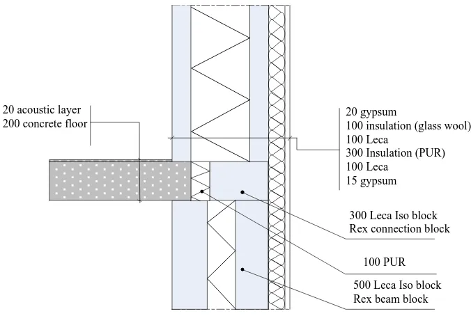
The Leca block wall construction is shown in Figure 2. The Leca wall consists of a plastering mortar of nat-ural gypsum, Leca ISO block REX, thermal insulation (glass wool), an intermediate thermal insulation of po-lyurethane and an outer facade system. In Figure 1 and Figure 2, it is also shown the floor structure for both types of wall. For the Leca block wall, the floor structure is composed of reinforced concrete while for the tim-bre wall; the floor is made mainly of wood. Figure 3 shows an example picture of the investigated building LECA block material.
4. Results and Discussion
4.1. Timbre Frame Wall Construction
4.1.1. Thermal Properties
10 facade leaf air grap
32x70 horiz.alum. flange c/c 750 34x45 vertical batten, c/c 750 35 fibre board
400 mm I-beam HI400 400 insulation 22 OSB 95 insulation
45x95 timbre stud, c/c 600 12 OSB
13 gypsum 2x12.5 floor gypsum
36 acoustic layer 209 construction timbre floor
Glulam 90x450 12 PUL
Figure 1. Cross-section through timber frame wall construction. All dimensions are in mm.
20 gypsum
100 insulation (glass wool) 100 Leca
300 Insulation (PUR) 100 Leca
15 gypsum 20 acoustic layer
200 concrete floor
300 Leca Iso block Rex connection block
100 PUR
500 Leca Iso block Rex beam block
Figure 2. Cross-section through the Leca block wall and floor construction. All dimensions are in mm.
junction. For the simulation, the temperature difference on both sides of the wall structure, ΔT = 1 K.
The results show that timbre wall has good thermal insulating properties. A passive house is designed so that heat loss should be reduced through the building envelope. This can be done by producing an airtight and well-insulated wall construction that ensures a U-value of up to 0.1 W/m2K [17].
[image:5.595.143.481.325.552.2]Figure 3. Leca ISO block REX. Source: www.weber.se.
0.2 0.3
0.40.50.6
0.1
0.7 0.8 0.9
4
1
2
3 5 7
6
[image:6.595.202.428.89.253.2]8
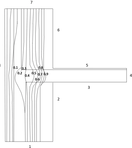
Figure 4. Simulated isotherms of the temperature difference through connec- tion between slab and exterior timbre wall (Figure 1). The length of boun- daries: 2 (1.01 m); 3 (1.378 m); 5 (1.377 m); 6 (1.194 m); 8 (2.45 m).
4.1.2. Air Tightness
The measured air leakage rate for the building is 0.15 l/sm2 [21], which is below the international requirements for air tightness in passive houses.
4.1.3. Moisture
[image:6.595.176.454.272.587.2]Table 1. Layer properties of the timbre wall.
Material Thickness (mm) λ (W/m˚C) Density (kg/m3)
Gypsum board 13 0.22 780
OSB board 12 0.13 580
Timber stud 95 0.14 650
Insulation 95 0.039 56
OSB board 22 0.13 580
I-beam 400
0.04 600
Insulation 400 56
Fibre board 35 0.049 500
Table 2. The distribution of relative humidity through the timbre wall. The row line of the humidity column concerns the
boundary between two consecutive layers..
Material Relative humidity (%)
Indoor 62
62 Gypsum board
62 OSB board
60 Insulation
63 OSB board
62 I-beam + Insulation
78 Fibre board
77 Outside
77
20˚C and 62%. The corresponding outdoor climate is 14.6˚C and 77%.
The results show that the projected exterior wall will not have a risk of interstitial condensation. However, the relative humidity at the boundary between insulation and fibre board exceeds the critical moisture content for wood, which is 75% [22]. As wood is an organic material, there will thus be risk for microbial attack at RF > 75% in form of mould and mould fungus. The fungus itself does not affect the properties of the wood but is un-healthy to breathe. Moreover, the wood bearing capacity may deteriorate in the long run.
4.1.4. Environmental Impact
Wood is the oldest building materials in Sweden. Because of its renew ability and re-usability, it is considered as an environmentally friendly resource material. The production energy of wood as a building material is much lower than other materials as the energy in sawmills is mainly derived from renewable resources (about 80% biofuel). The process that consumes most of the production energy is the drying of boards and planks. The energy consumption is about 330 kWh/m3. When the wood has reached its useful life, it can either be reused or recycled. OSB boars consists of 75% of sawmill by-products and the rest is made up of raw timber from sus-tainably managed forests [23] [24]. The thermal insulation (cellulose) comes mainly (about 94%) from unsold newspapers and thus helps minimize the use of resources. Moreover, the material is fully recyclable at the end of its usage [25]. In some cases in practice, there can be additives of boron and boron salts to this type of insulation, which has normally a negative impact on the human hormone balance and reproduction [18]. Untreated wood emits no harmful emissions at normal conditions but in case of moisture damage due to mould fungus, hazard-ous emissions can be emitted into the environment. The OSB board is known to emit emissions in the form of formaldehyde from the glue that holds the veneer chips. However, the studied wall construction does not contain formaldehyde and the selected bond material is resin [25] [26].
4.1.5. Load-Bearing Capacity and Design Load
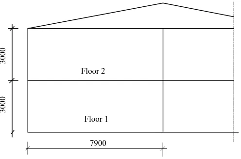
Consider a 2 storey school building as shown in Figure 5. The actions loads on the building are presented in
[image:7.595.86.540.254.402.2]3000
3000
7900 Floor 2
Floor 1
Figure 5. Cross-section through a 2-storey building.
Table 3. Permanent actions.
Member Gk (kN/m2) Safety factor
d
γ
Roof 1.5 3 1
Intermediate floor (timbre) 1.0 2 0.91
Intermediate floor (concrete) 1.4 2 0.91
Table 4. Variable actions.
Action Qk,1
Snow load 14.1 kN/m
Imposed load 6 kN/m
Wind load 0.34 kN/m2
by lightweight
timbre beam, which has a load-bearing capacity, Rd= 56 kN/m.The combination of actions calculated according to Equation (11) and Equation (12) yielda design load Qd= 46 kN/m. This implies that the wall will have a sufficient load-bearing capacity in this case.
4.2. External Wall, Leca ISO Block Rex
[image:8.595.191.439.84.248.2]4.2.1. Thermal Properties
Table 5 presents the thermal conductivities of the construction layers, used to calculated the U-value. The U-value for the Leca wall is estimated to be 0.058 W/m2K.The linear thermal transmittance of the thermal bridge of the junction between the floor and wall, ψ = 0.016 W/mK.Figure 6 shows the temperature difference through the junction. For the simulation, the difference in temperature on each side of the structure, ΔT = 1 K.
The results show that Leca block wall has lower U-value than the timbre wall, discussed earlier. Technically, Leca block contains air-filled pores with the air-filled clayey cells, which contribute to its insulation properties. A pure solid Leca block has not significantly large thermal insulation, but in combination with sufficiently thick insulation, the structure will have sufficient insulation to meet the requirement for passive houses. The insulation in Leca block consists of polyurethane (PUR) produced by foaming a blowing agent. With this formed gas in a closed cell system, the insulation capacity will be improved. However, as moisture is transferred by diffusion through the wall, there can be a risk that these gases are replaced with air and the insulation will likely deteri-orate with time [26]. Therefore it is important to have airtight wall layers in the construction.
4.2.2. Air Tightness
0.1 0.2
0.3 0.4 0.5 0.7
0.8 0.9 0.6
8
1
2
3
4 5
6 7
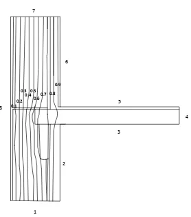
[image:9.595.206.421.87.328.2]Figure 6. Simulated isotherms of the temperature difference through the connection between slab and exterior Leca block wall (Figure 2). The length of boundaries: 2 (1 m); 3 (1 m); 5 (1 m); 6 (1 m); 8 (2.2 m).
Table 5. Layer properties of the Leca block wall.
Material Thickness (mm) λ (W/m˚C) Density (kg/m3)
Internal gypsum board 15 0.1 780
Leca 100 0.2 600
Polyurethane 300 0.023 50
Leca 100 0.2 600
Glass wool 100 0.032 35
External gypsum board 20 0.1 780
4.2.3. Moisture
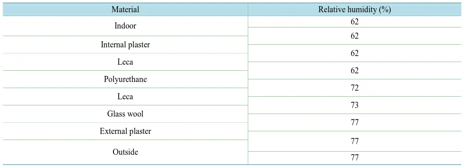
To compare both walls, the same indicated climate conditions are considered. Table 6presents the relative hu-midity profile in the wall section as a result of moisture transfer by diffusion. The results concern the month August in Umeå, Sweden. The indoor temperature and relative humidity are 20˚C and 62%. The corresponding outdoor climate is 14.6˚C and 77%. The results show that the Leca wall will not have a risk of interstitial con-densation.
As Leca is an inorganic material, the risk of mould fungus attack on material surfaces is relatively low, as compared with wood. The critical relative humidity level for Leca block may be compared with concrete, which is 90% [27].
However, high moisture levels could lead to a deterioration of the material’s load-bearing capacity. Compo-nents that are most likely to be damaged are the insulation layers [18]. In practice, the combination of insulation and plaster can provide a strong protection against weather conditions.
4.2.4. Environmental Impact
[image:9.595.93.538.402.495.2]Table 6. The distribution of relative humidity the Leca block wall. The row line of the humidity column concerns the boun- dary between two consecutive layers.
Material Relative humidity (%)
Indoor 62
62 Internal plaster
62 Leca
62 Polyurethane
72 Leca
73 Glass wool
77 External plaster
77 Outside
77
the wall structure emits no measurable emission into the environment and doesn’t there by affect the indoor cli-mate. However, emissions to the air, soil or water have been detected during the production phase; it consists of carbon, sulphur and nitrogen oxides [28] [29].
Leca is a natural product of calcium carbonate mud. In the production of Leca ISO block Rex, building prod-uct declaration [28] [29] specified that the energy used for extraction of raw materials is about 400MJ/m2 and consists mainly of fossil fuels. The design lifetime of the Leca block is estimated to be higher than 50 years, without the need for considerable efforts for operation and maintenance. When life cycle reaches its end, or in the event of demolition, the entire block can be recovered by separating the constituent materials. The light- weight aggregate can also be reused as filling material.
Polyurethane can be leveraged by recovering energy in a combustion plant. The interior plaster has a design life of 50 years and higher, and can be recycled after use time. The demolition requires special action because it contains small amounts of substances that can be harmful to fish and bacteria due to the pH change, when it comes in contact with water [28] [29].
4.2.5. Load Bearing Capacity
For comparison, consider the same building in Figure 5. The actions loads on the building are presented in
Table 3and Table4. Eurocode has only computational models for massive lightweight aggregate blocks and cannot be used for calculating Leca blocks bearing capacity. However, Weber [30]-[32] developed a method for the design of structures with Leca block. For the building (Figure 5) constructed with Leca block walls, the load-bearing capacity (Rd) for Floor 1 and 2 is 78 kN/m and 56 kN/m, respectively. The combination of actions calculated according to Equation (11) and Equation (12) yielda design load, Qd= 42.5 kN/m for Floor 1 and 28.3 kN/m for Floor 2, respectively. This implies that the wall will have a sufficient load-bearing capacity.
5. Conclusions
5.1. Thermal Properties
The calculated U-values for each wall structure satisfy the requirements set for exterior walls in passive houses. The U-value of the Leca block wall was found to be lower than the U-value of the timbre wall. What is not taken into account in these calculations is how this value is constant overtime. For example, the cellulose in the wooden wall will have its thermal function reduced once exposed to moisture.
5.2. Moisture and Air Tightness
The results for both walls show that the wall components will not have a risk of interstitial condensation. The distribution rate of moisture through the construction of both walls is almost similar. However, for the timbre wall, the critical moisture content is exceeded during the climate conditions in August, which can render the wall susceptible to moisture damage. This is not case for the Leca block wall under the same climate conditions. On the other hand, the evaluation of air tightness for both walls is comparable.
5.3. Environmental Impact
To compare two different exterior wall structures has been a major challenge related to the constituent material to consider on the basis of the actual parameters. Since the studied wooden wall comprised largely of wood and insulation of cellulose, it is these materials studied. Merely studying the material with different geometrical properties in the structure may give partially misleading results, but it can be a good starting point for the selec-tion of different design soluselec-tions.
None of the constituent materials in the investigated wall structures emit emissions, which are harmful to health or affect the indoor climate. However, there were traces of isocyanates in the Leca block insulation of polyurethane, which can be harmful if it were in large concentrations. The timbre wall is more environmentally friendly than the Leca block wall, with respect to energy use. In this context, the energy used for manufacturing wood consists of about 80% biofuel, renewable energy, compared to the energy use for manufacturing Lecab-lock, which corresponds to about 67% fossil fuel, non-renewable energy; this energy is to generate high temper-ature for processing the Leca. Of course, one can here use biofuel, but this would mean a much longer produc-tion time related to a slower heating.
5.4. Load-Bearing Capacity
Both walls have been found to have a sufficient load-bearing capacity to resists the exerted vertical loads on the structure.
5.5. Concluding Remarks
Every design solution has its pros and cons, which mean that, depending on the requirements of the current building, both can be selected. At any rate, the results indicate that the studied Leca block wall can be an alter-native sustainable design solution for passive house building.
To extend this work, forthcoming studies may include other design elements throughout the building and not just exterior walls, especially with respect to heat transmission losses. Additional calculations with respect to the stability of the structures due to horizontal actions can also be carried out. In many cases in practice, the trans-verse walls distance will depend on the design wind load and is the decisive factor to judge the horizontal satia-bility of the building.
Other aspects, which can be of interest to investigate is the sound transmission through the wall constructions and the fire resistance of both wall structures. Especially for latter case, evidently, due to its lightness and struc-ture, the Leca material has good fire-proofed stability as compared with wood, which is susceptible to fire.
Finally, for a comprehensive scheme of the assessment of environmental impact for both wall constructions, one may investigate the environmental impact due to the transport of materials from the production plant to the construction site.
References
[1] Gea, H., McClungb, V.R. and Zhangc, S. (2013) Impact of Balcony Thermal Bridges on the Overall Thermal Per-formance of Multi-Unit Residential Buildings: A Case Study. Energy and Buildings, 60, 163-173.
http://dx.doi.org/10.1016/j.enbuild.2013.01.004
[2] Larbi, A.B. (2005) Statistical Modelling of Heat Transfer for Thermal Bridges of Buildings. Energy and Buildings, 37, 945-951. http://dx.doi.org/10.1016/j.enbuild.2004.12.013
[4] Zalewskia, L., Lassuea, S., Roussec, D. and Boukhalfaa, K. (2010) Experimental and Numerical Characterization of Thermal Bridges in Prefabricated Building Walls. Energy Conversion and Management, 51, 2869-2877.
http://dx.doi.org/10.1016/j.enconman.2010.06.026
[5] Al-Sanea, S.A. and Zedan, M.F. (2012) Effect of Thermal Bridges on Transmission Loads and Thermal Resistance of building Walls under Dynamic Conditions. Applied Energy, 98, 584-593.
http://dx.doi.org/10.1016/j.apenergy.2012.04.038
[6] Mlakara, J. and Štrancarb, J. (2013) Temperature and Humidity Profiles in Passive-House Building Blocks. Building and Environment, 60, 185-193. http://dx.doi.org/10.1016/j.buildenv.2012.11.018
[7] Crawford R.H. and Stephan, A. (2013) The Significance of Embodied Energy in Certified Passive Houses. World Academy of Science, Engineering and Technology, 78.
[8] EN ISO 14683:2007—Thermal Bridges in Building Constructions—Linear Thermal Transmittances—Simplified Methods and Default Values, SIS, Brussels, Belgium, 2007.
[9] EN ISO 10211:2007—Thermal Bridges in Building Construction—Heat Flows and Surface Temperatures—Detailed Calculations), SIS, Brussels, Belgium, 2007.
[10] Blomberg, T. (2000) HEAT2. A PC-Program for Heat Transfer in Two Dimensions. Manual with Brief Theory and Examples [online]. http://www.buildingphysics.com/manuals/HEAT2_5.pdf
[11] Hagentoft, C.E. (2010) Introduction to Building Physics. Studentlitteratur, AB, Lund.
[12] The Institution of Structural Engineers (TISE) (2010) Manual for the Design of Building Structures to Eurocode 1 and Basis of Structural Design. UK.
[13] EN 1991-1: Eurocode 1 (2005) Actions on Structures—Part 1-4: General Actions: Part 1-1: General Actions— Densi-ties, Self-Weight, Imposed Loads for Buildings, Part 1-3: General actions—Snow Loads, Eurocode 1: Actions on Structures—Part 1-4: General actions—Wind Actions. The European Union.
[14] Hassan, O.A.B. (2013) An Alternative Method for Evaluating the Air Tightness of Building Components. Building and Environment, 67, 82-86. http://dx.doi.org/10.1016/j.buildenv.2013.05.007
[15] ASHRAE, Standard 119 (1988) Air Leakage Performance for Detached Single-Family Residential Buildings. Ameri-can Society of Heating, Refrigerating and Air Conditioning Engineers.
[16] Passivhuscentrum (2009) FEBY Kriteriejämförelse av Passivhus.
http://www.passivhuscentrum.se/sites/default/files/jamforelse_mellan_svenska_och_internationella_passivhuskriterier_ 0.pdf
[17] Andrén, L. andTirén, L. (2012) Passivhus: En handbok om energieffektivt byggande. Svensk Byggtjänst.
[18] Bokalders, V. and Block, M. (2009) Byggekologi: Kunskaper för ett hållbart byggande. Svensk Byggtjänst, Stockholm.
[19] Steico (2013) Steico Universal Sarking and Sheating Boards.
http://www.steico.com/fileadmin/steico/content/pdf/Marketing/UK/Product_information/universal/STEICOuniversal_e n_i.pdf
[20] Fröbel, J. and Beyer, G. (red.) (2004) Att välja trä: trävaror och träprofiler till bygget. Skogsindustrierna, Stockholm.
[21] Jonsson, P. (2013) En alternative lösning till yttervägger i ett passivhus. B.Sc Thesis, Umeå University, Umeå.
[22] Burström, P.G. (2007) Byggnadsmaterial: Uppbyggnad, tillverkning och egenskaper. Studentlitteratur, Lund.
[23] Egger (2013) Egger Construction. Wood Based Panels for Use in Timber Construction.
http://www.egger.com/downloads/bildarchiv/37000/1_37753_BR_EGGER-HOLZBAU_EN.pdf
[24] Egger (2013) Naturally Egger. Sustainable Construction and Healthy Living with Egger Wood-Based Materials.
http://www.egger.com/downloads/bildarchiv/37000/1_37654_BR_Environment-Sustainability_EN.pdf
[25] iCell (2013) Insulation Technology. Made in Sweden.
http://www.icell.nu/filer/iCell-cellulosa-isolering-broschyr-02.pdf
[26] Petersson, B. (2009) Tillämpad byggnadsfysik.Studentlitteratur, Lund.
[27] Hassan, O. (2012) Kompendiums i byggnasmaterial. Institute of Applied Physics and Electronics, Umeå University, Umeå.
[28] Byggvarudeklaration BVD3(2007) Enligt kretsloppsrådets riktlinjer 2007. Leca ISO-block Rex.
http://www.weber.se/uploads/tx_weberproductpage/8b16ac501f3845aabbda39cb248e65ea.pdf
[29] Byggvarudeklaration BVD3 (2007) Enligt kretsloppsrådets riktlinjer 2007. Weber.therm 342 fasadbruk.
http://www.weber.se/uploads/tx_weberproductpage/bbf9cb229911447c968b990ab5804b3a.pdf
[30] Weber (2013) Leca Block Projekteringsanvisning.
[31] Weber (2013) Produktblad Leca ISO-block Rex.
http://www.weber.se/uploads/tx_weberproductpage/printable_sheet_Leca_reg__Isoblock_Rex.pdf.
[32] Weber (2013) Produktblad Serporoc. Sevriges ledande fasadsystem.
http://www.weber.se/fileadmin/user_upload/pdf/fasad/broschyrer/serporoc.pdf
[33] Passive House Institute (PHI) Thermal Bridges.
http://passipedia.passiv.de/passipedia_en/basics/building_physics_-_basics/heat_transfer/thermal_bridges