A Survey on Congestion Notification Algorithm in Data
Centers
Satish D. Pawar
Research Scholar
Government Engineering College Aurangabad
Pallavi V. Kulkarni
Asst. Professor
Government Engineering College Aurangabad
ABSTRACT
Now days, due to fast exploitation of modern data center networks (DCNs), Ethernet is most prominently used than the conventional storage networking technologies like Fiber Channel and Infiniband. Low-loss, low-delay operations are key aspect of these conventional technologies that make them suitable for datacenter. Accordingly IEEE 802.1 standards committee is developing new specification for congestion management for Ethernet in datacenter networks. Backward Congestion Notification (BCN), Forward Explicit Congestion Notification (FECN), Enhanced Forward Explicit Congestion Notification (E-FECN), Quantizes Congestion Notification (QCN), Approximate Fair Quantizes Congestion Notification (AF-QCN) and Fair Quantizes Congestion Notification (F-QCN) is six proposals. Each of the proposals has its own advantages and disadvantages.
In this paper, we provide a comprehensive survey of the most recent research activities in DCNs, with emphasis on the network congestion notification algorithms. We present a brief overview of the congestion problem along with previously proposed solutions.
General Terms
Data center networks (DCNs), data center congestion notification.
Keywords
Congestion notification, backward congestion notification (BCN), quantized congestion notification (QCN).
1.
INTRODUCTION
Data centers, facilities with communications network equipments and servers for data processing and/or storage, are common and essential to provide a myriad of services and applications for different private, government, and non-profit systems. They are used and deployed in nearly every sector of the economy, e.g., financial services, universities, media and government institutions. Many large data center networks (DCNs) have been built in recent years to host online services such as online gaming and web search, distributed file systems such as Google File System (GFS), and distributed Storage System such as BigTable and MapReduce [1]. DCNs are growing rapidly, and the number of servers in DCNs is expanding at an exponential rate. Google hosted approximately 450,000 low-cost commodity servers running across 20 datacenters in 2006 [2], and Microsoft is doubling the number of servers every 14 months. With fast deployment of modern high-speed low-latency large-scale DCNs, many problems have been observed in DCNs, such as DCN architecture design, congestion notification, TCP Incast, and power consumption [3]. This survey/tutorial focuses on addressing the above congestion notification issues.
The paper organized as follows: We describe Congestion Control in Data Centers in section 2. Section 3 compares different congestion notification algorithms proposed for DCNs. Section 4 summarizes some characteristics of congestion notification algorithm Finally, Section 5 concludes the paper.
2.
CONGESTION CONTROL IN DATA
CENTERS
Due to the inherent merits of Ethernet, such as low cost, ubiquitous connectivity, and ease of management, Ethernet has become the primary network protocol for computer to computer communications in a DCN. However, Ethernet was designed for best-effort transmissions that may drop packets when the network or switches are busy. In order to address issues raised within a data center, such as increasing demand for higher bandwidth and performance, and low latency interconnect for high performance cluster computing, new Ethernet protocols are being developed by two separate standards bodies, the Internet Engineering Task Force (IETF) [4] and the IEEE Data Center Bridging Task Group of IEEE 802.1 Working Group [5]. Conventionally, transport protocols, such as TCP, are responsible for reliable transmissions in IP networks. Thus, one area of Ethernet extensions is to provide congestion notification to enhance transport reliability without penalizing the performance of transport protocols. Therefore, congestion notification is a Layer 2 traffic management protocol that monitors the queuing status at the Ethernet switches and pushes congestion to the edge of the network at where the transmission rate limiters shape the traffic to avoid frame losses. Reliable transport protocols, such as TCP that has congestion control mechanism, can also benefit from congestion notification protocols since it can react to congestions in a timelier manner. With the increase of Ethernet link rate to 10 Gbps in data centers, congestion notification protocols are also able to enhance the bandwidth usage more effectively. Project IEEE 802.1Qau is concerned with specifications of an Ethernet Layer or Layer 2 congestion notification mechanism for DCNs deliberated in the IEEE Data Center Bridging Task Group. Several congestion notification algorithms have been proposed, e.g., BCN [6], FECN [8], enhanced FECN (E-FECN) [9], QCN [10], AF-QCN [11] and FQCN [12]. The system models of these congestion notification algorithms as shown in below Figure; BCN, FECN, E-FECN, QCN, AF-QCN and FAF-QCN are all queue-based congestion notification algorithms. They all assume that congestion detector is integrated into the switch, where congestion happens.
feedback messages received from switches. In this section, we will summarize and compare the congestion notification algorithms proposed for Ethernet extensions in data centers.
3.
CONGESTION CONTROL
MECHANISM: RELATED WORKS
3.1
Backward Congestion Notification
(BCN)
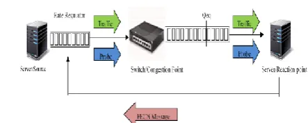
[image:2.595.57.280.223.329.2]The BCN mechanism as shown in Fig. 1 for DCNs was introduced by Bergasamo et al. at Cisco [6]. BCN is also known as Ethernet Congestion Manager (ECM) [7]. BCN works in three phases: Congestion Detection, Signaling, and Source Reaction.
Fig. 1: BCN system model
3.1.1
Congestion Detection
Two thresholds (equilibrium queue length) and (severe congestion queue length) are used to indicate tolerable congestion levels at the switch. The switch samples the incoming packets with probability . When a packet is sampled, the congestion measure is calculated as
, where ,
, denotes the instantaneous queue-size,
and denote the number of arrived and departed packets between two consecutive sampling times, respectively and is a non-negative constant weight.
3.1.2
Backward Signaling
The arriving packets at the switch are sampled with probability and for each sampled packet the feedback BCN message, which uses the 802.1Q tag format [6], is generated as follows:
If the packet doesn’t contain rate regulator tag
If , no BCN message is sent.
If , normal BCN message is sent.
If , BCN STOP message is sent.
if the packet contains rate regulator tag
If and the CPID field in the 802.1Q tag, which is the ID for the congestion point, matches with this switch’s ID, a positive BCN message is sent.
If , normal BCN message is sent.
If , BCN STOP message is sent.3.1.3
Source Reaction
When a STOP message is received at the source, the rate regulator stops sending packets for a random period, and recovers with a rate of C/K, where C is the capacity of the bottleneck link, and K is a constant depending on the number of flows in the network. When a BCN normal message is received at the source, the rate regulator adjusts its rate by using a modified Additive Increase and Multiplicative Decrease (AIMD) algorithm as follows:
Where represents the increase rate unit parameter, and and denote the additive increase and the multiplicative decrease gain parameters, respectively.
3.2
Forward Explicit Congestion
Notification (FECN) and Enhanced FECN
(E-FECN)
As shown in Fig. 2, FECN is a close-loop explicit rate feedback control mechanism. All flows are initialized with the full rate. The sources periodically probe the congestion condition along the path to the destination. The rate field in the probe message is modified along the forward path by the switches if the available bandwidth at each switch in the forward path is smaller than the value of the rate field in the probe message. When the sources receive the probe messages returned back from the destination, the rate regulator adjusts the sending rate as indicated in the received message. All flows are treated fairly in FECN since the same rate is advertised by the switch. FECN uses rate based load sensor to detect congestion. At the congestion point, the switch periodically measures the average arrival rate and the instantaneous queue length during the interval, where is the index of the measurement interval. The effective load can be measured as where C is the link capacity, and
is the hyperbolic queue control function which is defined below to ensure a constant queue length:
Where a, b, c are constants. For .Then, the queue control function attempts to aggressively increase the advertised rate. For , generally .Then, the queue control function attempts to aggressively decrease the advertised rate. The bandwidth allocation can be calculated as
Where could be thing of as the available effective bandwidth, and is the effective number of flows. If
where r is the rate value in the rate discovery probes, then the rate value in the probe message will be marked with .
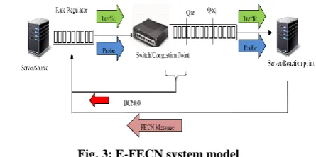
[image:2.595.317.539.599.688.2]Fig. 3: E-FECN system model
As shown in Fig. 3, almost all E-FECN operations assume the same operations as those in FECN, except that, the switches are allowed to feed back to the source directly under severe congestion in E-FECN. Under severe congestion, the switch sends a specific BCN00 message, which causes the rate regulator at the source to reduce to a low initial rate upon receiving this BCN00 feedback message.
3.3
Quantized Congestion Notification
(QCN)
[image:3.595.54.282.394.478.2]The QCN algorithm is composed of two parts as shown in Fig. 4 switch or congestion point (CP) dynamics and rate limiter (RL) dynamics. At CP, the switch buffer attached to an oversubscribed link samples incoming packets and feeds the congestion severity level back to the source of the sampled packet. At one traffic source, RL decreases its sending rate based on the congestion notification message received from CP, and increases its rate voluntarily to recover lost bandwidth and probe for extra available bandwidth.
Fig. 4: QCN system model
3.3.1
The CP Algorithm
The goal of CP is to maintain the buffer occupancy at a desired operating point, which is the queue threshold for equilibrium. At time t, CP samples the incoming packets with a sampling probability , and computes the congestion feedback value . The sampling probability is initialized to 1%, and is updated after computing the congestion feedback value at each sampling event. Denote an as the instantaneous queue length in bits of the current sampling event at time t and last sampling event at time , respectively, where is the time interval between two adjacent sampling events. The congestion feedback value consists of a weighted sum of the instantaneous queue offset and the queue variation over the last sampling interval
, as defined below:
Where w is a non-negative constant, w is taken to be 2 for the baseline implementation. In fact indicates queue size excess while indicates rate excess. If is negative, either the buffer or the link or both are oversubscribed and a congestion notification message containing the value of quantized , denoted as , is sent back to the source of the sampled packet; otherwise, no feedback message
is sent. At each sampling event, the sampling probability is updated as a function of as follows:
From the above equation, we can see that if there is no congestion , CP checks the congestion status with a probability of 1%; otherwise, the sampling probability is increased as a linear function of the quantized congestion feedback value . In the default implementation, the congestion feedback value is quantized to 6 bits and the maximum quantized value of is 64, and therefore, the maximum sampling probability is 10%.
3.3.2
The RL Algorithm
RL adjusts the sending rate of the associated traffic source by decreasing the sending rate based on the quantized congestion feedback value contained in the congestion notification message, and increasing the sending rate voluntarily to recover lost bandwidth and probe for extra available bandwidth.
3.3.2.1
Rate decrease
When a congestion notification message is received, the current sending rate is set as the target rate and the current rate is reduced by a factor of
as follows:
Where the constant is chosen to ensure that the sending rate cannot decrease by more than 50%, and thus
, where denotes the maximum of . In the default implementation, the maximum quantized value of is 64; thus, is configured to 1/128.
3.3.2.2
Rate increase
Two modules, Byte Counter (BC) and Rate Increase Timer (RIT), are introduced in RL for rate increases. BC is a counter for counting the number of bytes transmitted by the traffic source, which is used to increase the sending rate by RL. Based on BC only, it will take a long time for a low rate source to increase its sending rate; this might result in low bandwidth utilization if there is tremendous available bandwidth. Moreover, the unfair sharing of bottleneck bandwidth can be observed when a low rate flow competes for the bandwidth with a high rate flow. In order to enable fast bandwidth recovery, rather than getting stuck at a low sending rate for a long time, RIT is introduced in RL to increase the source’s sending rate periodically instead of based on the amount of data transferred as BC does.
RIT functions similarly as BC. In the FR phase, RIT completes one cycle with T ms duration. After it counts out CT cycles of T ms duration, it enters the AI phase where each cycle is set to T/2 ms long. It is reset when a congestion notification message arrives and enters the FR phase.
RL works in the FR, AI or Hyper-Active Increase (HAI) phase depending on the state of BC and RIT. BC and RIT jointly determine rate increases of RL, when either BC or RIT completes one cycle of data transfer. When a rate increase event occurs, the update of the current rate and target rate in different RL state is summarized as follows:
RL is in FR if both BC and RIT are in FR. In this case, when either BC or RIT completes a cycle, the target rate remains unchanged while the current rate is updated as:
RL is in AI if either BC or RIT is in AI. In this case, when either BC or RIT completes a cycle, the current rate and target rate are updated as:
Where is a constant sending rate increment for RL in the AI state, and it is set to be 5 Mbps in the baseline implementation,
RL is in HAI if both BC and RIT are in AI. In this case, the target rate and current rate are updated as:
Where is a constant sending rate increment for RL in the HAI state, and is set to 50 Mbps in the baseline implementation, and is the minimum cycle count of BC and RIT in the AI state.
3.4
Fair Quantized Congestion Notification
(FQCN)
Fair Quantized Congestion Notification (FQCN) feeds the congestion notification messages back to all flow sources which send packets at rates above their fair shares of the bottleneck link capacity. FQCN differs from QCN at the CP algorithm. As we can see from Eq. (1), QCN randomly samples the traffic packets at CP and feedbacks a global congestion status sequentially to a single traffic source deemed as the congestion culprit. This random congestion feedback in QCN prevents the sending rates from converging to statistical fairness. FQCN addresses these deficiencies: 1) it identifies the overrated flows, which are deemed as congestion culprits and whose sending rates are larger than their fair share rates; 2) Through joint queue and per flow monitoring, it feedbacks individual congestion status to each culprit through multi-casting, thus ensuring convergence to statistical fairness.
3.4.1 Congestion Culprits Identification
Consider a network consisting of a set L = {1, ···, L} of links of capacity . The network is shared by a set S = {1,
···, S} of sources. Is the vector of rates of all sources with denoting source i’s sending rate. Is the set of sources using link l.
In each sampling period, which is the time interval between two adjacent packet sampling events, the switch monitors the queue length, the number of arriving and departing packets to calculate the congestion feedback value using Eq. (1) as in QCN. The switch also monitors the number of total bytes received for each flow , which shares one bottleneck link l within one sampling interval at time t. The switch identifies congestion culprits by using a two-step approach, which removes the influence of low rate flows to enable precise identification of congestion culprits.
Step 1: Identify high rate flows. The fair share for each flow
on link l at the sampling time t can be estimated as:
Where is the weight coefficient for flow i, which can be determined by traffic class, source address, destination address, etc. Thus, the traffic flows can be classified into two categories by comparing with . A traffic flow i from whom the total number of bytes received at the switch is smaller than its estimated fair share
will be assigned to the low rate source set
. Otherwise, it will be assigned to the high rate source set .
Step 2: Identify congestion culprits in the high rate flow set . The fair share can be fine-grained among the high rate source set as:
[image:4.595.318.544.550.660.2]
Similar to the identification of high rate flows, the congestion culprits can be identified by comparing with . The source in the high rate source set with the total number of bytes received at the switch equal to or larger than its fine-grained fair share is considered as an overrated flow, which is deemed as a congestion culprit. All of overrated flows form an overrated flow set .
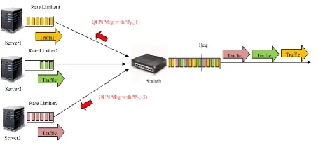
Fig. 5: FQCN system model
3.4.2 Per Flow Congestion Parameter Calculation
If the calculated congestion feedback value using Eq. (1) is negative, the congestion notification message will be sent back to all identified overrated flows through multi casting.
message to the source of the overrated flow is calculated as follows:
From the above equation, we can see that the quantized congestion feedback value in each congestion notification message is proportional to and the total number of bytes received at the switch normalized by its weight coefficient while the sum of the congestion feedback values for all congestion culprits is equal to . Moreover, is also quantized to 6 bits because is quantized to 6 bits.
Fig. 5 describes the FQCN system model with three source flows. In this example, sources 1 and 3 are identified as congestion culprits, and the congestion notification message with the quantized congestion feedback values and , calculated according to Eq. (9), are fed back to sources 1 and 3, respectively.
FQCN differs from QCN as well as AF-QCN in computing the congestion feedback value. QCN does not distinguish flow dependent congestion information and feedbacks the same congestion status to the source of the randomly sampled packet, while the congestion feedback value in the congestion notification message in both AF-QCN and FQCN is flow dependent. FQCN distinguishes from QCN as well as AFQCN by sending QCN congestion notification message to the sources of all congestion culprits rather than to the source of the randomly sampled packet in QCN and AF-QCN. Thus, the switch congestion is resolved much faster with FQCN than that with QCN or AF-QCN. Moreover, the signaling overhead of FQCN is lighter than that of QCN and AF-QCN because congestion messages could also be received by low rate sources, which are not the real congestion culprits. That is, throttling low rate sources are not as effective as throttling high rate sources in mitigating congestion. AF-QCN increases the congestion control algorithm complexity with arrival rate estimation, fair share calculation, and dropping probability calculation for each flow. AF-QCN can also identify congestion culprits, but it still feeds congestion information only back to the source of the randomly sampled packet.
4.
COMPARISONS AND DISCUSSION
Some characteristics [3] of BCN, FECN, E-FECN, QCN and FQCN congestion notification algorithms are summarized in Table 1. All of them are concerned with provisioning congestion notification in DCNs. We will discuss and compare the pros and cons of these congestion notification algorithms in the following aspects.
4.1
Fairness
Research work has shown that BCN achieves only proportional fairness but not max-min fairness. With max-min fairness, the minimum data rate that a data flow achieves is maximized first; the second lowest data rate that a data flow achieves is maximized, and so on. Proportional fairness is a compromise between max-min fairness and maximum throughput scheduling algorithm. With proportional fairness, data rates are assigned inversely proportional to its anticipated resource consumption. The fairness in FECN/EFECN is ensured by the congestion detection algorithm at the switch, which advertises the same rate to all the flows passing through the switch. Similar to BCN, the feedback message is only sent to the source of the sampled packet in QCN, and therefore QCN only achieves proportional fairness rather than max-min
fairness. One drawback of QCN is the rate unfairness of different flows when sharing one bottleneck link. Such rate unfairness also degrades the TCP throughput in synchronized readings of data blocks across multiple servers. This drawback is overcome by Fair Quantized Congestion Notification (FQCN) [12], to improve fairness of multiple flows sharing one bottleneck link. The main idea of FQCN is to distinguish congestion culprits and feedback the global and per-flow congestion information to all culprits when the switch is congested.
4.2
Feedback Control
From the system models shown in Figure, it is obvious that BCN, QCN and FQCN use backward feedback control, FECN employs forward feedback, and the forward feedback control in EFECN works together with BCN00 messages to inform the source with congestion at the switch.
4.3
Overhead
The overhead of BCN is high and unpredictable. The overhead of QCN is also unpredictable, but smaller than that of BCN since there is only negative QCN message to reduce the sending rate, and the sampling probability is proportional to the congestion indicator. The overhead of FECN is low and predictable because the FECN message is sent periodically with a small payload of about 20 bytes. The overhead of EFECN is larger than that of FECN due to the BCN00 signal involved in the EFECN algorithm.The overhead of FQCN is medium and unpredictable but smaller than that of QCN in multiple flows sharing one bottleneck link
4.4
Rate of Convergence to Fair State
BCN is slow in convergence to the fair state because AIMD-like algorithms can achieve fairness only in the long term sense. FECN and E-FECN can reach the perfect fair state within a few round trip times because all sources get the same feedback.4.5
Congestion Regulation
The source rate in BCN, QCN and FQCN can be reduced more quickly than that in FECN because the message in BCN and QCN is sent directly from the congestion point while the probe message in FECN has to take a round trip before it returns back to the source. The congestion adjustment speed is improved in E-FECN by using the BCN00 message under severe congestion.
4.6
Throughput Oscillation
BCN incurs large oscillations in throughput. FECN and E-FECN do not incur large oscillations in source throughput. The throughput oscillation is improved in QCN and FQCN with the rate increase determined jointly by Byte Counter and Rate Increase Timer at the source.
4.7
Load Sensor
BCN, QCN and FQCN send the queue dynamics back to the sources, while FECN uses a rate based load sensor to detect congestion. In addition to the rate-based sensors, queue monitor is also employed for severe congestion notification in EFECN.
4.8
Link Disconnection
a probe timeout is introduced in FECN to let the sources lower their sending rates during the link disconnection.
4.9
Fast Start
In BCN, QCN and FQCN, the sources are initialized with the full rate and ramp down if a negative feedback is received from a switch. In FECN, the sources start at a low rate and move to the equilibrium rates as successive probes return.
4.10
Number of Rate Regulators
FECN requires as many regulators as the number of concurrent flows. Owing to the introduced BCN00 message under severe congestion, the number of rate regulators in EFECN varies. In BCN, QCN and FQCN, the feedback message is only sent to the source of the sampled packet, and
therefore the number of rate regulators in BCN, QCN and FQCN also varies.
[image:6.595.62.528.239.514.2]4.11
Reactive and Proactive Signaling
BCN, QCN and FQCN use reactive signaling, FECN deploys proactive signaling, and E-FECN employs both signaling methods. Since proactive probes are only sent periodically, at least one periodic interval is needed to respond to the sudden overload, which may cause the network to be severely congested. Reactive signaling with feedback can help reduce congestion with sudden change of the link capacity or traffic patterns. However, the problem of reactive signaling is that the rates of some flows are reduced too much that they may not recover.Table 1: A Comparison of BCN, FECN, E-FECN, QCN AND FQCN
Parameters BCN[6] FECN[8] E-FECN[9] QCN[10] FQCN[12]
Fairness Unfair Perfect Perfect Unfair Fair
Feedback Control Backward Forward Forward with
beacon
Backward Backward
Overhead High Low Medium Medium Medium
Rate of Convergence to Stability
Slow Fast Fast Medium Medium
Congestion Regulation Fast Slow Medium Fast Fast
Throughput Oscillation Large Small Small Medium Medium
Load Sensor Queue based Rate based Rate + Queue
based
Queue based Queue based
Link Disconnection Support N/A Support Support Support
Fast Start Support N/A Support Support Support
Number of Rate Regulators Variable Fix (= number of source
flows)
Variable Variable Variable
Reactive and Proactive Signaling
Reactive Proactive Reactive & Proactive
Reactive Reactive
5.
CONCLUSION
This survey, we have reviewed most recent research activities in DCNs, with a specific emphasis on the topics of network congestion notification. We have summarized and compared the pros and cons of the major congestion notification algorithms proposed for DCNs.
Until now, there is no any single algorithm that can resolve every problems of congestion control on computer networks.
This paper will useful for making overall view of congestion control algorithm.
6.
ACKNOWLEDGMENTS
We express our profound gratitude to Dr. P. S. Adwani, Principal, Government College of Engineering, Aurangabad. We express our deep felt gratitude to Prof. V. P. Kshirsagar, Head of the Department, computer engineering for his constant encouragement.
7.
REFERENCES
[1] Zhang, Y. 2014. “Congestion Control, Energy Efficiency and Virtual Machine Placement for Data Centers,” pp. 1-101.
[2] Hoff, T. 2008. “Google Architecture,” http://highscalability.com/google-architecture.
[3] Zhang, Y. and Ansari, N. 2013. “On Architecture Design, Congestion Notification, Centers TCP Incast and Power Consumption in Data,” ieee communications surveys & tutorials, vol. 15, no. 1, pp. 39-64.
[4] “Address resolution for massive numbers of hosts in the data center (armd),” http://datatracker.ietf.org/wg/armd/.
[5] “Data Center Bridging Task Group,” http://www.ieee802.org/1/pages/dcbridges.html.
[6] Bergamasco, D. and Pan, R. 2005. “Backward Congestion Notification Version 2.0,” in IEEE 802.1 Meeting.
[8] Jiang, J., Jain, R. and So-In, C. 2008 “An Explicit Rate Control Framework for Lossless Ethernet Operation,” in Proc. ICC, Beijing, China.
[9] So-In, C., Jain, R. and Jiang, J. 2008 “Enhanced Forward Explicit Congestion Notification (E-FECN) Scheme for Datacenter Ethernet Networks,” in Proc. Symposium on Performance Evaluation of Computer and Telecommunication Systems, Edinburgh, UK.
[10] Alizadeh, M., Atikoglu, B., Kabbani, A., Lakshmikantha, A., Pan, R., Prabhakar, B. and Seaman, M. 2008 “Data Center Transport Mechanisms: Congestion Control Theory and IEEE Standardization,” in Proc. 46th
Annual
Allerton Conference on Communication, Control, and Computing, Allerton House, UIUC, Illinois.
[11] Kabbani, A., Alizadeh, M., Yasuda y, M., Pan, R. and Prabhakar, B. 2010”AF-QCN: Approximate Fairness with Quantized Congestion Notification for Multi-tenanted Data Centers,” in Proc. 2010 Symposium on High Performance Interconnects.
![Table 1: A Comparison of BCN, FECN, E-FECN, QCN AND FQCN BCN[6] FECN[8] E-FECN[9] QCN[10]](https://thumb-us.123doks.com/thumbv2/123dok_us/8027365.767751/6.595.62.528.239.514/table-comparison-bcn-fecn-fecn-fqcn-fecn-fecn.webp)
