(12)
United States Patent
Kolosov
et al.
(54) MECHANICAL RESONATOR
(75) Inventors: Oleg Kolosov, San Jose, CA (US); Leonid Matsiev, San Jose, CA (US); David Padowitz, Mountain View, CA (US)
(73) Assignee: Symyx Technologies, Inc., Santa Clara, CA (US)
( *) Notice: Subject to any disclaimer, the tenn of this patent is extended or adjusted under 35 U.S.C. 154(b) by 101 days.
(21) Appl. No.: 10/804,446 (22) Filed: Mar. 19, 2004
(65) Prior Publication Data
US 2004/0244487 Al Dec. 9, 2004 Related U.S. Application Data
(60) Provisional application No. 60/456,767, filed on Mar. 21,2003.
(51) Int. CI.
GOIN 291036 (2006.01) GOIN 9110 (2006.01)
(52) U.S. CI ... 73124.06; 73/31.06 (58) Field of Classification Search ... None
See application file for complete search history.
(56) References Cited
U.S. PATENT DOCUMENTS
3,273,377 A 9/1966 Testerman et al.
3,622,968 A 11/1971 Silverman
3,710,275 A 111973 Tanaka et al.
3.718.032 A 2/1973 Gray
3,762,197 A 1011973 Roof et al.
3.778.757 A 12/1973 Houston
3,902,365 A 9/1975 Knauth
3.903,732 A 9/1975 Rork et al.
3,921,622 A 11/1975 Cole
12
111111
1111111111111111111111111111
1111111111111111111111111111
DE
US007210332B2
(10)
Patent
No.:
(45)Date of Patent:
US 7,210,332
B2
May 1, 2007
3,926,271 A 12/1975 Patashinck
4,103,224 A 7/1978 Taro et al.
4,145,922 A 3/1979 Estrada, Jr. et al.
4,282,499 A
*
8/1981 DeFonzo ... 333/2314,302,694 A 11!1981 Fujishima et al.
4,312,228 A 111982 Wohltjen
4,342,936 A 8/1982 Marcus et al.
(Continued)
FOREIGN PATENT DOCUMENTS
4424422 111996
(Continued) OTHER PUBLICATIONS
Fisch, M.R., et al., "Improved Acoustic Viscosimeter Technique". J.
Acoust. Soc. Am .. Sep. 1976, pp. 623-625, v. 60, No.3.
(Continued)
Primary Examiner~Hezron Williams
Assistant Examiner~Rose M. Miller
(74) Attorney, Agent, or Firm~Selmiger Powers
(57) ABSTRo\.CT
A sensor and methods for making and using the same in which a mechanical resonator is employed, comprising a resonator portion for resonating in a fluid without the substantial generation of acoustic waves; and an electrical cOlmection between the resonator portion for oscillating and a source of an input signal; wherein the portion for resonat-ing, the electrical cOlmection or both includes a base mate-rial and a perfomlance-tuning matemate-rial that is different from the base material.
26 Claims, 7 Drawing Sheets
US 7,210,332 B2
2U.S. PATENT DOCUMENTS 5,653,939 A 8/1997 Hollis et al.
5,661,233 A 8/1997 Spates et al.
4,349,881 A 9/1982 November et al. 5,670,709 A 9/1997 Gallagher
4,361,026 A 1111982 Muller et al. 5,698,089 A 12/1997 Lewis et al.
4,370,662 A 111983 Hou et al. 5,705,399 A 111998 Larue
4,391,338 A 7/1983 Patashnick et al. 5,734,098 A 3/1998 Kraus et al.
4,445,066 A 4/1984 Nishiyama et al. 5,741,961 A 4/1998 Martin et al.
4,526,480 A 7/1985 Ward 5,741,962 A 4/1998 Birchak et al.
4,535,620 A 8/1985 Cunnungham 5,744,902 A 4/1998 Vig
4,543,829 A 10/1985 Lerch 5,770,038 A 6/1998 Iwama et al.
4,549,427 A 10/1985 Kolesar, Jr. 5,776,359 A 7/1998 Schultz et al.
4,596,697 A 6/1986 Ballato 5,777,210 A 7/1998 Voelker et al.
4,602,505 A 7/1986 Kanda et al. 5,789,665 A 8/1998 Voelker et al.
4,624,129 A 1111986 Haynes 5,792,938 A 8/1998 Gokhfeld
4,644,803 A 2/1987 Ward 5,798,452 A 8/1998 Martin et al.
4,696,181 A 9/1987 Rupprecht et al. 5,818,731 A 10/1998 Mittal et al.
4,721,874 A 111988 Emmert 5,827,952 A 10/1998 Mausure et al.
4,729,237 A 3/1988 Suzuki et al. 5,852,229 A 12/1998 Josse et al.
4,734,609 A 3/1988 Jasime 5,885,849 A 3/1999 Di Stephano et al.
4,741,200 A 5/1988 Harrunerle 5,889,351 A 3/1999 Okumura et al.
4,760,351 A 7/1988 Newell et al. 5,915,499 A 6/1999 Few
4,767,719 A 8/1988 Finlau 5,918,354 A
*
7/1999 Ikegami et al. ... 29/25.354,779,451 A 10/1988 Ezawa et al. 5,936,159 A
*
8/1999 Kano et al. ... 73/514.364,782,332 A 1111988 Cipris et al. 5,959,297 A 9/1999 Weinberg et al.
4,783,987 A 1111988 Hager et al. 5,985,356 A 1111999 Schultz et al.
4,802,370 A 2/1989 EerNisse et al. 6,023,961 A 2/2000 Discenzo et al.
4,802,384 A 2/1989 Schwarz et al. 6,034,775 A 3/2000 McFarlaud et al.
4,812,698 A 3/1989 Chida et al. 6,041,642 A 3/2000 Duncau
4,862,384 A 8/1989 Bujard 6,044,694 A 4/2000 Anderson et al.
4,890,480 A 111990 Young 6,126,311 A 10/2000 Schuh
4,893,496 A 111990 Bau et al. 6,151,123 A 1112000 Nielsen
4,904,978 A 2/1990 Barth et al. 6,155,098 A 12/2000 Shapiro et al.
4,910,523 A 3/1990 Huguenin et al. 6,157,449 A 12/2000 Hajduk
4,922,745 A 5/1990 Rudkin et al. 6,175,409 B1 112001 Nielsen et al.
4,970,492 A 1111990 King 6,176,323 B1 112001 Weirich et al.
5,006,845 A 4/1991 Calcar et al. 6,182,499 Bl 2/2001 McFarlaud et al.
5,179,028 A 111993 Valie et al. 6,223,589 B1 5/2001 Dickert et al.
5,191,791 A 3/1993 Gerardi et al. 6,247,354 Bl 6/2001 Vig et al.
5,201,215 A 4/1993 Graustaff et al. 6,260,407 B1 7/2001 Petro et al.
5,204,529 A 4/1993 Diatschenko 6,260,408 B1 7/2001 Vig et al.
5,224,174 A 6/1993 Schneider et al. 6,265,226 B1 7/2001 Petro et al.
5,235,844 A 8/1993 Bonne et al. 6,269,686 B1 8/2001 Halm et al.
5,253,530 A 10/1993 Letcher, III 6,275,137 B1 8/2001 Doppalapudi et al.
5,283,037 A 2/1994 Baer et al. 6,286,363 B1 9/2001 Discenzo
5,296,374 A 3/1994 Culshaw et al. 6,294,388 B1 9/2001 Petro et al.
5,306,644 A 4/1994 Myerholtz et al. 6,296,771 B1 10/2001 Miroslav
5,325,704 A 7/1994 Mariami et al. 6,306,358 B1 10/2001 Yamamoto
5,332,961 A 7/1994 Harrunerle 6,311,549 B1 1112001 Thundat et al.
5,334,900 A 8/1994 Kawashima 6,327,890 Bl 12/2001 Galipeau et al.
5,338,416 A 8/1994 Mlcak et al. 6,336,353 B2 112002 Matsiev et al.
5,357,964 A 10/1994 Spivey et al. 6,371,640 B1 4/2002 Hajduk
5,361,632 A 1111994 Magnaui 6,393,895 B1 5/2002 Matsiev et al.
5,375,470 A 12/1994 Matsushima et al. 6,401,519 Bl 6/2002 McFarlaud et al.
5,421,190 A 6/1995 Braudle et al. 6,407,479 B1 6/2002 Moellendorf et al.
5,434,650 A 7/1995 Nakahara et al. 6,412,131 Bl 7/2002 Zhao et al.
5,435,170 A 7/1995 Voelker et al. 6,441,716 B1 8/2002 Doppalapudi et al.
5,438,231 A
*
8/1995 Khoshnevisau et al . .... 310/321 6,456,096 B1 9/2002 Ericson et al.5,445,008 A 8/1995 Wachter et al. 6,459,995 B1 10/2002 Collister
5,454,045 A 9/1995 Perkins et al. 6,494,079 B1 12/2002 Matsiev et al.
5,455,475 A 10/1995 Josse et al. 6,507,945 B1
*
112003 Rust et al. ... 717/1035,464,509 A 1111995 Mlcak et al. 6,509,749 B1 112003 Buelna et al.
5,469,369 A 1111995 Rose-Pehrsson et al. 6,511,915 B2 112003 Mlcak
5,477,726 A 12/1995 Stabinger et al. 6,519,034 Bl 2/2003 Engler et al.
5,488,866 A 2/1996 Ravel et al. 6,535,001 B1 3/2003 Waug
5,524,477 A 6/1996 Wajid 6,536,634 B2 3/2003 Berndorfer et al.
5,524,636 A 6/1996 Sarvazyau et al. 6,545,392 B2 4/2003 Kawauchi et al.
5,528,924 A 6/1996 Wajid et al. 6,557,396 B2 5/2003 Ismail et al.
5,531,091 A 7/1996 Gademann et al. 6,557,419 B1
*
5/2003 Herb et al. .. ... 7317665,533,402 A 7/1996 Sarvazyau et al. 6,564,126 B1 5/2003 Lin et al.
5,571.401 A 1111996 Lewis et al. 6,626,025 B2 9/2003 Potyrailo et al.
5,571,952 A 1111996 Kauzlarich 6,640,644 Bl 1112003 Mireles et al.
5,604,441 A 2/1997 Freese et al. 6,644,095 B2 1112003 Vau Mullekom et al.
6,661,162 Bl 12/2003
6,664,067 Bl 12/2003 6,928,877 B2 8/2005 6,936,837 B2 * 8/2005 200110010174 Al 8/2001 2002/0064649 Al 5/2002 2002/0068488 Al 6/2002
2002/0070841 Al 6/2002 2002/0074897 Al 6/2002
2002/0092340 Al 7/2002 2002/0113596 Al 8/2002
2002/0121132 Al 9/2002 2002/0137348 Al 9/2002
2002/0148529 Al 10/2002 2002/0162385 Al 1112002 2002/0162390 Al 1112002 2002/0178787 Al 12/2002
2002/0178805 Al 12/2002
2002/0190814 Al * 12/2002 2002/0194906 Al 12/2002
2003/0000291 Al 112003 2003/0041653 Al 3/2003 2003/0041659 Al 3/2003 2003/0062910 Al 4/2003
2003/0083825 Al 5/2003 2003/0116497 Al 6/2003
2003/0118078 Al 6/2003 2003/0119060 Al 6/2003
2003/0124028 Al 7/2003 2003/0145647 Al 8/2003
2003/0179002 Al 9/2003
2003/0213292 Al 1112003 2003/0222656 Al 12/2003
Nagai et al. Hajduk et al. Carlson et al.
US 7,210,332 B2
3
WO WO
WO 03/054482 WO 2004/036191
7/2003
4/2004
Yarnada et al. ... 257/2
OTHER PUBLICATIONS
Matsiev et al. Lembke et al. Tuller et al. Doppalapudi et al. Ma et al. Prater et al. Horie et al. Breed et al. Mlcak Berndorfer et al. Ismail et al. Ismail et al. Matsiev et al. DiFoggio et al.
Yamada et al. ... 333/187 Goodwin et al.
Kolosov et al. Matsiev et al. Marszalek et al. Wang et al. Berndorfer Carlson et al. Carlson et al. Desrosiers et al. Carlson et al. Ismail et al. Beylich et al. Budeiri et al. Phillips et al.
Kanazawa, K. Keiji and Joseph G. Gordon II, "The Oscillation Frequency of a Quartz Resonator in Contact with a Liquid", Analytica Chimica Acta, 1985, pp. 99-105, Elsevier Science Pub-lishers B.
v., Amsterdam.
Kipling, Arlin L and Michael Thompson, "Network Analysis Method Applied to Liquid-Phase Acoustic Wave Sensors", Anal. Chem., 1990, pp. 1514-1519,62.
Michels, A. et aI., "1 MHz Quartz Length Extension Resonator as a Probe for Scanning Near-Field Acoustic Microscopy", Thin Solid Films, 1995, pp. 172-175,264.
M\U'amatsu, Hiroshi et aI., "Computation of Equivalent Circuit Paranleters of Quartz Crystals in Contact with Liquids and Study of Liquid Properties", Anal. Chem., 1988, pp. 2142-2146, 60. M\U'amatsu, H. et al., "A Quartz Crystal Viscosity Sensor for Monitoring Coagulation Reaction and Its Application to a Multichannel Coagulation Detector", Biosensors & Bioelectronics, 199 L pp. 353-358, 6, Elsevier Science Publishers Ltd. England. Newsam, J. et al., "High Throughput Experimentation for the Synthesis of New Crystalline Microporous Solids," Microporous and Mesoporous Materials 48 (2001) 355-365.
Akporiaye, D. et aI., "Combinatorial Chemistry-The Emperor's New Clothes?," Microporous and Mesoporous Materials 48 (2001) 367-373.
Hauptmann et aI., Ultrasonic Sensors for Process Monitoring and Chemical Analysis; State-of-the-Art and Trends, 1998, pp. 32-48. Jakoby et aI., Viscosity Sensing Using a Love-wave Device, 1998, pp. 275-281.
FOREIGN PATENT DOCUMENTS
Polla et aI., Processing and Characterization of Piezoelectric Mate-rials and Integration into Microe1ectromechanical Systems, 1998, pp. 563-597.
DE 10014724 Al EP 0102490 Bl EP
o
282 251 Bl EP 0282251 EP 0317356 Bl EP 0676638 EP 0769695 A EP 0779510 EP 0813236 GB 1385488 GB 2114745 GB 2187286 JP 57124236 JP 59126931 JP 60134617 JP 05129874 JP 08112613 A JP 11094726 WO WO 91102975 WO WO 95/13278 WO WO 98/01739WO WO 98/15501
WO WO 98/37412
WO WO 99/18431
WO WO 99/51980
WO WO 00/58709
WO WO 00/67086
WO WO 01177624
WO WO 01177624 A2 WO WO 02/12265 WO WO 02/16888 WO WO 02/23134
WO WO 02/077613
WO WO 02/093136 Al WO WO 02/093740 Al
*
WO WO 03/014732 WO WO 03/1003909/2001 3/1984 3/1988 9/1988 5/1989 10/1995 4/1997 6/1997 12/1997 8/1971 8/1983 9/1987 8/1982 7/1984 7/1985 5/1993 5/1996 9/1997 3/1991 5/1995 611997 411998 811998 4/1999 10/1999 312000 11/2000 10/2001 10/2001 212002 212002 3/2002 10/2002 1112002 11/2002 212003 412003
Pujari et aI., Reliable Ceramics for Advanced Heat Engines, Ameri-can Ceramic Society Bulletin, vo!' 74, No.4, Apr. 1995, pp. 86-90. Manalis et aI., Two-dimensional Micromechanical Bimorph Arrays for Detection of Thermal Radiation, App!. Phys. Lett., vol. 70, No. 24, Jun. 16, 1997, pp. 3311-3313.
Lin et al., Operation of an Ultrasensitive 30-MHz Quartz Clystal Microbalance in Liquids, Analytical Chemistry, Vo. 65, No. 11, Jun. 1, 1993, pp. 1546-1551.
Li et aI., Electromechanical Behavior of PZT-Brass Unimorphs, Jo\U'nal of the American Ceramic Society, vol. 82, No.7, 1999, pp. 1733-1740.
Cleland et al., Fabrication of High Frequency Nonometer Scale Mechanical Resonators from Bulk Si Crystals, Appl. Phys. Lett" vol. 69, No. 18, Oct. 28, 1996, pp. 2653-2655.
U.S. Appl. No. 09/420,334 entitled "Graphic Design of Comb ina to-rial Mateto-rial Libraries" (Lacy, et al.) filed on Oct. 18, 1999. U.S. Appl. No. 09/550,549 entitled "Automated Process Control And Data Management System And Methods" (Crevier, et al.) filed on Apr. 14, 2000.
U.S. Appl. No. 09/285,963 entitled "Rapid Characterization of Polymers" (Safir et al.) filed on Apr. 2, 1999.
Matsiev, "Application of Flex\U'al Mechanical Resonators to Simul-taneous Meas\U'ements of Liquid Density and Viscosity", 1999 IEEE UltraSonics Symposium, pp. 457-460.
Nesbitt W. Hagood IV et aI., "Development of Micro-Hydraulic Transducer Technology", 10th International Conference on Adap-tive Stmctures and Technologies, Oct. 11-13, 1999, Paris, France. Hoenk, Michael, et al .. , "Surface Acoustic Wave Hygrometer: Measuring Water Vapor in Earth's Atmosphere," http://mishkinjpl. nasa.gov, accessed Mar. 16, 2002, 7 pages.
Trolier, Susan et aI., "Preparation of Chemically Etched Piezoelec-tric Resonators for Density Meters and Viscometers", Mat. Res. Bull., vol. 22, pp. 1287-1274 (1987).
US 7,210,332 B2
4
H. Endo, K. Soda, r. Kambe, H. Muramatsu, "Online Monitoring of the Viscosity in Dextran Fermentation Using Piezoelectric Quartz Crystal", Biotechnology and Bioengineering, vol. 36, S 636-641 (1990).
Mason, W. P., Hill M., "Measurment of the Viscosity and Shear Elasticity of Liquids by Means of a Torsionally Vibrating Crystal", Transactions of A.S.M.E., 69 (1947) 359-370.
Barnes
c.,
"An in vitro urea sensor using a torsion-wave crystal device", Sensors and Actuators B, 8 (1992) 143-149.Schmitt N. et aI., "A new method based on acoustic impedance measurements for quartz immunosensors", Sensors and Actuators B43 (1997) 217-233.
Benes et aI., "Viscosity Sensor Based on a Symmetric Dual Quartz Thickness Shear Resonator", pp. 1-7. 2003.
NSF Award Abstract #0239151, Feb. 6, 2003, pp. 1-2.
Nussbaum, "An Accurate Non-Radioactive Fluid Density Sensor", presentation to the Society of Petroleum Engineers, Bergen, Nor-way, Apr. 1, 2003.
Lec et aI., "A Remote Acoustic Engine Oil Quality Sensor", 1997 IEEE UltraSonics Symposium, pp. 419-422.
Zhang et ai, "Contributions of Amplitude Measurement in QCM Sensors", IEEE Transactions on Ultrasonics, Ferroelectrics, and Frequency Control, vol. 43, No.5, Sep. 1996, pp. 942-947. Smith et aI., Water Sorption Isotherms and Enthalpies of Water SOlption by Lysozyme Using the Quartz Crystal Microbalance/heat Conduction Calorimeter, Biochimica et Biophysica Acta, Oct. 4, 2001, pp. 150-159.
Zhang et al.: "Determination of Liquid density with a low frequency mechanical sensor based on quartz tuning fork" Sensors and Auctuators B, Elsevier Sequoia S.A. Lausanne, CH. vol. 84, No. 2-3, May 15, 2002, pp. 123-128.
Shih et al.: Simultaneous Liquid Viscosity and Density Determina-tion with Piezoelectric Unimorph Cantilevers: Journal of Applied Physics, American Institute of Physics. New York, U.S., vol. 89, No. 2, Jan. 15,2001, pp. 1497-1505.
Dring et al.: "Integrated on-line multi sensing of fluid flow using a mechanical resonator" Sensors and Actuators A, Elsevier Sequoia SA, Lausanne, CH, vol. 85, No. 1-3, Aug. 25, 2000, pp. 275-279. Greenwood et aI., "Measurement of Viscosity and Shear Wave Velocity of a Liquid or Slurry for On-line Process Control", Ultrasonics 39 (2002) pp. 623-630.
Langdon, "Vibratory Process Control Transducers", The Marconi Review, Third Quarter, 1980, pp. 156-175.
A&D Weighing, SV Series User's Handbook Vl.04E, p. 1-40, date unknown.
"@Kavlico Our Sensors Are the Solution!", Kavlico, A Solectron Company, Capability Product Brochure-Industrial Sen-sors and Tranducers, date unknown.
"Automotive Engineering International Online: Top 50 Products for 1999", Product Info. List/Oil Quality Sensor, 1999, www.sae.org/ automag/top50prod/17.htm, printed Feb. 5, 2004, p. 17. Bohmer, Elemente der angewandten Elektrotechnik, p. 74-79, 1992, Translation attached.
"diScentris Cantilever Sensor Research Tool for Science and Indus-try", Veeco Instmments Inc. Brochure, 2003.
"CN-5000 Vibro Viscometer Utilizing Tuning-Fork Technology", A&D Medical Weighing Test & Measurement Digital Testing and Measurement Products, Jan. 28, 2000, Yahoo Search printed Jun. 18, 2003.
"Field Trials of the Viscosity & Fluid Density Tool", Nan Gall Technology News Releases, Aug. 2002, www.nangall.cOlnlprod-ucts/pltlFluid_Density_Tuned.htm, printed Feb. 14,2003. "EPSON presents in MC-30A: Reliable 32.768Hz Dedicated to Automotive Applications", Aug. 25, 2003, Electronic Devices Press Release, w\vw.epson.com.sq.ntml. body_ed_press_25_aug ... .2003.html, printed Feb. 11,2004. Ferry, John D., "Viscoelastic Properties of Polymers", 1980, Chap-ters 5-8, p. 96-176, John Wiley & Sons, Inc.
Fleming, "The Vibrating Tuning Fork Fluid Density Tool", p. HI-Hl5, Nan Gall Technology Ltd, Aberdeen, Smith Institute, date unknown.
Fleming, "Theory of the vibrating tuning fork fluid density tool", Mar. 15, 2002, www.lancs.ac.ukdepts!physics/conf/esgi!NanGall/ transducer.htm, printed May 7, 2003.
Fleming, "A Vibrating Tuning Fork Fluid Density Tool", Smith Institute Projects, last updated Jul. 15, 2002, www.smithinst.ac.uk! projects!NanGallESGI2002, printed Feb. 5, 2004.
Godemann, Ralph, "Refrigerant Flow in Evaporators", Heatcraft North America Transfer OEM Products Brochure, 2000, www. heatcraftoem.comiTechTopics/refrigeranLflow.htm.
Grate, et al. "Sm31t Sensor for Trace OrganophospholUs and Organosulfur Vapor Detection Employing a Temperature-Con-trolled Array of Surface Acoustic Wave Sensors, Automated Sample Preconcentration, and Pattern Recognition", Analytical Chemistry, 1993, p. 1868-1881, vol. 65, No. 14.
Greenwood, Margaret, et aI., "On line Sensor for Density and Viscosity Measurements of a Liquid or Slurry for Process Control in the Food IndustJy", Presented at Sensors and ContJ'ol in Food Processing, Sixth Conference on Food Engineering, AIChE Annual Meeting, 1999, abstract.
Hanrrnond, 1M. et ai, "An Acoustic Automotive Engine Oil Quality Sensor*", Transducers '97,1997 International Conference on Solid-State Sensors and Actuators, Chicago, Jun. 16-19, 1997, p. 1343-1346.
Hammond, 1.M. et al, "A.n Acoustic Automotive Engine Oil Quality Sensor", IEEE International Frequency Control Symposium, 1997, p. 72-80.
Hlavay,1. et aI., "Applications of the Piezoelectric Clystal Detector in Analytical Chemistry". Analytical Chemistry, 1977, p. 1890-1898, vol. 49, No. 13.
Karrai, "Lecture Notes on Shear and Friction Force Detection with Quartz Tuning Forks", Presented at the "Ecole Thematique du CNRS" on near-field optics, Mar. 2000, La Londe les Maures, France, p. 1-23.
Laine, E., et aI., "Device for the Investigation of the Humidity-Related Behaviours of Materials", 1986, Department of Physics, University of Turku, Finland.
Landau, L.D., et al., "Fluid Mechanics", "Viscous Fluids; Oscilla-tory Motion in a Viscous Fluid", 1959, p. 96-97, Perg31Ilon Press Ltd.
"The Lubri-Sensor Electronic Oil Quality Analyser", www. pmlubricants.com.au/pm_lube_conceptilubri-sensor.htm, Eco Oil Pty. Ltd., Copyright 1997-2004, printed Feb. 5, 2004, p. 1-2. Matsiev, L.F., "Application of Flexural Mechanical Resonators to High Throughput Liquid Characterization" 2000 IEEE International Ultrasonic Symposium, San Juan, Puerto Rico (Oct. 22-25, 2000), p.427-434.
Merhaut, Josef, "Theory of Electroacoustics", "Theory of Mechani-cal Systems with Distributed Elements", 1981, p. 100-101, McGraww-Hill International Book Company.
Mur31Ilatsu, et aI., "Viscosity Monitoring with a Piezoelectric Quartz Crystal and its Application to Determination of Endotoxin by Gelatin of Limulus Amebocyte Lysate", Analytica Chimica Acta, 1988, p. 91-98, 215, 1988 Elsevier Science Publishers BV Nomura, et al., "Electrolytic Determination of Nanomolar Concen-tJ'ations of Silver in Solution with a Piezoelectric QU31tz Clystal", Analytica Chimica Acta, 1981, p. 97-102, 131, Elsevier Scientific Publishing Company.
Oden, P.r., et aI., "Viscous drag measurements utilizing microfabricated cantilevers", Applied Physics Letters, Jun. 24, 1996, p. 3814-3816, 68(26).
Puuman, "Hygroscopicity Measurement Apparatus", date unknown, http://web.archive.org/web/20010405220058!wvv.w.puuman.coml hma.ht111.
"Sensors", Actuators Components Sensors Applications Process Technology System Integration Deutsch, Fraunhofer Verbund Mikroelektronik, 2001, www.izm.fhg.delvue/ seiteniseiten_neulenglish/sensoren_e.html, printed Oct. 3, 2002. "Sensors at Actuators Intellek Oil Condition Sensor", Delphi Cor-poration, www.delphi.com. date unknown.
US 7,210,332 B2
5"SOS Smart Oil Sensor", Impact Technologies LLC Brochure, 2003.
Surface Acoustic Wave (SAW) Hygrometer (Micro Weather Sta-tion), last updated Feb. 14, 2001, http://technology.ip!.nasa.gov/ gaUery/gl_pages/saw.html.
Wright, Dr. Robert, et a!., "Sensor Technology Improves Jet Engine Reliability", printed Feb. 5, 2004, www.afrlhorizons.comiBriefs/ JuneOllPR0003.html, p. 1-2.
Wullner, D., et a!. "Multi-Function Microsensor for Oil Condition Monitoring Systems", AMAA Paper 030305b, 2003, p. 1-5. "ViscoMaster HFO Viscosity Transmitter for Marine and Power Applications", Solartron Mobrey Brochure, Jan. 2002.
Zeisel et ai, "A Precise and Robust Quartz Sensor Based on Tuning Fork Technology for (SF 6)-gas density control", Sensors and Actua-tors (2000) p. 233-236, voL 80.
Viscosity and Density Sensing with Ultrasonic Plate Waves, B.A. Martin, S.W. Wenzel, and R.M. White, Sensors and Actuaturs, A21-A23 (1990), 704-708.
"Micromachined viscosity sensor for real-time polymerization monitoring", O.Brand, IM. English, SA Bidstmp, M.G. Allen, Transducers '97, 121-124 (1997).
"Frequency response of cantilever beams immersed in viscous fluids with applications to the atomic force microscope", IE. Sader, lApp!. Phys. 84, 64-76 (1998).
"Resonance response of scanning force microscopy cantilever", G.Y. Chen, R.I. Warmack, T.Thundat, and D.P. Allison, Rev. Sci. InstnuTI. 65, 2532-2537(1994).
"Lecture notes on shear and friction force detection with quartz tuning forks" Work presented at the "Ecole Thematique du CNRS" on near-field optics, Mar. 2000, La Londe les Msures, France by Khaled Karrai, Center for.
I Sorab, G.S. Saloka: "Engine Oil Viscosity Swnsors Using Disks of PZT Ceramic as Electromechanical Vibrators" Society of Auto-motive Engineers SAE, No. 971702, 1997.
u.s.
Patent
May 1, 2007
Sheet 1 of 7
US 7,210,332 B2
12
lFig-1
22
18
r-..
/ / ,Jf-. , ... ,' , ... -•• , ... ,. ,..,.,." ... ,' ... , , ... , ... , ... , ... , ... ,. , ... , ... ,. ,.,.,.., •• - , ,.,..,.., ••
~.
I"~
~--// 18 ~--//
J - - - r/
, ' ,
/
'
I,'
r--.J....-... _ _
.-J,
t----'----_
_ _ _ + _ _ _ "u.s.
Patent
May 1, 2007
Sheet 2 of 7
US 7,210,332
B2
FIG. 3
14
[image:7.595.103.493.346.603.2]u.s.
Patent
May 1, 2007
Sheet 3 of 7
US 7,210,332
B2
FIG. 4
14
FIG. 5
[image:8.595.98.493.126.713.2]u.s.
Patent
May 1, 2007
Sheet 4 of 7
US 7,210,332
B2
FIG.
6
14
FIG. 7
18
[image:9.595.96.488.75.774.2]u.s.
Patent
May 1, 2007
Sheet 5 of 7
US 7,210,332
B2
FIG. 8
14
12
18
FIG. 9
[image:10.595.101.496.168.749.2]u.s.
Patent
May 1, 2007
Sheet 6 of 7
US 7,210,332 B2
FIG. 10
14
12
18
FIG. 11
16
[image:11.595.104.496.173.737.2]u.s.
Patent
May 1, 2007
Sheet 7 of 7
US 7,210,332
B2
FIG. 12
16
/
10
14
16
[image:12.595.101.493.328.602.2]US 7,210,332 B2
1
MECHANICAL RESONATOR
CLAIM OF PRIORITY
This application claims the benefit of u.s. Provisional Application No. 60/456,767 filed on Mar. 21, 2003.
TECHNICAL FIELD
2
a mechanical resonator (and most preferably a tuning fork resonator) in which materials alternative or in addition to quartz crystals are employed.
In another aspect of the present invention, a highly preferred configuration for a ttIDing fork for use in a sensor is employed, pursuant to which the shape of the tuning fork is generally that of an "H" or a modified "H".
In one preferred embodiment, the resonators according to the present invention are placed in a fluid and a signal is The present invention is directed to improvements in the
fabrication and usc of mechanical resonators for measuring various properties of fluids (including both liquids and vapors).
10 applied to the resonator. A characteristic of the fluid is determined based upon the resonator response. In one even more highly preferred embodiment, the resonators according to the present invention are placed in a fluid and a variable frequency input signal is applied to the resonator. The BACKGROUND ART 15 frequency of the signal is varied and the frequency and a characteristic of the fluid is detennined based upon the resonator response.
The use of mechanical resonators for measuring proper-ties of materials, including liquid and vapor phases, has been disclosed in commonly-owned u.s. Pat. No. 6,336,353
(Matsiev. et al.)("Method and apparatus for characterizing 20
matcrials by using a mechanical resonator"); and U.s. Pat. No. 6,182,499 (McFarland, et al.) ("Systems and methods for charactcrization of materials and combinatoriallibrarics with mechanical oscillators"); and u.s. patent application Ser. Nos. 091723,818, 09/800,819, and 09/133,171; pub- 25
Ii shed U.S. Patent Application No. 20030000291; and u.s. patent application Ser. No. 101155,207 ("High Throughput Microbalance and Methods of Using Same") (filed May 24, 2002), all of which are hereby expressly incorporated by refcrence for all purposes.
BRIEF DESCRIPTION OF THE DRAWINGS
FIG. 1 is a perspective view of one illustrative resonator in accordance with the present invention.
FIG. 2 is a perspective view of one illustrative resonator in accordance with the present invention.
FIG. 3 is a perspective view of another resonator showing a dielectric material partially covering electrodes of the resonator.
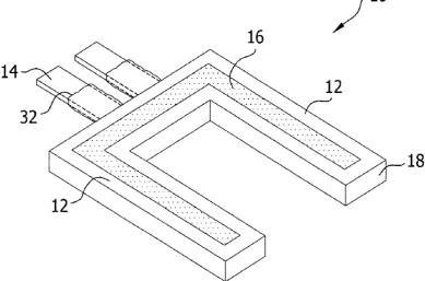
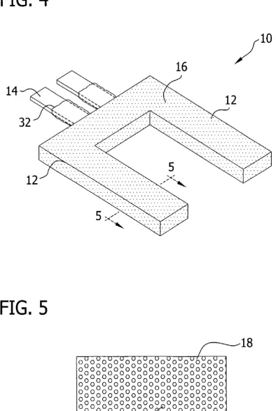
FIG. 4 is a perspective view of a resonator having a perfonnance tuning material dispersed within a base
mate-30 rial.
It has been observed that a preferred resonator is one that is opcrated at a rclatively low frcqucncy, e.g. below about 1
MHz; however, resonators may be operated at higher fre-quencies. For example, a highly preferred resonator is one that employs at least one cantilever end, and more preferably 35
a plurality of cantilever ends, such as would be fmIDd in a tuning fork.
FIG. 5 is a cross section through a tine of the resonator shown in FIG. 4.
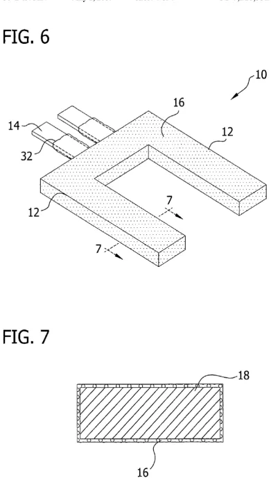
FIG. 6 is a perspective view of a resonator having a perfonnance tuning material including a layer entirely over-lying a base material.
FIG. 7 is a cross section through a tine of the resonator shown in FIG. 6.
The above patent documents disclose the employment of various alternative resonators, such as tridents, cantilevers, torsion bars, bimorphs, or membrane resonators.
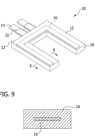
FIG. 8 is a perspective view of a resonator having a perfonnance tuning layer that is an intermediate layer in the
40 base material. The documents also address the possibility of coating
resonators with a coating for sensitivity to certain chemicals, wear resistance, for environmental protection or for some other functionality.
FIG. 9 is a cross section through a tine of the resonator shown in FIG. 8.
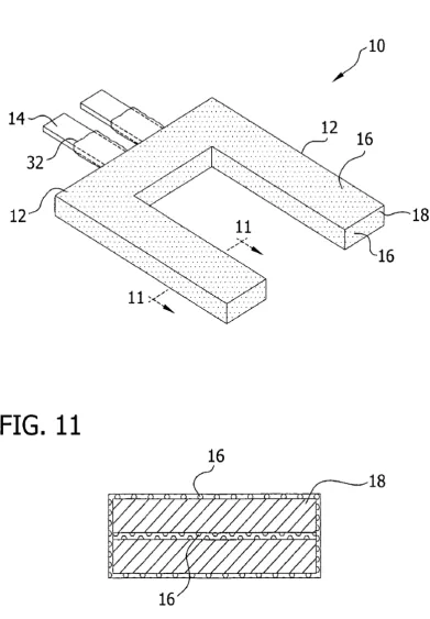
FIG. 10 is a perspective view of a resonator having a perfonnance tuning material including a layer entirely over-laying a base material and a layer that is an intermediate layer in the base material in combination.
FIG. 11 is a cross section through a tine of the resonator shown in FIG. 10.
As the success of resonators for use in sensing applica- 45
tions has grown, the cnvironmcnts within which thc reso-nators are expected to perform have likewise increased. In particular, the desire for increasing resonator life in high stress, abrasive and/or chemically aggressive enviro111nents has driven the search for improved specific material and structural combinations.
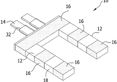
FIG. 12 is a perspective view of a resonator having
50 perfonnance tuning material that is an intermittent layer along edges of the base material.
SUMMARY OF THE INVENTION DETAILED DESCRIPTION OF THE PREFERRED EMBODIMENTS
The present invention is directed primarily to a method using a mechanical piezoelcctric rcsonator ("mechanical resonator") for measuring physical and electrical properties, such as the viscosity, the density, the viscosity density product, the impedance, the dielectric capacitance, the dielectric constant, and the conductivity of sample liquid compositions. The detailed description below focuses pri-marily on mechanical resonators, and specifically tuning fork resonators. Howcvcr, thc principles of thc invention can The present invention is directed to improvements in 55
sensing devices and systems employing mechanical resona-tors, and particularly improvements to structure and material combinations suitable especially for extreme operating con-ditions, such as encountered without limitation in harsh cnvironmcnts (c.g., oil ficlds, opcrating machinery fluids, 60
chemical processing or otherwise), or where micro-scale or cven nano-scale scnsitivity is crucial to succcssful perfor-mance (e.g., for measuring hygroscopicity, for flow injection analysis, for high throughput parallel or rapid-serial
screcn-ing or otherwise). 65 also be applied to thickness shear mode ("TSM") resonators, such as a rcsonator having a quartz crystal sandwichcd in between electrodes. Thus the present invention has applica-Accordingly, one aspect of the present invention is
US 7,210,332 B2
3
bility to resonators that are oscillated such that a portion of the structure of the resonator is passed through a fluid such as tridents, cantilevers, torsion bars, unimorphs, bimorphs, membrane resonators or combinations thereof.
The employment of any of a variety of different art-disclosed measurement systems may be made in accordance with the present invention, and the discussion of a preferred variable frequency input signal system is not intended as limiting.
Nonetheless, pursuant to a preferred variable frequency input signal system, a mechanical resonator according to the present invention is connected to a measuring system that sends a variable frequency input signal, such as a sinusoidal wave, that sweeps over a predetermined frequency range, preferably less than about 100 kHz (e.g., in the 25~30 kHz range) for a tuning fork resonator and in a higher range for the TSM resonator. The resonator response over the fre-quency range is then monitored to determine selected physi-cal and electriphysi-cal properties of the fluid. Absolute values may be obtained if desired, as may relative. comparative or index values. Additionally, it is possible also that the system of the present invention may be employed with deternlining whether a certain threshold criteria is met in the fluid being analyzed.
The hardware for the present measuring system may be any suitable hardware. It may include, for example, art-disclosed network analyzers, see, e.g., U.S. Pat. No. 6,336, 353 (Matsiev, et al.)("Method and apparatus for character-izing materials by using a mechanical resonator"); and
u.s.
Pat. No. 6,182,499 (McFarland, et al.) and publishedu.s.
Patent Application No. 20030000291, hereby incorporated by reference. The hardware might also be part of an appli-cation specific integrated circuit (ASIC), such as is disclosed for example in commonly owned, co-pending application entitled "Integrated measurement assembly for a machine fluid sensing system" (U.S. patent application Ser. No.10/452,264), hereby incorporated by reference, as disclosed
4
operators to extend the duration between fluid service events, while helping to assure continued operational integ-rity of a machine.
Any dynamic assembly that depends on fluids to operate (e.g., where friction and heat are of a concern), will benefit from hardware capable sensing the state of a fluid. For instance, the ability to dynamically monitor fluid condition, process data obtained from the monitoring, and report char-acteristics of the fluid to an interface or operator can have
10 many applications. Assemblies that may benefit from the defined embodiments of the present invention are many, and can include without limitation, engines in general, automo-biles, heavy machinery, military equipment, airplane parts, oil drilling, exploration and production well logging, oil
15 refining, pipeline and quality control applications, marine
transportation, sub-sea exploration and aerospace related equipment, or any other fluid containing application. In addition, contemplated methods include a step of assem-bling the hardware into a device that is incorporated into
20 engines in general, automobiles, heavy machinery, military equipment, airplanes, oil drilling, exploration and produc-tion well logging equipment, oil refining, pipeline and quality control equipment, marine transportation equipment, sub-sea exploration and aerospace related equipment, or any
25 other equipment that utilizes fluids for operations. In the automotive field, numerous components require lubrication, which is not limited to engine oil. For example, other automotive components may include the transmission, the transfer case, the differential, etc. Still fhrther, the
30 sensing system may fhrther be used to determined the quality and amount of other fluids which are not necessarily used predominantly as a lubricant, including: brake fluids, steering fluids, antifreeze fluids, refrigerant fluids, wind-shield washer fluids, or any other fluid located in an
auto-35 motive system.
In one embodiment of suitable hardware, an oil sensing system is used to detennine the component characteristics and amount of engine oil. In an automotive application, the
40 oil sensing system will provide a user. at a minimum, with a warning as to the need to change the oil (such as owing to the presence of contaminants, a breakdown or loss of useful ingredients or otherwise). In such an application, the warn-ing is essentially informwarn-ing the user of the automobile that in connllonly owned, co-pending application entitled
"Application specific integrated circuitry for controlling analysis of a fluid" (PCT/US04/08555), claiming benefit of U.S. provisional application No. 60/419,404), hereby incor-porated by reference, as disclosed in co-owned, co-pending application entitled "Resonator Sensor Assembly" (l0/804,
379, PCTlUS05/08531 and PCTIUS04/08522, claiming
benefit of U.S. provisional 60/456,517), as disclosed in co-owned, co-pending application entitled "Environmental Control System Fluid Sensing System And Method" (Inter-national patent application no. US03/32983) or as disclosed 50
in co-owned, co-pending application entitled "Mechanical Resonators" (PCTIUS04/08526, claiming benefit of U.S. provisional application No. 60/452,292). All of the forego-ing are hereby incorporated by reference.
45 the engine oil has reaches a quality level or condition that is lower than that recommend by the automobile's manufac-turer (or set by the oil manufacmanufac-turer ).
The fluid sensing system preferably uses a mechanical resonator as the fluid sensor in accordance with the present invention. The mechanical resonator is at least partially contained in the fluid under-test. To monitor the condition of the fluid under-test (i.e., engine oil), the mechanical reso-nator is provided with electrical energy through a frequency generator. The frequency generator is designed to apply a
55 frequency signal (to the mechanical resonator) that is swept
over a predetennined frequency range. Electronics are then used to detect the response signal from the mechanical resonator and process the signal to ascertain characteristics of the fluid under-test. In an embodiment of the fluid sensing Generally, the hardware for measuring system provides a
versatile fluid sensing system. More specifically, the hard-ware provides a fluid sensing system for machines that rely upon the presence, condition or both of a fluid to maintain efficient operation, such as (without limitation) a synthetic or natural engine oil. In an automotive application, the user is provided with the ability to determine the actual condition (e.g. or the relative deviation of the state of the engine oil from its initial or virgin state) of the engine oil at any particular time, including during operation. Alternatively, in conjunction with assessing fluid condition, the hardware 65
may also detennine the amount of fluid remaining in a reserve of an assembly. This advantageously allows machine
60 system, the electronics are provided in the form of an
application specific integrated circuit (ASIC). In addition, the hardware might also be part of or include a field programmable gate array (FPGA).
US 7,210,332 B2
5
in connnonly owned, co-pending application entitled "Reso-nator sensor assembly and method" (60/456,517).
The packaging for the present sensor provides a protective mounting structure for the sensor and other associated components during installation and use; the sensor may advantageously be incorporated on to a platform to fonn a sensor package. Such a configuration would allow the sensor to be in contact with a fluid while protecting associated components from the harsh enviroll111ent typically found in dynamic systems and any abuse associated with the instal- 10
lation of the same. In a preferred arrangement, the sensor package would comprise a sensor element, having an exposed sensing surface, attached to a substrate such that the exposed sensing surface is spaced from the platfonn. Advan-tageously, the sensor package may be further configured 15
with other components to facilitate the determination of the quality of a fluid. Such components may comprise, a hous-ing, a resistance temperature sensor, an application specific integrated circuit (ASIC), and/or a conduit for connnunicat-ing with other components. As such, it may be desirable to 20
coat all or some of the additional components and a portion of the sensor with a protective coating.
In the foregoing description, numerous specific details are set forth in order to provide a thorough understanding of the fluid sensing system, hardware and packaging that may be 25
used with the present invention. It will be apparent, however, to one skilled in the art that the present invention may be practiced without some or al1 of these specific details. In other instances, well known process steps have not been described in detail in order not to unnecessarily obscure the 30
present invention.
In accordance with a preferred embodiment ofthe present invention, there is disclosed an improved material system for use as a resonator. The material system is predicated upon the substitution of all or part of a piezoelectric material 35
(e.g. quartz crystal) with a performance-tuning material that improves the characteristics of the resonator for use in a medium that has high temperature, is corrosive, is subject to abrasives, or a combination thereo±~ when compared with the characteristics of a resonator that consists essentially of 40
quartz crystal.
FIG. 1 shows a perspective view of one preferred reso-nator 10 of the present invention. The resoreso-nator 10 prefer-ably has one or more tines 12 including a piezoelectric material and at least one electrode 14 (or suitable structure 45
for receiving the electrode) connected to the piezoelectric material. A perfonnance-tuning material 16 is included on a base material 18.
The use of a metal is most preferred for the electrodes. However, other conductive materials may also be employed, 50
such as conductive polymers, carbon or otherwise. Preferred metals are pure metals or alloys including a metal selected from gold, platinum, silver, chromium, aluminum, nickel, titanium or mixtures thereof. Other noble or transition metals may also be employed. The electrodes 14 may be 55
covered, in whole or in part, by a dielectric material 32 (e.g., as shown in FIG. 3).
The base materials of the resonators of the present inven-tion preferably are selected from at least one type of device of piezoelectric materials, electrostrictive materials, mag - 60
etostrictive materials, piezoresistive materials, elasto-optic materials, anisotropic materials, or combinations thereof. By way of example, the particular material may be a metallic material, a crystalline material, a ceranlic material or a combination thereof. Examples of suitable materials 65
include, without limitation, quartz, lithium niobate, zinc oxide, lead zirconate titanate (PZT), gallo-germanates (e.g.,
6
Langasite (La3GasSi014), Langanite, or Langatate),
diomig-nite (lithium tetraborate), bismuth gemlanium oxide, gal-lill111 phosphate, gallium nitride, aluminum nitride or com-binations thereof. The preferred base materials may be undoped or doped with art-disclosed dopants.
Any suitable technique may be used to manufacture the resonator. For example, in one aspect, the resonators are prepared by art-disclosed processing teclmiques, such as are practiced in the semiconductor device fabrication industry. Thus, a wafer may be provided, one or more layers deposited thereon (e.g., by vapor deposition, sputtering, spin coating, curtain coating, laminating wafer bonding, or the like). Steps may be perfonned for shaping the resonator, such as pho-tolithography, laser cutting, etching, dicing or the like. Other fabrication techniques, such as casting, molding, or the like may also be used.
FIG. 2 illustrates an alternative structure for a resonator 20, in which the resonator has tines 22 that join at a cross member 24 to define a general1y "H" shaped configuration. The structure of FIG. 2 can also include a perfonnance-tuning material 16 on or within at least one of its surfaces as taught herein. In yet another aspect of the invention the "H" shaped configuration is modified to include at least two cross members, one of which might be located at the ends of opposing tines as shown in phantom in FIG. 2.
The resonator configurations shown in FIGS. 1 and 2 are not intended as limiting. The resonators may have tines that are of constant cross sectional area along their length, varying cross sectional area along their length, or combina-tions thereof. The tines can be tapered as desired. They may have sharp edges, ronnded edges or combinations thereof.
Preferably the dimensions of the resonators for use in accordance with the present invention are such that the total vohnne of the resonator including the perfonnance-tuning material is less than about 75nun3
, more preferably less than
about 50 , stillmore preferably less than about 25 nnn3 ,
and even stillmore preferably less than about 15 nnn3 . One
highly preferred resonator has tines that do not exceed about 15 nun in its longest dimension, and more preferably is smal1er than about 8 mm in its longest dimension. A pre-ferred resonator has a thickness no greater than about 2 nun, and more preferably no greater than about 1 1ll111. By way of example, without limitation, one illustrative resonator is about 0.5x3x5 111111 in dimension. Of course, larger
resona-tors may also be employed and the present invention is not limited only to small resonators. For example, the use of the present invention by employment of a resonator that is about 1 to about 250 cm, and more preferably about 50 to about 100 cm in length is possible. Larger resonators may be suitable for use in multiphase fluids (e.g. emulsions) and may be more robust and easier to manufacture.
It will be appreciated that even though only certain examples are provided, the method and system of the present invention can use other types of resonator, without departing from the spirit and scope of the invention.
One characteristic that is desirable and may be found in the resonator materials or perfomlance tuning materials of the present invention is a relatively high degree of hydro-phobicity or hydrophilicity.
Among the preferred characteristics of the resonators of the present invention is the base material is generally thennally stable. For example, in one preferred embodiment, the material exhibits a dielectric constant that is substantially constant over a temperature range of about 0° C. to about 100°
c.,
more preferably about _200 C. to about 1500 C., and stillmore preferably about -40° C. to about 2000US 7,210,332
B2
7
stability to a temperature of at least about 3000
C., and more preferably at least about 4S0° C. In another aspect, the dielectric constant of the performance-tuning material pref-erably is greater than that of quartz alone. such as by a factor of S or more, more preferably by a factor of 10 or more and stillmore preferably by a factor of 20 or more.
A highly preferred base material will not undergo a phase transfomlation up to a temperature of at least SOOO
c.,
and more preferably at least 10000C.
8
plasma deposition, physical vapor deposition. chemical vapor deposition, in situ polymerization, dipping, adhesive bonding, sintering, plating, fastening, chemical bonding or a combination thereof. By way of example, in one embodi-ment, a surface coating is applied to a resonator by masking the resonator and depositing performance-tuning material over the llllmasked region. A step of photolithography may also be employed using suitable photoresist in order to achieve even more precise control over the size and shape of
10 the coating. Preferably the deposition processing tempera-ture is maintained below about SOOo C" and more preferably below about 2S0° C.
A preferred characteristic of the performance tuning mate-rial is that it is relatively hydrophobic and exhibits a rela-tively low porosity. e.g .. less than about S% of its volume. more preferably less than about 3% and stillmore preferably less than about 1 % and even stillmore preferably less than about 0.1 %. A preferred performance tuning material will be 15
stable at about IS0° C. Preferably it will be resistant to absorption of oils.
Examples of particularly preferred performance-tuning materials include one or a combination of two or more materials selected from the group consisting of polymers, 20
ceramics, diamond, diamond-like carbon (e.g., Diamonex@ DLC). and combinations thereof. For example. preferred performance-tuning materials might include one or a com-bination of two or more materials selected from the group consisting of f1uoropolymers, silicones, silanes, polyolefins, 25
carbides, nitrides, oxides, diamond, diamond-like carbon, and combinations thereof; and even more particularly might include one or a combination of two or more materials selected from the group consisting of polytetrafluoroethyl-ene, f1uorosilicone, polyethylene (e.g., high density polyeth- 30
ylene), polypropylene (e.g., high density polypropylene), silicon carbide, silicon nitride, diamond, diamond-like car-bon, and combinations thereof. One preferred performance-tuning material includes polymers of the para-xylylenes (generically called parylenes). and more preferably poly- 35
mers of para-xylyenes with one or more fluorine atoms in the ring (generically called parylene HT). It is also possible that
Any coating process may also be accompanied with a suitable cleaning step, such as a rinse or wipe with a suitable solvent, such as water, alcohol or the like, and optional ultrasonic cleaning. A polishing step might also be employed.
In one embodiment a plurality of resonators are fabricated upon a common substrate and the resonators are separated from each other after fabrication by suitable separation techniques, such as cutting or the like.
In a highly preferred embodiment in which the perfor-mance tuning material is deposited as a layer onto a surface of another material, the layer thickness preferably ranges up to about 1011, and more preferably is about O.OOS~l to about
S~l, and more preferably is about 0.111 to about Ill.
Although the above-described examples describe using a resonator without any modifications, the resonator can also be treated additionally with yet another "functionality" (a specialized coating) so that it is more sensitive to certain chemicals. The resonator may also be treated with a general coating to protect the resonator from corrosion or other problems that could impede its performance. The resonator can be coated with a selected material to change how the resonator is affected by a fluid composition. One option is a general coating for providing the resonator with additional properties such as corrosion resistance, chemical resistance, electrical resistance or a combination thereof. Another option, as noted above, is using a "functionality", which a material selected from the above identified examples of
base materials may be employed as a performance tuning
material. 40 coats the tines with materials that are designed for a specific
application, such as proteins or even monoclonal antibodies, to allow the resonator to be used as a pH meter, receptors, or inununoassay.
The performance tuning materials of the present invention can be incorporated into a resonator in any of a nUlllber of different fomls. By way of example, the perfonnance tuning materials 16 might be applied as one or a plurality oflayers partially overlying a base resonator material 18 (e.g .. quartz 45
crystal), as shown in FIG. 1, for example; as one or a plurality of layers entirely overlying a base resonator mate-rial (e.g., as shown in FIGS. 6 and 7); as the entirety of the resonator material; as an intermediate layer in the resonator (e.g., as shown in FIGS. 8 and 9); as a matrix material having 50
a different material dispersed therein (e.g., as shown in FIGS. 4 and 5); as a material dispersed within a different matrix material; or combinations thereof (e.g., as shown in FIGS. 10-11). When employed as a layer, the performance tuning material may be employed continuously (e.g., as 55
shown in FIG. 6) or intermittently (e.g., as shown in FIG. 12), along edges of the resonator base material (e.g., as shown in FIGS. 6 and 12), within the interior of the resonator base material (e.g., as shown in FIGS. 8 and 9), or a combination thereof (e.g., as shown in FIGS. 10 and 11). 60
One or more of the performance tuning materials may also be employed to coat electrodes of sensors in accordance with the present invention.
One or a plurality of layers of the performance tuning materials therefore may be fabricated into a resonator using 65
any of a number of different art-disclosed techniques. such as one or a combination of solvent coating, laser ablation,
As will be appreciated, the coating or fllllctionality can be applied onto the resonator using any known method, such as spraying or dipping. Further, the specific material selected for the coating or functionality will depend on the specific application in which the resonator is to be used. 1. Hlavay and G. G. Guilbault described various coating and function-alization methods and materials to adapt piezoelectric crys-tal detectors for specific applications in "Applications ofthe Piezoelectric Crystal Detector in Analytical Chemistry," Analytical Chemistry, Vol. 49, No. 13, November 1977, p. 1890. incorporated herein by reference.
In yet another embodiment of the present invention, multiple mechanical resonators can be attached together in a single sensor to measure a wider range of responses for a given fluid composition. Multiple mechanical resonators can be included in a plurality of sensors, which are then assembled together for a particular system.
US 7,210,332 B2
9
preferably at least 24 hours. In some embodiments that resonators and sensors are capable of performing in their intended environment for at least 90 days, and even more preferably longer than 1 year and ideally for more than 5, 10 or 15 years. Thus, the present invention helps reduce the service needs of detection systems that employ the resona-tors and sensors of the present invention.
10
The resonators and sensors might operated with other com-ponents such as application specific integrated circuit (ASIC), such as is disclosed for example in commonly owned, co-pending application entitled "Integrated Mea-surement Assembly For A Machine Fluid Sensing System" (U.S. patent application Ser. No. 10/452,264), hereby incor-porated by reference, as disclosed in commonly owned, co-pending application entitled "Application Specific Inte-grated Circuitry For Controlling Analysis Of A Fluid", Resonators and sensors of the present invention are also
unique in their ability to withstand, without compromise to performance, operating conditions that expose the resonator or sensor to one or a combination of acid (organic or inorganic), base (organic or inorganic), salt (e.g., NaCl), water, steam, crude oil, refined and unrefined hydrocarbon fluids, gasoline, synthetic and non-synthetic lubricants, hydraulic fluids, and greases, motor oil, ester oils, alcohols, varnish, soot, or high pressure flowing fluids. Preferably, the materials withstand the effects of these environments over a temperature range of -400
C. to about 1700
C. for a period
10 claiming benefit of U.S. provisional application No. 60/419, 404), hereby incorporated by reference, as disclosed in co-owned, co-pending application entitled "Resonator Sen-sor Assembly" Ser. No. 10/804,379, PCTlUS04/08531 and
PCTIUS04/08552, claiming benefit of U.S. provisional
of at least 24 hours. In one highly preferred embodiment, the materials withstand the effects of these environments over a temperature range of -400
C. to about 1700
C. for a period of at least 90 days, and more preferably at least one year, or more than 5, 10 and 15 years.
15 60/456,517), as disclosed in co-owned, co-pending
applica-tion entitled "Environmental Control System Fluid Sensing System And Method" (International patent application no. US03/32983) or as disclosed in co-owned, co-pending appli-cation entitled "Mechanical Resonators" PCTIUS04/08526,
20 claiming benefit of U.S. provisional application No. 60/452, 292). All of the foregoing are hereby incorporated by reference.
The preferred methods of the present invention contem-plate providing a resonator that employs a performance 25
tuning material and placing the resonator in a fluid (e.g., water, NaCl salt solution, rock salt brine, and CaCI2 , refined
oil, unrefined oil, or otherwise). A signal is applied to the resonator and the response of the resonator to the signal is measured. In one particularly preferred embodiment, a vari- 30
able frequency input signal is employed as described herein. Specific examples of preferred applications would be the employment of the resonators in accordance with the present invention as a sensor for a machine fluid pursuant to the teachings of U.S. Patent Application No. 60/419,404, (en- 35
titled "Machine Fluid Sensor and Method"; filed Oct. 18, 2002)(hereby incorporated by reference); or as an oilfield downhole tool deployed in a well bore for determining the properties of a fluid pursuant to the teachings of published U.S. Patent Application No. 20020178805 (hereby incorpo- 40
rated by reference), such as (without limitation) a property
It should be understood that various alternatives to the embodiments of the invention described herein may be employed in practicing the invention. It is intended that the following claims define the scope of the invention and that the methods and apparatus within the scope of these claims and their equivalents be covered thereby. To the extent that the particular combinations of steps or materials covered by the following claims are not disclosed in the specification, the combinations of steps or materials are incorporated by reference into the specification.
What is claimed is:
1. A fluid sensor employing a mechanical resonator, comprising: a resonator portion adapted for resonating in a fluid under test; and an electrical connection between the resonator portion and a source of an input signal, including at least one electrode that is at least partially covered by a dielectric material; wherein the resonator portion, the elec-trical counection or both includes a base material and a perfornlance-tuning material that is different from the base material, is relatively hydrophobic, and exhibits a porosity of less than about 5% of its volume.
of a formation fluid sample including density, viscosity, dew point, bubble point, when a parameter of interest has leveled off, the onset of asphaltene precipitation, or the dielectric constant.
2. A sensor according to claim 1, wherein the resonator
45 portion includes at least one tine.
It will be further appreciated that functions or structures of a plurality of components or steps may be combined into a single component or step, or the functions or structures of one step or component may be split among plural steps or components. The present invention contemplates all of these 50
combinations.
The mamler of operating the resonators and sensors of the present invention may vary. In one embodiment, the sensor is operated continuously. In another, it may be intermittently operated. It is possible that the sensor may be operated only 55
in preselected conditions, such as prior to starting vehicle operation, upon starting vehicle operation, during vehicle operation upon concluding vehicle operation, while the vehicle travels at a substantially constant velocity, while the vehicle accelerates or decelerates, or otherwise. Further- 60
more, the resonators and sensors of the present invention may be operated according to art-disclosed techniques net-work analyzers, see, e.g., U.S. Pat. No. 6,336,353 (Matsiev, et al.)("Method and apparatus for characterizing materials by using a mechanical resonator"); and U.S. Pat. No. 6,182, 65
499 (McFarland, et al.) and published U.S. Patent Applica-tion No. 20030000291, hereby incorporated by reference.
3. A sensor according to claim 2, wherein the resonator portion includes at least two tines.
4. A sensor according to claim 1, wherein the resonator portion includes at least two tines and the tines are joined together at a cross member to form a generally "H" shaped structure.
5. A sensor according to claim 3, wherein the base material of the resonator portion includes a piezoelectric material. an electrostrictive material. a magnetostrictive material, a piezoresistive material, an elasto-optic material, an anisotropic material, or combinations thereof and the electrical cOlmection includes at least one electrode formed of a metal selected from gold, platinum, silver, chromium, aluminum, nickel, titanium or mixtures thereof.
6. A sensor according to claim 5, wherein the base material of the resonator portion includes quartz, lithium niobate, zinc oxide, lead zirconate titanate (PZT), a gallo-germanate, diomignite (lithium tetraborate), bismuth germa-nium oxide, gallium phosphate, gallium nitride, aluminum nitride or combinations thereof.