http://dx.doi.org/10.4236/jpee.2014.24012
Research on the Arrangement of Dew
Point Temperature Detectors of
Capillary Plane Radiation
Air-Conditioning
Xuelai Liu, Jie Wu
School of Thermal Energy Engineering, Shandong Jianzhu University, Jinan, China Email: [email protected]
Received December 2013
Abstract
Based on analysis of the reason and process of condensation on ceiling radiant cooling panels, two kinds of arrangement of detectors are put forward. The physical model is established, the results show that detectors are arranged as the form of triangle is more suitable. It can not only satisfy the use requirement but also it is economical and practical. Finally we can conclude that the inlet wa-ter temperature 0.5˚C higher than dew point temperature is safe and reliable.
Keywords
Capillary Plane Radiation Air-Conditioning; Dew Point Temperature Detectors; Arrangement
1. Introduction
The reason for capillary radiation air conditioning condensation is ceiling radiant cooling panels surface temper-ature lower than the room air dew point tempertemper-ature, the indoor wet air meet the ceiling radiant cooling panels surface cause condensation. The first reason for this phenomenon is that the supply and return water temperature of the cooling panels surfer is too low, the indoor relative humidity is too high, the water vapor near the surface of the ceiling radiant cooling panels condenses into water droplets. The second reason is that the air on the ceil-ing radiant coolceil-ing panels surface does not flow, the wind circulation of the air circulation device is hard to reach, it condenses easily because of the low temperature [1].
The condensation of the capillary radiation air conditioning not only affects the appearance beautifully, but also affects the cooling effect. Water is produced by condensation, which can damage the capillary radiation air conditioning ceiling radiant cooling panels surface, lead to bacterial growth, adsorption of dust and so on, make indoor sanitation poor.
2. Computing Models
2.1. The Basic Model
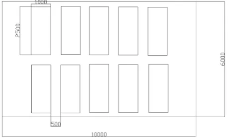
The experiment room shapes and sizes, 10 meters long, 6 meters wide, 3.6 meters high, 10 capillary radiation air radiant panels are installed on the roof of the experiment room. Each of the radiant panel area is 2.5 m2. The size and the location of the radiant panels are shown in Figure 1.
2.2. Measurement Parameters
The inlet and outlet water temperature of the capillary radiation air conditioning: temperature detectors are ar-ranged in the center of the water pipe.
The indoor temperature and humidity: detectors are arranged 0.1 m above the surface of the cooling panels. The outdoor temperature and humidity: detectors are arranged outdoors.
The cooling ceiling surface temperature: detectors are arranged in the intermediate position of the cooling ceiling.
The top space of the cooling ceiling temperature: detectors are arranged on the cooling ceiling’s top space. The water flow of the cooling panels: measured with a rotameter [3].
3. The Arrangement of Dew Point Temperature Detectors
Dew point temperature detector is a fairly expensive device, and its arrangement directly affects the accuracy of the indoor dew point temperature, in the case to meet design specification we should reduce the detectors num-ber as far as possible, arrange the detectors most reasonable. That is to say, detectors are arranged in an area, their detection zone should cover all the area, at the same time each detector’s repeat detection area as little as possible.
Dew point temperature detectors are arranged according to their protection area, each dew point temperature detector protection area and protection radius is influenced by the height of the room slope of the housetop de-tectors sensitivity three main factors.
3.1. Dew Point Temperature Detectors Are Arranged as the Form of Square
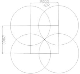
Each adjacent dew point temperature detector is arranged as square, the detectors are arranged in the center of the circles shown in Figure 2. Obviously, when the neighboring four detectors respectively to do circles with their detection radius R. If the detect radius is 1.5 m, then the separation distance of the detectors is 2.1 m, we can take an integer 2 m. Dew point temperature detectors are arranged according to the form of square is shown in Figure 3.
3.2. Dew Point Temperature Detectors Are Arranged as the Form of Triangle
[image:2.595.199.429.567.706.2]There is also a regular triangle arrangement, the detectors are arranged in the center of the circles shown in Fig-ure 4. Obviously, when the neighboring three detectors respectively to do circles with their detection radius R.
Figure 2. Detectors are square arranged.
[image:3.595.201.431.233.372.2]Figure3. The arrangement of detectors.
Figure 4. Detectors are square arranged.
If the detect radius is 1.5 m, then the separation distance of the detectors is 2.5 m. Dew point temperature detec-tors are arranged according to the form of triangle is shown in Figure 5.
3.3. The Comparison of Two Kinds of Dew Point Temperature Detector Arrangement To compare Figures 3 and 5, we can find that detectors are arranged as the form of triangle is more suitable. This way can not only satisfy the requirement specification, but also make the repeat detection range less than the square arrangement, it is more economic.
4. Results Analysis
4.1. To Compare the Dew Point Temperature of Cooling Panels Surface and Workspace (1.5 m)
Figure 5. The arrangement of detectors.
past people through research the temperature of the active area to prevent dew. But in fact the temperature change on the vertical space within a building, this is because of the different vertical air density and vertical air flow, so the dew point temperature is different between the ceiling radiant cooling panels surfer and the people active area .If arrange the dew point temperature detectors in the people active area, the result will lack of preci-sion. In order to better study the cooling panels dew problem, through compare the temperature and relative hu-midity near the surface of cooling panels and the active area. This paper defined distance 0.1 m is the surface of cooling panels. The calculate formula is shown as (1). The calculation results are shown in Figure 6.
( )
2t= −35.28896 2.03222 np 1.17025 np− Ι + Ι (1)
t Dew point temperature, ˚C; p Water vapor partial pressure, pa. [4].
Analysis Figure 6 shows that the dew point temperature of the active area is 0.8˚C higher than the ceiling ra-diant cooling panels surface.
4.2. To Determine the Inlet Water Temperature
Through the above analysis, detectors are arranged according to the form of triangle is more suitable for capil-lary plane radiation air-conditioning. So we arrange the detectors in the form of triangle, explore the relationship between the condensation critical condition on radiant cooling panels and inlet water temperature.
The air temperature and relative humidity of 0.1 m above the surface of ceiling radiant cooling panels to be measured, Check the enthalpy wet table to obtain dew point temperature, the dew point temperature and inlet water temperature of the capillary plane radiation air-conditioning to be compared. Conclusion can be obtained from Figure 7 that the design standard of the inlet water temperature to be set up 0.5˚C [5] higher than the dew point temperature of the surface of ceiling radiant cooling panels is safe.
4.3. The Relationship between Cooling Capacity and the Inlet Water Temperature
The inlet water temperature of capillary plane radiation air-conditioning cooling capacity is set to 15˚C, 16˚C, 17˚C, 18˚C, 19˚C and 20˚C, set indoor temperature to 27˚C.
(
)
C c A B
Q =h t −t A (2)
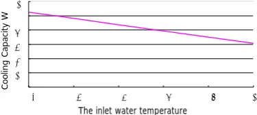
Qc cooling capacity, W; hc surface coefficient of heat transfer, W/(m2∙˚C), here take3.5; A radiant panel surface area, m2, A = 25 m2 [6]. The results are shown in Figure 8.
From the Figure 8 we can see with the increase of inlet water temperature, the capillary plane radiation air-conditioning cooling capacity will reduce. So it is important to choose a suitable inlet water temperature, if the inlet temperature is lower than the dew point temperature, it will produce a condensation phenomenon. If the inlet temperature is too high, the capillary plane radiation air-conditioning cooling capacity will reduce, affect-ing the coolaffect-ing effect of air conditionaffect-ing room.
5. Conclusion
Figure 6. The dew point temperature.
Figure 7. The relationship between the dew point temperature and inlet water temperature.
Figure 8. The inlet water temperature ˚C.
specification, but also make the repeat detection range less than the square arrangement, it is more economic. The inlet water temperature to be set up 0.5˚C higher than the dew point temperature is safe. At the same time the inlet water temperature can't be too high, because the capillary plane radiation air-conditioning cooling ca-pacity will reduce with the increase of inlet water temperature. When indoor design temperature is 26˚C to 28˚C, relative humidity is 40% - 60%, the dew point temperature is 14.5˚C to 19.5˚C, so the inlet water temperature can be set as 15˚C to 20˚C [7-9].
References
[1] Bu, W.F., Wang, S.H., Shang, C.G. and Cao, Z.Q. (2001) Experimental Study of Cooling Ceiling System. Building
Energy & Environment, 3, 7-11.
[2] Zhang, L., Liu, X.H. and Jiang, Y. (2011) Experiment and Performance Analysis on Convection Strengthened Radiant Panel. Journal of HV&AC, 41, 38-41.
[3] Ma. Y.-Q., Liu, X.-L., Li., Y.-A., et al. (2007) An Analysis of Condensation Process on Ceiling Radiant Cooling Pa-nels. Journal of Shandong Jianzhu University, 22, 537-540.
[4] Sun, J.J. (2008) Research on Dynamic Simulation and Control System of Capillary Plane Radiation Air-Conditioning . Shandong Jianzhu University Academic Dissertation.
[5] Xue, H.X. (2009) Research on Comfort and Airflow in Rooms with Capillary Air-Conditioning Systems. Shandong Jianzhu University Academic Dissertation.
[6] Huang, Y.Y. and Zhang, L. (2003) Dehumidification for Floor Cooling. Journal of HV&AC, 33, 47-51.
[7] Liu, S., Liu, X.H. and Jiang, Y. (2010) Dedicated Outdoor Air System in the THIC Air Conditioning System (1): Cal-culation of Space Moisture Load. Journal of HV&AC, 40, 80-84.
0 5 10 15 20 25
1 2 3 4 5 6 7 8 9 10 11 12
working condition
dew point temperature of the active area
dew point temperature of the ceiling radiant cooling
panels surface 0 5 10 15 20 25
1 2 3 4 5 6 7 8 9 10 11 12
The relationship between the dew point temperature and inlet water temperature
t
℃ dew point temperature of the ceiling radiant cooling
panels surface
Inlet water temperature
0 200 400 600 800 1000 1200
15 16 17 18 19 20
Co ol in g Cap ac ity W
[image:5.595.217.405.348.432.2][8] Olesen, B.W. (1997) Possibilities and Limitations of Radiant Floor Cooling. ASHRAE Transactions, 103, 42-48.