Control of electrodeposit properties of nickel and nickel
alloy by pulse plating.
HADIAN, Seyed E.
Available from Sheffield Hallam University Research Archive (SHURA) at:
http://shura.shu.ac.uk/19737/
This document is the author deposited version. You are advised to consult the
publisher's version if you wish to cite from it.
Published version
HADIAN, Seyed E. (1990). Control of electrodeposit properties of nickel and nickel
alloy by pulse plating. Masters, Sheffield Hallam University (United Kingdom)..
Copyright and re-use policy
100305413 7 TELEPEN
Sheffield City Polytechnic Library
ProQuest Number: 10697039
All rights reserved INFORMATION TO ALL USERS
The quality of this reproduction is dependent upon the quality of the copy submitted. In the unlikely event that the author did not send a com plete manuscript and there are missing pages, these will be noted. Also, if material had to be removed,
a note will indicate the deletion.
uest
ProQuest 10697039
Published by ProQuest LLC(2017). Copyright of the Dissertation is held by the Author. All rights reserved.
This work is protected against unauthorized copying under Title 17, United States C ode Microform Edition © ProQuest LLC.
ProQuest LLC.
789 East Eisenhower Parkway P.O. Box 1346
CONTROL OF ELECTRODEPOSIT PROPERTIES OF NICKEL AND NICKEL ALLOY BY PULSE PLATING
BY
SEYED ESMAIL HADIAN
A THESIS SUBMITTED TO THE COUNCIL
FOR THE NATIONAL ACADEMIC AWARDS
IN PARTIAL FULFILMENT OF THE
REQUIREMENTS FOR THE DEGREE OF
MASTER OF PHILOSOPHY
NOVEMBER 1990
SPONSORING ESTABLISHMENT: SCHOOL OF ENGINEERING
SHEFFIELD CITY POLYTECHNIC SHEFFIELD, ENGLAND
COLLABORATING ESTABLISHMENT: INCO ALLOY PRODUCTS Ltd, WIGGIN STREET,
<
Th
3
.
2
PREFACE
The work described in this thesis was carried out at Sheffield City Polytechnic between the 1st March 1986 and May of 1989, under the Dr R.P. Stratton Director of Stud
ies, and Dr E. Jackson acted as adviser to August 1988. According to the regulations, a course in Metallurgical Process Management must be successfully completed. The details of the course are given below;
MODULE 1
(a) PROCESS METALLURGY (b) MECHANICAL METALLURGY (C) ADVANCED THERMODYNAMICS
MODULE 2
(a) ACCOUNTANCY
(b) MICRO-ECONOMICS AND FINANCIAL CONTROL
(c) COMPUTATIONAL METHODS AND OPERATIONAL RESEARCH
MODULE 3
(a) CORROSION RESISTANT AND HIGH TEMPERATURE METALS AND ALLOYS (b) POWDER METALLURGY
(c) CONTINUOUS CASTING
MODULE 4
CASE STUDIES
DECLARATION
During the period of registration for the CNAA degree of
MPhil the candidate has not been registered for any other
CNAA award or for a university degree.
The results and theories presented in thesis are original
except were reference is made to previous work.
Signed
Date : /jo/ /t
ACKNOWLEDGMENTS
The author would like to thank the Sponsoring Establish ment, Sheffield City Polytechnic, and particular thanks are due to my academic supervisors Dr R.P.Stratton and advisers Dr E.Jackson and Dr Marshall.
I would also like to thank the following establishments for either material, advice, or the use of equipment in specialised areas of the experimental work:
OMI International Coporation - Woking - Surrey - England
Brunei University- Uxbridge - Middlesex - England
Thanks are also due to all the technical staff in the materials Dept with particular reference to Mr P Slingsby and Mr M Muldowni.
CONTROL OF ELECTRODEPOSIT PROPERTIES OF NICKEL AND NICKEL ALLOY BY PULSE PLATING
ABSTRACT
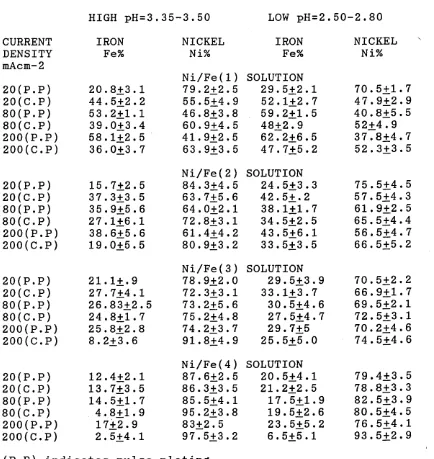
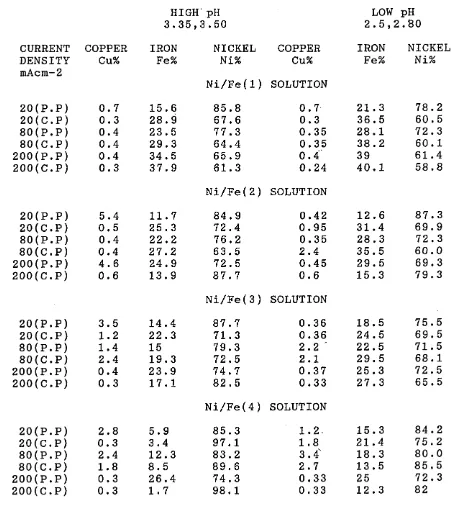
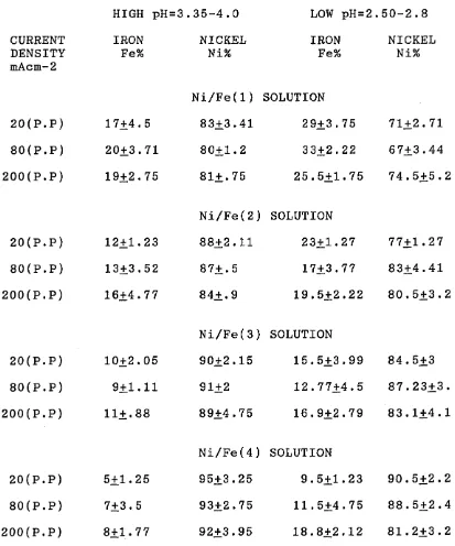
Pulsed-current electrolysis with various ratios of ’on*-time to ’off’-time have been applied to the deposition of Ni and Ni/Fe alloys from Watts and Ni/Fe baths.
The electro-depositions of nickel and nickel-iron alloy on copper and mild-steel substrates using Watts and Ni/Fe baths have been investigated. The mechanical properties of micro-hardness and internal stress obtained using the EFCO stress-meter and X-ray diffraction were measured as a function of bath composition, ’o n ’/ ’off’ cycles,current density, types of plating and solution pH.
The structure and composition of alloys deposited have been investigated using S.E.M and wet analyses. It has been shown that the composition of the Ni/Fe alloy depos its changed markedly with increasing current density and proved to be dependent on current density. Also, the composition and properties of electrodeposited Ni/Fe alloy have been related to the composition of electrolyte and the deposition conditions.
CONTENT
PAGE
1.O-INTRODUCTION 9
2.O-LITERATURE SURVEY 11
2.1-Basic electroplating theorv 11
2.2-The terminology of pulse plating 12 2.3-Origins and developments of electroplating 14
2.3.1-Historical origins 14
2.3.2-Applications of electroplating 15
2.3.3-Electroforming 16
2.3.4-Nickel-Tron allovs 18
2.3.5-Pulse plating of Ni alloys 21 2.4-Mechanism of general electrodeposition 23 2.4.1-Mechanism of alloy deposition 26
2.5-Electrode potentials 30
2.6-Electrolytic crystallization 33
2.7-Nickel plating solutions 36
2.7.1-Watts nickel plating solution 36 2.7.2-Bath composition and operating conditions 38
2.7.3 The nickel-iron plating 39
2.8-The origins of residual stress in electrodeposits 2.8.1-The crystallite-joining theories 41
2.8.2-Hydrogen theories 44
2.8.3-Changes in foreign substances theories 46
2.8 .4-Excess-energv theories 46
2.8 .5-Lattice-defects theories 48
2.9-The measurement of macrostress 50 2.9.1-Principles and problems of stress 51
2.9.2-Problems arising from use of stop-off
materials 54
2.9.3-Effect of temperature change 54
2.9.4-Calibration of stressmeters 56
3.0-EXPERIMENTAL METHOD
3.1-General description of the equipments 58
3.1.1-Power Mosfets 58
3.1.2-Oscilloscope 59
3.1.3-Power supply 59
3.1.4-Pulse generator 60
3.1.5-Copper coulometer 60
3.1.6-The EFCO-meter/Dilatometer, 61
3.1.6.1- Principle of operating of EFCO meter 61 4.0-EXPERIMENTAL DETAILS
4.1-Preparation of substrates 62
4.2-Preparation of Watts plating solution 62
4.3-Nickel-iron solutions 63
4.4-Preparation of copper substrate as
cathodes for plating 65
4.5-Progressive electrolytic purification of
plating solution via ’dummying* 66
4.5.1-Dummying 66
4.6-Use of conventional plating for varying current
densities of Ni/Fe solutions 67
4.7-Operation of periodic pulse plating 68 4.8-Plating and use of stressmeter using the strip
mild steel specimens 69
4.9-Micro-hardness determination 70
4.9.1-Scanning electron microscopy(S .E .M) 71
4.9.3-Adhesion determination 71 4.9.4- Current efficiency determination 72 4.9.5-Using x-ray diffraction to determine the
stress within deposits 72
5.0-EXPERIMENTAL RESULTS
5.1-Effect of current density on pulse and
conventional plating 74
5.1.1-Pulse plating 74
5.1.2-Conventional plating 77
5.2-Effect of concentration of electrolyte on
types of plating 78
5.3-Effect of pH on types of plating 80 5.4-Influence of duration of electrolysis on
types of plating 81
5.5-Effect of coating thickness with types of
plating and different substrates used 82
6.0-DISCUSSION
6.1-Effects of current densities upon deposits 83 6.2-Effects of plating conditions upon composition
of Ni/Fe alloys 85
6.3-Effect of coating thickness with types of
plating 91
6.4-Effect of on-time to off-time 92
7.0-CONCLUSIONS 95
8.0-SUGGESTIONS FOR FUTURE WORK 97
1.0-INTRODUCTION
Pulse plating has gained acceptance in some sectors of the metal finishing industry, especially electronics, gold plating and finally deecorative applications. The pulsed current has benefical effects on deposit properties, for
(1-2 )
example, many investigators' ' have reported that coat
ings with fine grain structure, high purity and low elec trical resistance can be obtained for copper, silver, gold and palladium.
Pulse plating can be defined as a method of elec troplating by means of an * on-off’ direct current or potential in place of the continuous direct current used in conventional plating. Electrodeposition of metals using pulsed-current electrolysis has been extensively studied in recent y e a r s ).Metals deposits produced by pulsed-current electrolysis have many properties distinguishing them from those obtained by direct current electrolysis. Nickel and nickel-iron alloy deposits have a number of applications as d e c o r a t i v e ^ ^ ,electroformed^®^ and finally
(7)
magnetic' ' materials.
A study of the effect of the plating variables on the electrodeposition of the nickel and nickel-iron alloy
(8
—
9)
deposits has been reported by others' '. Advantages of pulse plating were most frequently cited in this field. A higher average cathodic current density can be applied to the plating system for deposition due to the higher aver age concentration of metal ion in the diffusion layer.
to investigate the relationship between the processing conditions in a pulse plating bath and the properties of electrodeposited metal coatings. Also parameters control ling the formation of low stressed deposits and coherent alloy coatings of predetermined composition is to be established.
A plating unit is to be designed and constructed and electrodeposits formed using a D.C power supply having a variable ’o n 5 pulse time and variable ’off’ relaxation time.
The initial work will be concerned with evaluating the stresses within the deposits from Watts and Ni/Fe solu tions, and these stresses were measured using both mechani cal (dilatometric method) and X-ray techniques.
2.0 LITERATURE SURVEY
2.1 BASIC ELECTROPLATING THEORY^10~12)
Electrodeposition is the process of depositing a metallic coating or other conductive layer or surfaces by means of electrolysis or electrochemical processes ie passage of current from an anode of the metal which is to be deposit ed, to the cathode on the which the deposit is to be obtained by using Faraday's law.
The amount of metal theoretically deposited may be calcu lated as follows;
W = ItA/ZF... (1) where; W = weight of metal deposited
A = atomic weight of metal deposited Z = valency of deposited metal
F = Faraday's constant t = Plating time, Second I = Current
from (1 ) it follows that;
Atomic weight of component 1 gramme chemical equivalent
---Valency of above component Faraday's law states two principles;
(a) For the current (It), the weight of metal deposited is directly proportional to its chemical equivalent.
(b) The weight (W) of metal deposited is directly propor tional to the quantity of electricity passed ie current
(I )*Time(sec).
gramme.^ THE CHEMICAL EQUIVALENT can be defined as the weight of the component which will replace or combine eight parts of oxygen by weight.
THE VALENCY can be defined as the number of atoms of hydrogen which replace or combine with one atom of element or substance.
Therefore, for chromium deposition from the hexavalent state, 96,500ycoulombs (ampere seconds) deposit 8.67 grams of chromium.
1 coulomb therefore deposits 8.67/96,500 grams of chromi um.
One ampere hour is 1 ampere flowing for 3,600 seconds ie, 3,600 as coulomb.
Therefore 1 ampere hour deposits (8.67*3,600)/96,500=0.323 grams of chromium.
2.2 THE TERMINOLOGY OF PULSE PLATING
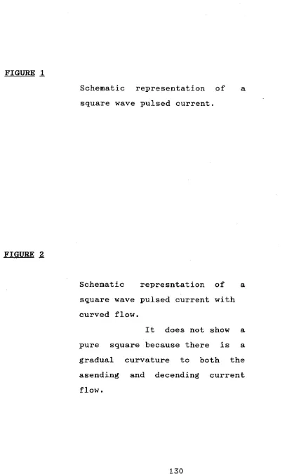
Pulse plating can be defined as current-interrupt ed electroplating. Figure 1 shows the typical square-wave form. Figure 2 is a typical oscilloscope trace of a square wave attainable with existing pulse equipment. However,
the figure does not show a pure square wave because there is a gradual curvature to both the asending and decending current flows. The curvature on the rising flow is inten tionally induced electronically to avoid an instantaneous rise and current overshoot.
periods of flow, there is greater opportunity for replen ishment of the cathode film through diffusion and convec tion. Cathode polarization is decreased, and cathode efficiency may be increased. Consequently, a higher cur rent density can be used and a desired thickness can be deposited in less time, even though the current is not flowing continously. In pulse electrolysis, selection of the electrolyte, peak current density, on-time, and off-time determine the physical characteristics of the elec trodeposits .
The process of pulse plating is that during the period when the current is on, the metal ions next to the cathode are depleted as in the normal way, but during the time that the current is off, the processes of mass transport via diffusion, ionic migration and convection, (both natural, and forced by agitation), have time to replenish the concentration of metal ions within the diffusion layer at the cathode, and do the same for negative ions in the analagous layer at the anode. When the current is then switched back on again,the cell can operate with better than average efficiency, reduced stress , and possibly higher than normal plating rates can be achieved even after the current * off*-time has been accounted for.
Desorption is defined as ions may break away from the metal surface and move off into the solution and new atoms may then ionise to replace the desorbed ions. Due to the desorption of decomposition products of salts, the metal density, the ductility, in certain cases even hardness increases and the tendency to produce porosity is reduced.
In pulse plating it is possible to control four parameters which will depend on the equipment used. Figures 1-2
(13-14)
illustrate these parameters and are followed as,
(1 ) width,(on-time), the length of individual pulses.
(2 ) delay,(off-time), the length of time between individu al pulses.
(3) frequency, the number of pulses of electricity and it can be expressed as;
F(frequency)=1/(on time + off time)
(4) current density, the amount of current per square centimeter supplied to the cell during each pulse.
2.3 ORIGINS AND DEVELOPMENTS OF ELECTROPLATING(15 ~ 2 3 ) 2.3.1 HISTORICAL ORIGINS
field coils to generate the heavy currents needed for electrolysis. The production of electricity by metallic corrosion in 1786 was followed by the reduction of metal ions to metal by electrons at a metal/solution interface.
(16)
Bugnatelli' ' published an account of silver ions as
early as 1805.
2.3.2 APPLICATIONS OF ELECTROPLATING
Electroplating is the process of depositing a coating having a desirable form by means of electrolysis. Its purpose is generally to alter the characteristics of a surface so as to provide improved appearance, ability to withstand corrosive agents, resistance.
The most potential industrial application of pulsed depo sition is in the process of alloy plating and electroform ing from simple ion solutions without the use of complex-ing agents.
Pulse plating is currently being used in gold plating with the great deal of success' '. This method gives a finer grained deposit and better electrical conductivity. This mode can produce fine-grained electrodeposits with better part to part distribution at as good or better than nomal plating rates.
composite nickel pulse chromium system. While nickel coatings may be applied solely for corrosion resistance where their inherent dullness is of no importance.
Gold electroplating processes have many important indus trial. An application particularly important, especially in recent years, is the application of gold plating proc esses to the manufacture of electronic circuits. Because of its electrical conductivity properties and the fact that it does not form a surface insulating layer, gold is especially useful as a conductor in electrical circuits as well as a surface metal in electrical contacting areas. Because of the extensive use of gold in electrical circuit as well as its high cost, it is advantageous to con serve as much as possible the amount of gold used in a particu lar application without sacrificing the quality of the electronic circuits.
Certain metallic substrates are traditionally difficult to plate with an adherent metal coating, for example;aluminum and aluminum alloys are characterized by numerous plating difficulties, including problems of adhesion of metal coatings. A solution to the problems inherent in plating aluminum is especially important due to present day needs for light weight vehicles.
2.3.3 ELECTROFORMING
/ oe o q \
mandrel' "* . The process of electroforming follows t h a t ^ ^ , metal ions by electro chemical are transferred through an electrolyte from anode to a surface of plated metal.
Most types of electroforming use nickel because it is
(27-31)
tough and strong and it is also highly resistance to erosion, abrasion and corrosive attack. The hardness of electrodeposited nickel varied between 150 and 600 Hv.
In order to lower the deposit stress, sulphur can be used but unfortunately it induces an embrittlement in
(33 )
deposits' . It is essential to ensure that internal stress in the deposit is zero, hence addition of organic stress reducing agent should be used in Watts solution
/ Q A A i Q/' \
whereas in sulphamate * ~ ' solution this stress can be reduced to zero at lower temperature (60°C). The hard ness can be varied between 150-450 Hv.
According to Watson and W o r n ^ ^ ^ , Ni speed is a most suitable process which has been developed by Inco to reduce the limitations of electroplating. This process does not involve the organic stress reducer and can be used at high current densities.
Electroforming has a wide range of application such as ( 3 7
27
) gramophone record production,printing applications' 1 , mould and dies, mesh products, foundry patterns, press tooi(34,36,38) Qr tools for texturing and leathergrain-(3 0 )
(3 2)
Wearmouth' ' has shown that cobalt or nickel deposits would be ideal for dies and moulds and with lower cobalt in solution and lower current density, a lower stress will result, but with increase in current density will reduce the deposit hardness.
2.3.4 NICKEL-IRON ALLOYS
Pulse plating of nickel-iron alloys has received considerable attention. Avila and Brown^^^ found that, with pulsing, the alloy composition was much closer to the solution composition, and was also independent of the
(41)
thickness of the deposit. Beltowska-lehman' ' investigat ed the effect of pulsing on the internal stress of thin permalloy films,(80Ni-20Fe) in order to control the mag netic properties. He found that pulsing, in fact, pro duced higher stress levels, particularly at higher fre quencies (500Hz) where the crystallite size was smaller. N i s h i z a w a ^ ^ found that pulsing resulted in permalloy films that were bright and had a fine grain size. The current efficiency, particularly for iron, was greatly improved and necessitated reducing the concentration of ferrous ions by one third compared with D.C plating.
ap-plied potential for current densities lower than the limiting current density. Simultaneously, experiments wih a pulsating potential enabled a reduced iron content in the alloy to be obtained either with increase in amplitude or reduction in frequency for the same average potential value. Other advantages include wider current density range for alloy plating. Faster coverage on molybdenum or tungsten surfaces and fifty microinches of pulse plated Gold seems to have the same corrosion resistance as 100 microinches of D.C plated Gold deposits.
The use of pulsed current is quite well known as a re search tool for studying the electrodeposition mechanism of metals.With increasing emphasis on the properties of the deposits, it is therefore realised that this method of deposition could well provide a means of improving their
(44)
properties. However, the good metal deposits are' ' produced by pulse plating in the frequency range of 10-500 Hz.
Ibl et a l ^ ^ have shown that, with using short pulses of large current amplitude followed by a relaxation time adequately long to allow complete relaxation of the diffu sion layer, good quality deposits can be obtained. Also Gurovich and Krivtzov^®^ have shown that increasing pause - to pulse ratio will result in a decrease in the surface roughness of metal deposits.
polarisation occurs during plating.
The other techniques include the effect of superimosing an a.c on d.c on the electrodeposition of Co-Ni alloys from a W a t t s ^ ^ . Also with higher frequencies, the capacitance current of the periodic charging and discharging of the double layer produces a smearing effect of the Farada-ic current wave as if the frequency though the overall current appears to be pulsating. However, lowered stress due to off period allows the mass transport to fill up depleted ionic concentration within the cathode diffusion layer, enabling the cell to utilise its current at in creased efficiency when the power is switched on again.
Llcarnini and I b / ^ ^ has reported that with pH=9 and high current density, it is possible to produce palladium coatings of 5 um thickness without cracks and porosity. As the current density (c.d) increases, the hardness and number of cracks decreases.
Hayashi, Kitanishi and F w k u m o t o ^ ^ have shown the effect of ‘off-time* [T] increases, with the duty cycle in the following order of 1/25 to 1/250, formation was favoured of granular growth to the block type deposits with the
o
result.
(51)
Popov, Maksinovic and Stevanovic' 1 have reported that with increasing pause - to pulse ratio in pulsating cur rent deposition leads to a decrease in the size and in crease in the number of growing grains.
(26)
Raub and Knodler' ' have reported that with polymer formation in deposits of hard gold , the nickel and cobalt content are increased and at the same time reduces the oxygen, carbon and nitrogen/hydrogen contents. High bright deposits can result from high nickel but low polymer concentration.
2.3.5 PULSE PLATING OF Ni ALLOYS
The most recent papers which presented by Cherkaoui et (52 )
a l v ' has demonstrated that pulse plating of Ni-Cu al loys, using 50-100Hz and pulse current density of 20-25 A
_ o
dm , has produced smooth and bright deposits with 30Wt.% Cu. The roughness was considerably reduced and brightness much enchanced as compared with d.c. plated alloys of the same composition.
Pulse plating of electrolytic copper was also investigated (53 )
by Montgomery' '. He carefully described that with posi tive and negative pulsing conditions the resistance and other relevant mechanisms could be influenced to improve the performance relative to DC.
Pulsed current electroplating of silver-gallium alloy was (5 5)
investigated by Reksc et a l v '. They showed that the codeposition of 4.0 to 4.5% gallium has increased the hardness of silver and improve wear resistance fourfold with only an insignificant increase in electrical resis tivity.
Current distribution in selective pulse plating was shown
( C c \
by Chin et al' . A mathematical model was represented for the distribution of the time averaged local current density on a large unmasked cathode, the cathode surface was facing a small rectangular anode in plating cell. Numerical computations were made for the pulse plating of gold from a concentrated neutral phosphate gold bath and copper from an acid copper sulphate bath.
2
Current pulses at 200 to 400 mA/cm with an on-time of 0.1 2
msec and an average current density of 4.0 mA/cm were the (5 7)
optimum pulsing conditions for Shan-Jiang' ' to deposit bright, smooth silver alloy containing about 25% palladi um. Deposit composition appeared to be controlled by diffusion polarization.
A study of the current efficiency decrease accompanying short pulse time for pulse plating was carried out by C h e n ^ ^ . He demonstrated that when the on-time was short er than a critical pulse time, the efficiency dropped noticeably.
ics of Ni-Fe-Co deposition . The reduction of Saccharine on the cathode causes easier hydrogen evolution. Hydrogen reduction rate increases as the intensity of agitation increases, this corresponds to the Saccharine reduction reaction being diffusion controlled.
2.4 MECHANISM OF GENERAL ELECTRODEPOSITION
Much effort has been given in recent years to studying the mechanism of electrodeposition. Most
investi-(59
)
gators' ' have assumed that electrodeposition should follow a mechanism akin to that for the deposition of a crystalline coating by condensation of a vapour. The solvated metal ion approaches and adsorbs on the cathode, losing some of its solvation sheath as the cathode gains the requisite electrons. The ad-ion which is mobile, diffuses over the cathode surface until it reaches an atomic step. It adsorbs on the step, losing more water of solvation, and reducing its freedom to diffuse along the step. Further desolvation and co-ordination follows when it reaches a kink in the step, at which stage it is mobi lised. When other ad-ions following this path eventully join and submerge the first, co-ordination occurs with metal ions in the metallic lattice. The view of Capuano
(KQ)
.
etalv ' was that the mechanism of electrodeposition was
plausible, compatible and consistent with later views on metallic crystals and their defects, and certain proper ties of electrodeposits.
charges, and migration of these ions in the solution constitutes a flow of electricity. Salts are electrolytes; they conduct electricity, not only in solution, but also in molten state. Such electrolytes are decomposed in the process called electrolysis, in which electrical energy becomes chemical energy. But chemical energy can also be converted to electrical energy.
A simple cell shown in fig 3 may be used to illustrate the mechanism involved. The potential difference across the cell due to the current source makes an excess of electrons available at the cathode as it becomes more negative than the anode. This potential attracts positive ions in the solution to the cathode where they are neutra lised either by free electrons in the lattice, or by ions accepting electrons and hence becoming incorporated into the lattice at the cathode surface. Whichever process by which the positive ions become neutralised at the cathode,
trans-port of metal ions through the solution. This hydrated ion in the solution is then attracted to the cathode and becomes incorporated in the cathode lattice as it sepa rates from the water molecule which stays in the plating solution and can then contribute to further metal ion transport. The anodic and cathodic processes are neces sarily self-regulating and occur on average at the same rate, simply because the cell potential governed by the external power supply is common to both electrodes.
Any difference in reaction rates at either electrode leads to a change in the potential which slows down the reaction rate at whichever electrode is involved, . speeding up the reaction rate at the other in order to equalise the rates.
/ £ n _ £ 1 \
dipoles become components of the double layer.
/09 — 64 )
Brandes, Erdey-Gruz and Volmer' ’ have mentioned that the dehydrated metal ion migrates within the outer zone of the double layer to a point opposite an energetically favourable growth point on the cathode surface. From this point the metal ion passes through the double layer, is neutralized, and deposited on the cathode. According to
/ C c \
Kohlschutter' ', the metal ion passes through the double layer at the point where contact first occurs. It is then neutralized and adsorbed for the time being at the cathode surface as an ad-atom. This ad-atom now diffuses on the cathode to a growth point and is there incorporated into the crystal lattice of the cathode. Only when the first contact chances to be at the site of a growth point of a crystallite can it immediately be built into the crystal lattice.
2.4.1 MECHANISM OF ALLOY DEPOSITION
The principal factors that determine if two metals can be codeposited from an aqueous solution and the ratio of the metals in the resultant deposit produced at any given temperature and current density are as follows;
1. The static or equilibrium potential of each metal in that type of bath
2. The cathode polarization of each metal in the presence of the other, the cathode polarization existing during codeposition
4. The solution potential, the dissolving tendency of the alloy deposit that is or may be formed
5. The hydrogen overvoltage on the resultant cathode alloy surface.
In addition, the results will be influenced by the effects of temperature and current density upon each of above properties. Even though the direction of the effect of each single variable can often be predicted, it is not yet possible to estimate the. magnitude of such changes, espe cially if two or more conditions are simultaneously varied.
Fig 5 shows three typical cases for two simultaneously deposited cations A and B. In fig 5A , the two cathode potential-partial current density curves are far apart. During electrolysis the cathode assumes the discharge potential of the more noble metal. The cathode process consists of the discharge potential of the more noble metal. The cathode process discharges the cations of metal A and the deposition potential of the metal B is not attained. At the potential E-^, the limit current density ij^m of the more noble cation is attained. The potential E-£ then becomes suddenly less noble until discharge of the cation B begins as the second reaction. With further increase in current density, cation B is increasingly discharged, while deposition of the metal A remains the same on an absolute scale but decreases on a percentage scale.
which are close to each other. The deposition potential of the less noble metal is attained even at relatively low current densities. Thus, codeposition of B is possible before the limit current density of A is achieved. At the potential E-p the corresponding partial current densities are i^ and ig ^ and at the potential E £ » i^,2 anc*
The conditions for the simultaneous deposition of two
metals are most favourable when the cathode potential-current density curves are identical. This case, however, can hardly be realized in practice.
Fig 5C. illustrates two intersecting cathode potential partial current density curves. At the potential E-^ the partial current densities are 1^,1 anc* ^B,l ^ A , l > ^B,l^* At the potential E2 the partial current densities are equal and thus the current efficiency for both A and B is 50%. At the potential Eg the partial current density is ifi 3 > 3 . With such a curve trend, the partial current density ig increases more rapidly with increasing current density than does i^. This means that the current effi ciency decreases with respect to the cation A . In prac tice , various values for the current efficiency may be found depending on the relative positions of the cathode potential partial current density curves.
/eg \
solutions of unit activity are +0.34V and -0.76V respec tively and the corresponding potential-current density curves are shown in fig 6 .
Fig 6A. shows clearly that there is no potential which could be applied at which both metals could be simultane ously deposited from these acid solutions. All the copper would be deposited first and then the zinc. The effect on the E-i curves using the cyanide solution is shown in fig 6B. Thus, simultaneous co-depostion is now possible. The reason for this behaviour is that the formation of com-— 18 plexes reduces the activity of copper ions to about 10 g ions/1 although the concentration of copper in solution is about 1 mol/1. The copper ion is Cu+ in the complex and E for this ion is +0.55V. The zinc complex ion is relatively
O 4.
weak but the activity of Zn ions in solution is not as markedly affected.
( fi 7 — 7 fi )
The simplest nickel-iron plating baths' ' are based on the sulphates, chlorides or sulphates and chlo rides of the two metals. Stabilizers or complexing agents
are often used to diminish the formation of insoluble
+ 3
ferric hydroxide, ie Fe and organic hydroxy carboxylic acids are satisfactory.
E = E°+(RT/ZF)logea
where;
R= gas constant = 8.31
T= absolute temperature =298 K Z= valency of the reacting ions F= Faraday constant =96500 Coulomb
The discharge potential for deposition also depends upon the over-potential*? and is given by;
Hence for two metals to simultaneously deposit, their potentials must be equal, so;
For the iron-group metals the standard electrode potential are -0.250 V for nickel, -0.440 V for iron.
2.5 ELECTRODE POTENTIALS
An aqueous electrolyte solution con sists of a variety of charged and uncharged species as follows;
(1 ) cations, which are positively charged ion and migrate to the cathode in a galvanic or voltaic cell,
(2 )anions, which are negatively charged ion; they migrate to the anode a galvanic or voltaic cell,
= E°+(RT/ZF)logea - ^
/
/
(3)water dipoles,
An electrical double layer(E.D.L) and also known as the (Helmholtz double layer) is the combination of the posi tive "adsorbed fixed layer" outside and the negative ions diffuse from it to form a "diffuse mobile layer" shown in fig 8 . These layers are loosely held there by electro static attraction. The potential between the layers is a result of the equilibrium of the chemical and electrical forces. The potential difference which exists between metal and solution in the equilibrium state is known as the galvanic potential. This electrochemical equilibrium is dynamic, so that in the equilbrium state the interac tion between metal and electrolyte does not cease although
in a given interval of time the number of ions entering the solution from the metal is equal to the number of ions deposited on the metal from the solution. Nernst termed the tendency of the metal to send ions into solution the electrolytic solution pressure and the tendency of the solution to be diluted by depositing ions on the metal, the "osmotic pressure" of the ions.
from solution into the metal lattice, the metal is at the positive side of the E .D .L ,opposed to which is the nega tive side in the adjacent solution layer. When ions escape from the metal and enter the solution ,the metal ion is at the negative side of the double layer and the adjacent solution layer at the positive side. The magnitude of the galvanic potential depends upon which of those processes predominates.
A simple mode of the ( E.D.L) was suggested by Helmholtz in which the changes at the interface were regarded as the two plates constituting a parallel plate capacitor , eg, a plate of metal with excess electrons (the inner Helmholtz plane- I.H.P) and a plate of excess positively charged ions (the outer Helmholz plane-0.H.P) in the solution adjacent to the metal. The changes at the interface bal
ance one another so that the E.D.L is neutral as a whole. Fig.8A shows the E.D.L to consist of a plate of excess negative charges on the surface of the metal.
2.6 ELECTROLYTIC CRYSTALLIZATION
The final step which takes place during the electrodeposition of a metal at the cathode is known as electro-crystallization ie, the transition of the dis charged metal atoms into the crystalline state.
corners, where the highest current densities are present and secondly, at the centres of the crystal planes. The type of growth which predominates depends on the minimum crystallization energy.
(77)
According to Kosselv , the energy required for continua tion of the growth of a given crystal lattice is least where the newly arrived atom can be built into an unfin ished lattice plane. Owing to the minimal energy require ment for crystallization at these points, this partial step is repeated many times. Crystal growth thus proceeds by "repeatable" steps called "half-crystal" positions and also called "active" and "growth areas" by Fisher and
(7Q —70 )
Lorenz ' '. The forces of attraction in the interior of a metal are compensated by the neighbouring atoms. However, At the surfaces, this is no longer true, and they thus exert growth in the vicinity of the surface. Therefore, these growths are strongest at corners and
(62)
edges projecting from the surface' ' . At the growth areas crystallization proceeds in such a manner that one ad-atom at a time is built into the crystal lattice in the immediate vicinity of an atom previously incorporated into the lattice.
2.7 NICKEL PLATING SOLUTIONS
Commercial nickel plating started about 60 years ago,and for around 30 of those years the*WATTS NICKEL’ solution has dominated the field. This solution is based upon Nickel sulphate to provide the necessary ions, with chlo ride to aid anode dissolution and boric acid to act as a buffer. In 1938, the first large scale competitor to the WATTS solution emerged. This was the first of the sulpha-mate solutions and was developed by Cambi and P i o n t e l l i ^ .It was some years until the sulphamate (
81)
solution became commercially viable,but in 1950,Barret' introduced the process into the American electroplating industry.During the 1950’s much work was carried to research and develop commercial sulphamate solutions such as by D i g g i n ^ ^ in the U.S.A, C h a e t a l ^ ^ in India and Fanner and Hammond in the U.K.
The development by K ^ n d r i c k ^ ^ of the concentrated nickel sulphamate bath in 1964 led to the patenting of the *NI-SPEED PROCESS’ by international Nickel limited.The impor tance of this development over the well-established WATTS solution is that the concentrated sulphamate bath allows very high plating rates to be achieved whilst still re taining good mechanical properties and the control of internal stresses.
2.7.1 WATTS NICKEL PLATING SOLUTION*11)
The basic constituents of this bath are;(c) Boric acid.
Other additions such as; Wetting agents, Anti-pitting agents and brighteners mav be added.
(a) Nickel sulphate provides the majority of the nickel ions necessary and is used because it is relatively cheap compared with other Nickel salts, is readily water soluble and produces a stable anion which is not volatilized,reduced at the cathode or oxidised at the anode. By increasing the nickel sulphate concentration of the Watts solution and increasing the current density (C.D) of the bath, the plating rate can be increased and plate distribution improved.
(b) Nickel chloride functions to provide of the chloride ions chiefly to improve anode dissolution by reducing polarization which prevents passivation. Its presence also decreases the bath resistivity and improves its efficiency and throwing power.
(c)Boric acid acts as a buffer to control the pH of the solution in the cathode film, and its absence may lead to hard, Cf*<^_ked and pitted deposits as shown by
( o g \
2,7,2 BATH COMPOSITION AND OPERATING CONDITIONS
The main operating variables for the Nickel plating solu tion are (a) pH range, (b )temperature range and (c) compo sition and cathode current density.
(a) pH RANGE
The normal operating range of pH is between 1.5 and 4.5. The higher pH tends to increase stress and the deleterious effects such a s ;impurities on deposit properties can become marked above pH=5. Low pH may allow the cathode current density range to be increased, but it has been
(8
7
)
found' ' that the optimum range for best deposit proper ties and operting efficiency is around 3.0-4.0.
(b) TEMPERATURE RANGE
The accepted operating range is between 45^C and 65^C within this range, the effects of ion mass transport by diffusion are increased. Temperatures below this range reduce the above effects and temperatures above this range may be impractical as they could be expensive to maintain on a large commercial scale.
(c) COMPOSITION:
A typical composition^^ ^ would be;-Nickel sulphate : 330 g/1 Nickel chloride : 45 g/1
Boric acid : 38 g/1
nickel chloride concentrations above 50 g/1 also are unimportant.
(d) CATHODE CURRENT DENSITY
A typical r a n g e ^ ^ for the composition given is
_ 9
25-100mAcm . Low current densities may produce bright brittle deposits, intermediate current densities ,(say 50
_ o
mAcm ), give a smooth, ductile well adhered deposit. Whereas at the highest current densities, powdery depos its, ’burnt* appearance on leading edges, and eventually high residual stress leading to gross peeling will occur.
2.7.3 THE NICKEL - IRON PLATING^86“97)
The attraction of nickel-iron plating process is related to evidential metal cost savings which can be achieved. C l a u s s ^ m e n t i o n e d that this cost saving is due to the cost of iron being about 8% of the nickel.
The plating utilities and advantages of Ni/Fe plating include;
(i) The Ni/Fe replates much superior than frequent/normal Ni and covering power is excellent.
(ii) Inferior and reject parts can be run through again without uncovering/stripping.
(iii) The most main economic advantage over Ni plating is that iron is so much cheaper than nickel metal and this will be particulary important if the cost of nickel continues to rise.
(iv) Saving of Ni metal costs according to the
compa-(91 )
(v) The amount of of Ni waste is noticable and can be recycled.
2.8 THE ORIGINS OF RESIDUAL STRESS IN ELECTRODEPOSITS *98 ^ Owing to the complex nature of electrodeposition and the large number of interrelated variables involved with the plating process, there is no single overall theory cover ing the causes of residual macrostress. There are,
howev-/ Qg \
er, a number of theories, reviewed very well by Weil' '
and the one point upon which they are in general agreement is that macrostress is due to one layer of electrodeposit ed atoms fitting the one beneath it and subsequently shrinking or expanding, or the layer of atoms is deposited in such a way that it has to be either in compression or tension in order to fit.
The theories proposed to explain these conditions a r e :-1. The crystallite - joining theories.
2. The hydrogen theories.
3. Changes in foreign substances theories. 4. Excess energy theories.
5. Lattice-defect theories.
2.8.1 THE CRYSTALLITE - JOINING THEORIES
The basis for this theory overall is that crystal line material growing outward from several nuclei on the deposit surface is pulled together upon meeting, this causing stress. This was first postulated in 1918 by
/ /> r \
Fedot’ 100) pu^ forward similar theories in 1959 and 1966, adding that the resulting volume decrease upon recrystallization, (to a more dense state ), would produce a tensile stress. Thus, stress-reducing additions could fill the intercrystalline spaces prior to recrystalliza tion more effectively than other foriegn substances, thereby impeding or preventing the volume change and the resultant residual stress. Some doubt, however, has been cast upon the recrystallization of an aggregate of small grains causing macrostress, since firstly this theory cannot explain how compressive stresses develop, and secondly, high macrostress deposits are generally columnar grained - there being no evidence that they formed ini tially as fine grains.
tion since the latter and former are difficult to distin guish. For instance, tensile stress may be decreased by filling the gaps between joining crystallites thus imped ing their coalescence - the same idea as with recrystalli zation. Other effects include the changing of preferred orientation of crystallites due to the foreign substances leading to a greater degree of misfit upon coalescence which will give higher residual macrostress. Also, the attractive forces between crystallites may be altered by impurities which may lead to variations in internal stress.
Many observations have been made where, as the current density rises, so the residual macrostress rises^®®*^®^ 106). This could be due to increased nucleation rate caused by an increase in the overpotential, leading to more joining crystallites. The effect of impurities could provide exceptions to this behaviour due to their reaction to the overpotential.
The electrodeposition process is generally one of the continuous growth or ’flow* of single or multi-atom layers over the crystal layer beneath. In the absence of impuri ties and with single crystal deposits, the edges of such growing layers should be smooth leading to the joining of crystallites without misfit and therefore without stress. This has been proved experimentally by Schneider and W e i l ^ ^ ^ using a purified electrolyte. In the presence of impurities acting as growth inhibitors, however, the growth layers do not have smooth edges, leading to the joining crystallites touching at irregularities protruding from the growth layer first, leading to premature coales cence, (as if two liquid drops were meeting), and the pulling in of the crystallites forming stress. The effect of stress reducing additions could be to fill in the gaps or steps around irregularities thus promoting a smoother growth edge around crystallites, thus delaying coalescence so that when the crystallites do join they do not have so far to move upon coalescence, leading to lower stress.
2.8.2 HYDROGEN THEORIES
This assumes that a layer of deposit contains hydrogen which may combine with the metal deposit to form a hydride. The hydride then is assumed to decompose lead ing to a decrease in volume, and the outward diffusion of hydrogen. The substrate and deposit layers beneath this shrinking layer resist the contraction, and a tensile stress is caused.
forms gas pockets. This is a similar effect to hydrogen embrittlement, and the high pressure inside these pockets could lead to an expansion of the deposit and a resultant compressive stress in that layer.
Some evidence for the validity of this theory is that a strip bent in a way indicative of a tensile stress in a deposit can be straightened by hydrogen charging according to Hothersall(108 ),
The stress minimum observed at some intermediate current density of certain nickel deposits can be explained in terms of the hydrogen theory. The limiting current density for hydrogen deposition could be reached below the in termediate value of current density where the stress minimum has been observed. Thus, at lower current densi ties there would be more hydrogen to enter and cause stress in the deposit.
The interaction between hydrogen and foreign substances is not clear, but it is thought that certain impurities may combine with hydrogen and prevent any volume decrease in the deposit, leading to a decrease in stress.Conversely, impurities could provide sites for hydrogen to form gas pockets and give an increased residual stress.
stress in deposits, as stresses have been observed when there was no hydrogen codeposition^"^ ^.
2.8.3 CHANGES IN FOREIGN SUBSTANCES THEORIES
Alterations in the shape, orientation or chemical composition have been postulated to cause the volume change of a plated layer relative to the one above or beneath it, leading to stress.
The codeposition of foreign substances does not, according to Popereka^ etal, cause a macrostress as long as their distribution and concentration do not change with thickness, and the substances themselves do not undergo any changes. The theories involving volume changes due to the decomposition, dehydration or orientation changes of foreign substances do not appear to have adequate experi mental support, and must be held in some doubt. The effect of foreign materials on stress can be explained in a more experimentally consistent way by the effect that materials have upon lattice defects such as dislocations and vacan cies .
2.8.4 EXCESS-ENERGY THEORIES
Later in 1947, Soderberg and Graham^^^^, postulated that a high overpotential was equivalent to a high temperature at the deposition surface, said to be due to the heat of neutralization of ions upon being incorporated in the lattice at the cathode.
The contraction upon * cooling’ was said to provide the volume change necessary to explain the macrostresses produced.
A later amendment to these theories was made by Gabe and W e s t f ^ ^ who said that a high effective surface tempera ture was reached only as far as the number of vacancies which are produced in the deposit. Other workers compared the excess energy due to the overpotential with the stored energy in the stressed deposit and found them to be of similar orders of magnitude. It must be noted, however, that microstresses must also be accounted for in the calculation of stored energy.
Finally, whilst overpotential and macrostress are related in some way, and can be a way of storing energy in the deposit, other factors such as microstress and defects which are also areas of high energy, can not be ignored. The excess-energy theory, therefore is simply another complicating factor in the theory of stress and must be taken into account along with all the other factors.
2.8.5 LATTICE-DEFECTS THEORIES
theory of metals. The best developed of these is t h o u g h t ^ ^ ^ to be that which explains residual macros tress in terms of the lattice mismatch between deposit and substrate of different metals under conditions of assumed epitaxy, (i.e, the deposit continues the structure of the substrate). The greater this mismatch or misfit between the lattice parameters of the deposit and substrate, then the greater the associated strain energy. This high strain
energy can be relaxed by the creation of edge disloca
tions, (either positive or negative), so long as a reduc tion in total energy is achieved overall. Thus, at a certain misfit value, it becomes energetically favourable for so-called ’misfit dislocations’ to form.
Two dimensional arrays of such dislocations have been /iif? — 1 1 7 )
observed by Thompson and Lawless' ' in both nickel and gold deposited on copper. There is little doubt, now, as to the existence of these misfit dislocations.
Apart from the lattice mismatch itself, the rate of growth of deposits has an effect upon the development of misfit dislocations. If the growth rate is so fast, (e.g, at high current densities), then the lattice strain energy due to mismatch can not be relaxed quickly enough by dislocation formation and this could lead to the formation of three-dimensional deposit nuclei as a means of energy reduction - this in turn giving a high residual stress.
when the deposit does not take up same structure as the substrate, and other theories have then to be invoked.
However, dislocations in electrodeposited metals are not of the simple edge type, but are complex and often tan gled, therefore the mechanism by which dislocations cause internal stress are not quite clear.
2.9 THE MEASUREMENT OF MACROSTRESS
INTRODUCTION
The first records of stress measurement was car ried out by G o r e ^ ^ ^ in 1855 and some twenty years later, M i l l ^ * ^ and Booty came the first attempt to measure the stresses in electrodeposits. These electrodepositors understood not only the essential nature of the phenomenon but also its damaging action either because the deposit parted from substrate and (and then itself deformed) or because - where the substrate was thin section - the stress resulted in deformation of the whole assembly. Subsequently, other and equally harmful effects related to stress were revealed, including;
(a) The reduction of the fatigue life of components plated with a deposit in tensile stress, even though its adhesion was apparently unaffected.
(b)Enhanced corrosion and corrosion cracking have also been traced back to stressed deposits, not to mention more obvious phenomena such as blistering. From this point, these followed naturally a desire to measure such stress and a number of methods have been devised for this pur pose, which will be considered here.
2.9.1 PRINCIPLES AND PROBLEMS OF STRESS MEASUREMENT
The basic principle of electrodeposit stress measurement is either to measure the deformation of a substrate onto which a metal has been plated or opposed such deformation with a counter-face, which is itself measured.
The weakness in the first of these two approaches is that the deformation which allows stress to be measured, itself relieves that stress and to that extent corrupts the resulting measurement. There is a further subdivision possible in respect of the former category. In some meth ods, the deformation takes place during the electrodeposi tion. In others, the substrate is rigidly held and no deformation is possible until completion of the experi ment. The constraint is then released where upon the deformation.' occurs and can be measured.
The more sophisticated stressmeter incorporates a stiffer substrate, whose deformation will therefore be smaller. To compensate for this, some form of "amplification" is therefore included so that the actual measurement may be sufficiently sensitive. Among the methods used to achieve such "amplification" one may list the following;
(a) Gearing (Brenner-Senderoff) (b) Optical lever (HooT Arrowsmith) (c) Electrical amplification(Roch) (d) Hydraulic (Kushner)
(e) Vernier scale (Boeing)
errors.
It was recognised quite early on that the longer the substrate, the greater the deflection, the actual dis placement being cumulative. Thus many stressmeter designs are based on spirally-wound substrates (Brenner - Sender-off, Boeing) or long strips (Hoar -Arrowsmith, the IS meter (Dilatometer).
In comparison of stresses, rather than measurement of absolute values, it is important that similar thickness of deposit are used for comparison. The relationship between deposit thickness and stress is considered below. The immediate implication of this is that, in order to use a stressmeter correctly, a constant current power supply (not constant voltage) should be used, and deposits should be formed at set current values and for known times.
face of their spiral.
2.9.2 PROBLEMS ARISING FROM USE OF STOP - OFF MATERIALS Many designs of stressmeter require that one surface of the cathode be insulated by the use of some stopping - off material or resist, but difficulties arose from the dangers inherent in this, which include;
(a) Contamination of the test solution with species leached out from the resist - which may alter the stress level in electrodeposits.
(b) A swelling of the stop-off layer due to uptake of water leading to a change in stress, (it can be assumed that application of a stop-off layer will itself apply a stress but this, if curing complete, will be taken up in the instrument zeroing procedure.
(c) A contamination, by the stop - off material, of the working surface, as a result of "creep" action.
The use of "permanent"stop - off has largely removed such problems.
2.9.3 EFFECT OF TEMPERATURE CHANGE