IEEE TRANSACTIONS ON NUCLEAR SCIENCE, VOL. 51, NO. 3, JUNE 2004 909
The Second Level Trigger of the ATLAS Experiment
at CERN’s LHC
A. dos Anjos, M. Abolins, S. Armstrong, J. T. Baines, M. Barisonzi, H. P. Beck, C. P. Bee, M. Beretta, M. Biglietti,
R. Blair, A. Bogaerts, V. Boisvert, M. Bosman, H. Boterenbrood, D. Botterill, S. Brandt, B. Caron, P. Casado,
G. Cataldi, D. Cavalli, M. Cervetto, M. Ciobotaru, G. Comune, A. Corso-Radu, E. Palencia Cortezon, R. Cranfield,
G. Crone, J. Dawson, B. Di Girolamo, A. Di Mattia, M. Diaz Gomez, R. Dobinson, J. Drohan, N. Ellis, M. Elsing,
B. Epp, Y. Ermoline, F. Etienne, S. Falciano, A. Farilla, M. L. Ferrer, D. Francis, S. Gadomski, S. Gameiro,
S. George, V. Ghete, P. Golonka, S. González, B. Gorini, B. Green, M. Grothe, M. Gruwe, S. Haas, C. Haeberli,
Y. Hasegawa, R. Hauser, C. Hinkelbein, R. Hughes-Jones, P. Jansweijer, M. Joos, A. Kaczmarska, K. Karr,
A. Khomich, G. Kieft, E. Knezo, N. Konstantinidis, K. Korcyl, W. Krasny, A. Kugel, A. Lankford, G. Lehmann,
M. LeVine, W. Li, W. Liu, A. Lowe, L. Luminari, T. Maeno, M. Losada Maia, L. Mapelli, B. Martin, R. McLaren,
C. Meessen, C. Meirosu, A. G. Mello, G. Merino, A. Misiejuk, R. Mommsen, P. Morettini, G. Mornacchi, E. Moyse,
M. Müller, Y. Nagasaka, A. Nairz, K. Nakayoshi, A. Negri, N. Nikitin, A. Nisati, C. Padilla, I. Papadopoulos,
F. Parodi, V. Perez-Reale, J. Petersen, J. L. Pinfold, P. Pinto, G. Polesello, B. Pope, D. Prigent, Z. Qian, S. Resconi,
S. Rosati, D. A. Scannicchio, C. Schiavi, J. Schlereth, T. Schoerner-Sadenius, E. Segura, J. M. Seixas, T. Shears,
M. Shimojima, S. Sivoklokov, M. Smizanska, R. Soluk, R. Spiwoks, S. Stancu, C. Stanescu, J. Strong, S. Tapprogge,
L. Tremblet, F. Touchard, V. Vercesi, V. Vermeulen, A. Watson, T. Wengler, P. Werner, S. Wheeler, F. J. Wickens,
W. Wiedenmann, M. Wielers, Y. Yasu, M. Yu, H. Zobernig, and M. Zurek
Abstract—The ATLAS trigger reduces the rate of interesting events to be recorded for off-line analysis in three successive levels from 40 MHz to 100 kHz, 2 kHzand 200 Hz. The high level triggers and data acquisition system are designed to profit from commodity computing and networking components to achieve the required performance. In this paper, we discuss data flow aspects of the design of the second level trigger (LVL2) and present results of performance measurements.
Index Terms—ATLAS, cluster, data acquisition, high-energy
physics, network, object oriented, performance, testbed, trigger.
I. INTRODUCTION
T
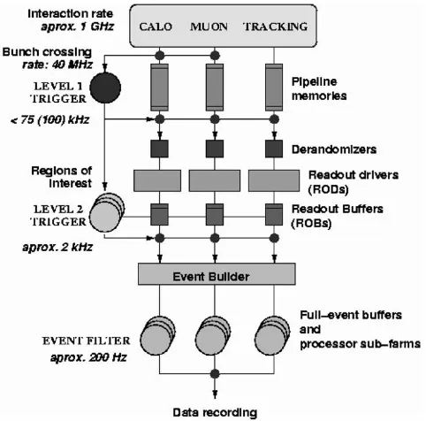
HE ATLAS experiment [1] will use very high energy proton-proton collisions provided by CERN’s LHC for a wide research program including a search for Higgs bosons. The detector is composed of specialized subdetectors to register the properties of the particles produced: an inner detector inside a magnetic field of 2 Tesla measuring tracks, a calorimeter to measure energy and finally a muon detector.Due to the high event rate and noisy background conditions, the experiment will be equipped with a powerful trigger system subdivided into three levels [2] as shown in Fig. 1.
The first level trigger (LVL1) is directly connected to the tector front-end electronics of the calorimeter and muon de-tectors. Data of accepted events are stored in pipeline memo-ries connected to readout drivers (RODs) and made available to the high-level triggers (HLT) through
Manuscript received May 27, 2004.
A. dos Anjos is with the Signal Processing Laboratory (LPS), COPPE/PEE/UFRJ, Cidade Universitária, RJ 21945-970 Rio de Janeiro, Brazil (e-mail: [email protected]).
M. Zurek (on behalf of the remaining authors) is with the ATLAS High-Level Triggers Groups, CERN-CH1211, Geneva 23, Switzerland.
[image:1.612.309.550.335.573.2]Digital Object Identifier 10.1109/TNS.2004.829977
Fig. 1. Principal components of the Data Flow and HLT systems.
(ROBs). The LVL1 will be built using custom hardware com-ponents in order to cope with the high input rate of 40 MHz and will deliver a maximum output rate of 75 kHz, upgradeable to 100 kHz.
The output of the LVL1 trigger defines regions in the detector where the signal exceeds programmable thresholds. These so called Regions of Interest (RoI) are used as seeds for the Second Level Trigger (LVL2). By only looking at data in the LVL1 RoIs, it is also possible to reduce the amount of data transferred into LVL2 processors to less than 2% of the total event data (1.5 MB) while still keeping efficient classification algorithms. LVL2
910 IEEE TRANSACTIONS ON NUCLEAR SCIENCE, VOL. 51, NO. 3, JUNE 2004
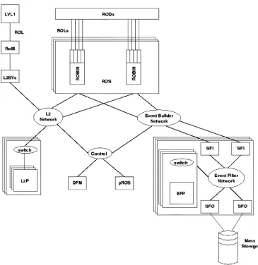
Fig. 2. Baseline implementation of the data flow and HLT systems. Networks and switches around the respective subsystems are represented by bubbles (L2N – the Level 2 Network, EBN – the event builder network, EFN – the event filter network and SW, minor switches) while processors as boxes.
lection algorithms request data from variable number of RoIs, typically 1 or 2. The average spans .
It is expected that the average processing time per event to be at most 10 ms 0. This will require 500 dual-CPU processing nodes. At this configuration each node should deliver a trigger decision at a rate of , requiring an input bandwidth of
.
The last trigger level is the event filter (EF). After a LVL2 accept, the full event data is assembled and redirected into spe-cialized processing farms, where elaborated filtering algorithms are applied. This level will still reduce the trigger rate to no more than . If the event is accepted, it is recorded to perma-nent storage for later off-line analysis.
II. THESECONDLEVELTRIGGER
The LVL2 system is part of the ATLAS data flow [3] as illus-trated in Fig. 2. The main components are the readout system (ROS), the LVL2 system, the event builder (EB) and the EF.
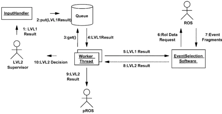
Data for events accepted by the LVL1 trigger are sent to the ROSs and, in parallel, information on the location of RoIs iden-tified by LVL1 is sent to the LVL2 supervisor. The LVL2 super-visor sends the LVL1 Result to a LVL2 Processor (L2P), where
the event selection is performed. Using the LVL1 Result as guid-ance, specialized LVL2 algorithms request a subset of the event data from the ROSs to perform the selection. This task consists of determining if the event generated by the LHC contains char-acteristics classifying it as an event of interest through energy sums, particle shower containment, track-finding and track-fit-ting algorithms among other methods [2]. For events accepted by LVL2, details are sent to a “pseudo” ROS (pROS) to be in-cluded in the event. The L2P sends the LVL2 Decision back to the LVL2 supervisor (L2SV), which forward it to the EB.
A. The Event Processing Framework
The LVL2 components are applications based on the ATLAS data flow framework that provides a set of tools that enable these applications to exchange event data, to be remotely con-trolled, to report messages and to be monitored. Applications in this framework exchange data through a set of predefined mes-sages that may run over standard TCP/IP, UDP, or raw Ethernet. Both the framework and the applications are designed using ob-ject-oriented techniques [4] and fully implemented in C++.
DOS ANJOSet al.: SECOND LEVEL TRIGGER OF ATLAS EXPERIMENT AT CERN’SLHC 911
Fig. 3. UML collaboration diagram of the application running on the L2P.
event. The synchronization mechanism between the input and the workers is an event queue, which is protected against con-current access. Each worker, after extracting one LVL1 result out of the input queue, will start the event selection chain.
The L2P tasks, including workers, have been implemented as threads. This approach is interesting because symmetric multi-processor architectures, computers with multiple multi-processors of the same type sharing a common memory bank, can be more ef-ficiently exploited to achieve the required LVL2 trigger rate at a reduced cost with a smaller farm as opposed to a process-based approach. In addition, the L2PU becomes insensitive to laten-cies as the ESS may run in one thread whilst waiting for data in another thread.
Multithreading imposes a few restrictions to the software that runs concurrently. Initially it needs to be made thread-safe, which means that concurrent write access to globally visible variables should be protected by process locks. Software that runs in multiple threads of execution also needs to be made thread-efficient which means that the number of locks should be minimized to avoid thread inter-locking. Excessive locking may slow down the processing considerably by enforcing sequential execution of large parts of the threads.
It is by far not evident to make C++ code thread-safe and even less to make it thread-efficient. For example, by using the latest GNU C++ compiler, locks are systematically used in memory allocators for standard container objects. Naive use of lists, maps or even vectors in parallel threads of execution may considerably reduce the performance of applications. The so-lution here is to change the standard memory allocator by an allocator without locks. However, this method will fail when li-braries pre-compiled with standard allocators are used.
The ESS is dynamically loaded. It is developed in an off-line framework, restricted to use only services also available on-line and respecting the programming guidelines implied by the L2P application design. Many of the existing off-line tools available are also implanted into the application running at an L2P [5]. For testing, there is also a possibility to emulate the complex ESS. Measurements presented below were made with the dummy ver-sion of the ESS. The dummy ESS implementation emulates data processing, including the multistep analysis and data requests.
III. MEASUREMENTS
A. Critical Parameters of the Readout System
Some measurements varying parameters that are critical for the performance of the RoI data collection have been made. Though the number and average size of the RoIs depend on physics, the ROB concentration factor (the number of ROBs contained within one ROS which may be read in one opera-tion) is a parameter that may be chosen to optimize the readout. The optimum number of parallel worker threads depends on the number of CPUs in one node and the idle time incurred when waiting for ROSs to send their data. The latter depends obvi-ously on the size of the RoI as well as the ROB concentration factor. In the following measurements, the L2P collects only the RoI data, i.e., it does not execute any LVL2 algorithm.
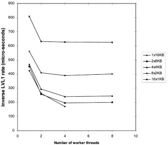
The contribution of RoI data collection to the L2P event pro-cessing time as a function of the RoI size and the number of ROSs over which the RoI is distributed is shown in Fig. 4. The range of measurements presented in this figure corresponds to the currently expected RoI sizes and their distribution over ROBs, e.g., an RoI in the Liquid Argon (the electromag-netic ATLAS calorimeter section) detector is expected to be dis-tributed over 13 to 16 ROBs [2] and have a size of approximately 16 kB. It can be observed from these results that the time taken to collect RoI data contributes, in the worst case, to less than 10% to the average event processing time budget.
912 IEEE TRANSACTIONS ON NUCLEAR SCIENCE, VOL. 51, NO. 3, JUNE 2004
Fig. 4. Summary of the performance of the RoI data collection for various combinations of RoI sizes (in bytes) and worker threads. The plot shows the inverse of the input L2SV rate as a function of the number of ROSs that contributes with RoI data.
[image:4.612.130.467.443.734.2]DOS ANJOSet al.: SECOND LEVEL TRIGGER OF ATLAS EXPERIMENT AT CERN’SLHC 913
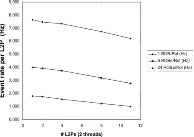
Fig. 6. Event rate per L2P as a function of the number of L2Ps in the system for a different number of ROBs per RoI. Each ROB contributes with an equal amount of data for the RoI in every test.
Fig. 7. L2SV sustained LVL1 accept rate versus the number of L2PUs.
B. Scalability
The measurements so far presented have shown the rate at which a single L2P, with a dummy ESS, can collect RoI data. The achieved performance depends on the RoI size, the ROB concentration factor and the number of worker threads. For the system, however, it is also necessary to demonstrate that when many L2Ps are requesting data at the same time from the same set of ROSs the performance of the RoI collection does not de-grade unacceptably.
For this test, L2Ps with dummy ESS were again used, al-though it should be noted that the request rate for data per L2P is much higher that it would be if the real classification algorithms were included. Thus, in these measurements, each L2P gener-ates more than ten times the normal request rate. Similarly, the requests are sent to a small number of ROSs due to machinery availability, so that again it is important to ensure that the total request rate did not exceed the capability of these components. The tests were run in a testbed consisting of three L2SVs, four ROSs and up to eleven L2Ps. All the nodes in this testbed were
[image:5.612.125.468.332.484.2]914 IEEE TRANSACTIONS ON NUCLEAR SCIENCE, VOL. 51, NO. 3, JUNE 2004
seems reasonable to assume that with more typical conditions a full-sized system will show acceptable scaling. This interpre-tation is reinforced by the fact that running similar tests with the ROSs replaced by custom hardware ROS emulators shows scaling within better than 10% over the same range of RoI data traffic.
Fig. 7 shows the LVL1 rate sustained by the L2SV as a func-tion of the number of L2Ps that it controls. In this measurement the computer running the L2SV is also connected to a gigabit Ethernet switch on which a number of PCs are also connected, each of which were executing the L2P code equipped with a dummy ESS. The L2SV was not connected to the LVL1 proto-type; instead it emulated the receiving of events from this sub-system. As can be seen from the figure, the L2SV can sustain a LVL1 accept rate of 32 kHz when distributing RoI information to a single L2PU and the dependency on the number of L2PUs is 1%. Thus, based on today’s prototype implementation and PCs, ten L2SVs are sufficient to support a LVL1 accept rate of 100 kHz.
IV. CONCLUSION
We have presented a LVL2 system that uses a farm of con-ventional PCs running ESS guided by results from the LVL1 trigger. Standard Gigabit Ethernet is used to connect the indi-vidual processors to the readout system. All measurements were made using a connection-less protocol, UDP, or raw Ethernet. Although not explicitly shown in the measurements, the perfor-mance differences were minimal.
It has been shown that the I/O capacity of each node is largely sufficient. The CPU resources devoted to RoI data collection
use a modest fraction of the allocated time budget for a large range of RoI sizes. Though concentration of multiple ROBs in one ROS (resulting in the transfer of larger data slices if the ROB to detector mapping is optimized) is more efficient, even an architecture with a concentration factor of one would still give acceptable results.
Event parallelism using multiple threads is effective, al-lowing the use of multi CPU nodes to save on cost, cooling and floor space. Additional threads are necessary to compensate the readout latency.
The scalability has been measured for a system with a small number of nodes. It has been shown that, with unrealistically high data rates into each processor and a small number of ROSs, LVL2 rates as high as 70 kHz can be obtained with a relatively modest fall of scaling.
REFERENCES
[1] “ATLAS: Technical Proposal for a General-Purpose pp Experiment at the Large Hadron Collider at CERN,” ATLAS Collaboration, European Centre for Particle Physics, CERN, Geneva, Switzerland, CERN/LHCC/94–43, 1994.
[2] (2003) ATLAS High-Level Triggers, DAQ and DCS Technical De-sign Report. ATLAS Trigger and Data Acquisition Collaboration, Euro-pean Centre for Particle Physics, CERN, Geneva, Switzerland. [Online]. Available: http://cern.ch/atlas-proj-hltdaqdcs-tdr
[3] M. Abolinset al., “The baseline dataflow system of the ATLAS trigger and DAQ,” presented at the 9th Workshop Electronics for LHC Experi-ments, Amsterdam, The Netherlands, Oct. 2003.
[4] S. Gadomskiet al., “Experience with multi-threaded C++ applications in the ATLAS dataflow software,” presented at the Computing in High-Energy Physics, La Jolla, CA, Mar. 2003.