Demand Side Management using Electric Springs
B S Srikanthan1, Sagar Deshpande2 1
Associate Professor, NIE Institute of Technology, Mysuru 2
Research Scholar, Visvesvaraya Technological University, Belagavibssrikanthan [at] gmail [dot] com, sagariniisc[at] gmail [dot] com
Abstract: In the present trend, the power system is facing the problem of effective loss minimization which is to be addressed through appropriate control techniques. However, it is evident from the survey on the distribution networks that not much of effort has been put to improvise the throughput affecting factors like Voltage regulation, Loss Management, Power Factor, Frequency control etc., The primary focus of the work proposed is to regulate the voltage across the critical and non-critical loads through demand side management. In the pervasive approach STATCOMs, SVCs, UPFC have been efficient towards achieving the voltage control, in addition to this the inclusion of Electric Springs has been a significant development which has better throughput in terms of voltage control. Comparative analysis of the regulation of voltage for various loads has provided standard set of results which can be used to balance the load losses in the distribution network. With this approach of modelling electric springs which will account for the demand side management in distribution network integrated with renewable energy sources. The simulation results in comparison with the experimental results clearly indicate the efficacy of employing electric springs in distribution system thereby increasing the throughput.
Keywords: Electric springs, STATCOM, SVC, UPFC, Voltage control, Voltage regulation.
I. INTRODUCTION
Across the globe creating the sustainable environment, by increasing the dependency for power on Renewable Energy Sources (RES) such as wind , solar etc. [1]. With abundance of high rise buildings, Singapore plans to implement large-scale solar test beds in 30 precincts, and reduce its energy intensity (per dollar GDP) by 35% from 2005 levels by 2030[2, 3]. USA also plans to increase share of renewable energy to 20% by 2020 [4]. Unpredictable and intermittent nature of RES along with their expected high penetration in grids and microgrids may pose problems of voltage instability.
A new concept of Electric Spring (ES) was introduced in[5, 6] to provide dynamic voltage regulation. A paradigm shift in reactive power compensation was implemented with “input-feedback and input voltage control” compared to the traditional aspect of “output-feedback and output voltage control”. It was demonstrated in [7] that the energy storage requirements were reduced in former scheme in comparison to the latter. The authors also proposed embedding of ES in existing non-critical loads, such as electric heaters, so as to develop smart loads to dynamically regulate power to critical loads. With buildings using around 40% of total electricity in many countries and to reduce their energy footprint, they seem a logical focus point to incorporate electric springs [8, 9]. As air conditioning accounts for 50% of energy usage in a building, the central air conditioning system can be used as a non-critical load for a whole commercial building. To augment the existing research, an Electric Spring implemented through a full bridge pulse width modulation (PWM) based inverter is proposed and explained in Section III. Further, it is tested on MATLAB® Simulink platform and demonstrated how an ES can help in shaping reactive and active power and provide instantaneous voltage support in Section IV. The ES is attached to a substantial single non-critical load, like central air-conditioning system, so to create smart load which follow renewable power generation. Such a system can be attached directly to existing facilities without encroaching on costumer comfort.
II. PRINCIPLE OF DEMAND SIDE MANAGEMENT
A. Hooke’s Law in the Mechanical Domain
The Hooke’s law published in 1660 provides the relationships of the force and displacement as follows: F = - kx (1)
where F is the force vector, k is the spring constant and x is the displacement vector. The potential energy (PE) stored in the mechanical spring is:
PE = ½* kx2 (2)
robust support system, because the overall system is highly stable even if some individual springs fail. Such concept can be adopted in taming the intermittent nature of wind and solar power generation in future power grid.
B. Hooke’s Law in the Electric Domain – Electric Spring
An ES is analogous to a mechanical spring that it can be used to (i) provide electric voltage support, (ii) store electric energy and (iii) stabilize system operation [15][16]. Analogous to (1), the basic physical relationship of the electric spring is expressed as:
q = −Cva (3)
where q is the electric charge stored in a capacitor with capacitance C, va is the electric potential difference across the capacitor and ic is the current flowing into the capacitor. The energy storage capability of the ES can be seen from the potential electric energy stored in the capacitor:
PE=1/2*C*va2 (4)
III.PRACTICAL IMPLEMENTATION AND CHARACTERISTICS OF ELECTRIC SPRING
In electrical engineering term, this electric spring is a special form of reactive power controller. In the last two decades, power electronics based reactive power controllers (RPC) have been developed in power industry to control power flow in high voltage transmission lines [8]–[17] and for dimming lighting systems [18], [19]. Their simplified control schematics are illustrated in Fig. 2(a) and 1(b), respectively. In these applications [8]–[19] of series RPC, the input of the RPC is always vs and the output vo is regulated to a constant level (i.e., a traditional “output-feedback and output-voltage control” of is adopted). It is important to note that the electric spring differentiates itself from previous use of RPC with the adoption of an “input-feedback and input-voltage control” as shown in Fig. 2(c). By regulating the input voltage vs and letting the output voltage vo to fluctuate dynamically (i.e., a new input-voltage control), such RPC would: i) provide the voltage support as an electric spring and ii) simultaneously shape the load power to follow the available power generated by renewable energy source. Such subtle change in the control strategy of a RPC from output control to input control offers new features and functions for power and voltage control [26]. This new discovery provides the opportunity to apply the electric spring for balancing the instantaneous power of the load demand and the generated power [20], [21] for future smart grids with substantial renewable energy sources.
For a load that can be divided into two parts: a noncritical load
Z1and a critical load Z2 , as in Fig.1. By connecting an electric spring in series with the noncritical load, we can ensure that the
voltage and power at the critical load to remain constant when the line voltage feeding the load fluctuates. Such an arrangement of load will be called “smart load.” The aim of the electric spring in the application example of Fig. 1 is to restore vs to the nominal value of the mains voltage vs_ref at the location of the device installation. Let Pin be the dynamically-changing input power. The general power balance equation for the system in Fig. 4 is
(5)
Where vo and vs are the root-mean-square values of the noncritical load voltage and the ac mains voltage, respectively; Re(Z) is the real part of that represents the resistive element R. Z1 is the impedance of the “noncritical” load and is the impedance of the “critical” load.
Fig.2. (a) Simplified control schematic of series reactive power compensator
for output voltage support in transmission ( vo regulated) [9]–[15]. (b) simplified control schematic of series reactive power compensator as a central dimming systems (vo regulated) [18], [19]. (c) Simplified control schematic of series reactive power compensator as an electric spring ( regulated).
The vector equation for the electric spring is
(6)
be reduced and so the power consumption of Z1 will also be reduced. Therefore, if the electric spring performs well, P2 for the critical load should remain constant as expected and P1 for the noncritical load should follow the power generation profile.
IV. PRACTICAL EVALUATION
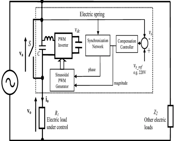
[image:5.612.155.462.250.496.2]In order to practically evaluate the performance and operating modes of the proposed electric springs, 3 different experiments have been set up at the Maurice Hancock Smart Energy Laboratory at Imperial College. a) The first test is to power the electric spring with its series-connected electric load using a standard ac power source so that the performance of each operating mode can be examined. The electric spring voltage and current are measured under the three operating modes. b) The second test is to program the electric spring with power reduction function and test it in the setup of Fig. 1. An unstable power source is created in the form of a wind power simulator, which is formed by generating electric power by a power inverter following a prerecorded wind speed profile and a base power profile of the ac generator. The purpose is to check the voltage support capability of the electric springs and also the relationship of the intermittent renewable power (from the wind power simulator) and the load consumptions in the noncritical and critical loads. c) The last test is to check the performance of the electric spring in a power system.
Fig.3. The experimental setup for the electric spring (with control block diagram).
A. Operation of an Electric Spring as a Novel Smart-GridDevice
Fig. 3 shows the practical setup of the first test. Using the input voltage control method, the voltage error is fed to a compensation controller which generates the magnitude control signal for the sinusoidal PWM generator. Via a synchronization network, a phase control signal is also fed to the sinusoidal PWM generator, which in turn provides the gating signals for the power inverter. The PWM voltage output of the inverter is filtered by the low-pass LC filter so that the electric spring voltage is sinusoidal. The phase control signal ensures that the electric spring current is either leading or lagging the electric spring voltage by 90. The test conditions are Vs=220V (50Hz), R1=51.4Ω. When the electric spring (ES) is operated near the neutral position, the measured
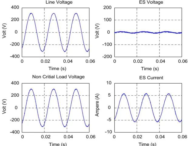
Fig. 4. Measured steady-state electric spring waveforms under “neutral” mode. Va=4.5 Vac, Qes=17.5 Var
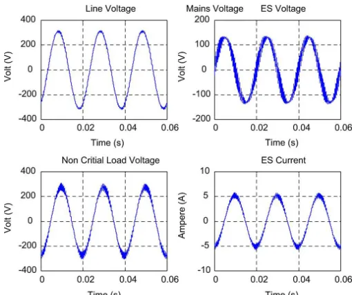
Fig. 6. Measured steady-state electric spring waveforms under “ inductive”mode. Va=94.3Vac,Qes=348.9Var.
B. Test of Electric Spring in a Power System With Intermittent Renewable Power Injection
A smart load unit comprising a combination of resistors (representing water heaters) has been setup. Two power sources separated by a transmission network box are used in this test. The experimental setup is shown in Fig. 7. An ac voltage source (provided by a 90 kVA sinusoidal PWM power inverter) and an intermittent renewable voltage source (provided by a 10 kVA power inverter) are used together to simulate the situation when intermittent renewable power becomes a substantial portion of the total power generation. In order to simulate the wind power generation, a recorded wind profile is used for the power inverter to generate the wind power. Since the electric spring is tested in the distribution network the choice of the line impedance to resistance (X/R) ratio should reflect the value used for distribution cables. For distribution lines, the typical ratio of reactance and resistance (X/R) is typically in the range from 2 to 8 [28]. It should be noted that the cables under consideration are those used in the overhead cables linking houses from one to the other in streets (e.g in the distribution network of the residential area in Australia). For a modest 150 A (240 V) overhead distribution copper cable, a typical phase size of 500 should be chosen. According to [29], copper cable with a phase size of 500 has a line impedance of 0.1020Ω and resistance of 0.0348Ω per 1000ft.The X/R ratio is about 4.87 (which is
[image:7.612.178.433.87.301.2]within the typical range of 2 to 8 for a distribution cable). In this test, the two transmission network boxes have X/R ratios of 7.5 and 3.8 respectively. These ratios are within the typical range for distribution cables in [28]. A prerecorded wind profile of 12 min (720 s) is fed to a power inverter to generate a weakly regulated ac mains voltage pattern in the bus bar. Both the smart load and the critical load are connected across the power lines. The same 12-min wind-driven voltage pattern was repeated from 720 s to 1440 s. The electric spring of the smart load is deactivated in the first voltage pattern by closing the bypass switch and then activated in the second pattern with open.
Fig. 8. Measured root-mean-square values of the critical load (mains) voltage , noncritical load load voltage vo and electric spring voltage va before and after the electric spring is activated.
Fig. 9.Measured power of the critical load and smart load.
Fig. 8 shows the measurements of the (scalar) rms values of the critical load (mains) voltage vo , the noncritical load voltage and the voltage of the electric spring va before and after the electric spring is activated. Before the electric spring takes action in the first half of the test, the mains voltage fluctuates in the region below and above the rated value of 220 V. Because the bypass switch is closed when the electric spring is deactivated, the noncritical load voltage vo overlaps with the unstable mains voltage vs in the first voltage pattern generated by the wind power simulator. However, it can be seen that, when the electric spring is activated in the repeated voltage pattern in the second half of the test, the mains voltage can be successfully regulated to 220 V. The bouncing action of the electric spring voltage can be seen from Fig. 9. It is noted that the noncritical load voltage vo is reduced when the electric spring generates positive or negative voltage to regulate the mains voltage. The consequential variation of vo provides an automatic noncritical load power shedding and generates reactive power to follow the dynamic changes of the wind power profile. This effect can be observed from the practical power measurements of the smart load unit in Fig. 18. After the electric spring is activated, the load demand of the noncritical load is shed and the reactive power is generated to follow the unstable mains voltage whilst the demand of critical loads remains essentially the same. This result demonstrates the effectiveness of the electric spring in both voltage regulation and shaping the load demand to follow the
wind power. These measurements confirm the scientific theory and the effectiveness of the electric spring in regulating the mains voltage of an unstable power system and in balancing the wind power and the load power dynamically.
V. CONCLUSION
The Hooke’s law on mechanical springs has been developed into an electric spring concept with new scientific applications for modern society. The scientific principles, operating modes
[image:8.612.181.432.238.374.2]springs will provide a highly reliable and effective solution for distributed energy storage, voltage regulation and damping functions for future power systems. Such stability measures are also independent
of information and communication technology (ICT).
This discovery based on the three-century-old Hooke’s law offers a practical solution to the new control paradigm that the load demand should follow the power generation in future power grid with substantial renewable energy sources. Unlike traditional reactive power compensation methods, electric springs offer both reactive power compensation and real power variation in the noncritical loads. With many countries determined to de-carbonize electric power generation for reducing global warming by increasing renewable energy up to 20% of the total electrical power output by 2020 [22]–[25], electric spring is a novel concept that enables human society to use renewable energy as nature provides. The Hooke’s law developed in the 17th century has laid down the foundation for stability control of renewable power systems in the 21st century.
REFERENCES
[1] Van drongelen, b. Roszek, e. S. M. Hilbers-modderman,m. Kallewaard, and c. Wassenaar, “wheelchair incidents,” rijksinstituutvoorvolksgezondheid en milieu rivm, bilthoven, nl, tech. Rep.,november 2002, accessed februaury,2010
[2] A. Frank, j. Ward, n. Orwell, c. Mccullagh, and m. Belcher, “introduction of a new nhs electric-powered indoor/outdoor chair (epioc) service: benefits, risks and implications for prescribers,” clinical rehabilitation, no. 14, pp. 665–673, 2000.
[3] R. C. Simpson, e. F. Lopresti, and r. A. Cooper, “how many people would benefit from a smart wheelchair?” Journal of rehabilitation research and development, vol. 45, no. 1, pp. 53–71, 2008
[4] T. Carlson and y. Demiris, “collaborative control for a robotic wheelchair: evaluation of performance, attention, and workload,” ieee transactions on systems, man, and cybernetics, part b: cybernetics,vol. 42, no. 3, pp. 876–888, 2012.
[5] B. Rebsamen, c. Guan, h. Zhang, c. Wang, c. Teo, m. Ang, and e. Burdet, “a brain controlled wheelchair to navigate in familiar environments,” ieee transactions on neural systems and rehabilitation engineering, vol. 18, no. 6, pp. 590–598, dec. 2010.
[6] I. Iturrate, j. Antelis, a. K¨ubler, and j. Minguez, “a noninvasive brainactuated wheelchair based on a p300 neurophysiological protocol and automated navigation,” ieee transactions on robotics, vol. 25, no. 3,pp. 614–627, june 2009.
[7] J. D. R. Mill´an, f. Gal´an, d. Vanhooydonck, e. Lew, j. Philips, and m. Nuttin, “asynchronous non-invasive brain-actuated control of an intelligent wheelchair,” in proc. 31st annual int. Conf. Ieeeeng.Med.biol. Soc., 2009, pp. 3361–3364.
[8] J. D. R. Mill´an, f. Renkens, j. Mouri˜no, and w. Gerstner, “noninvasive brain-actuated control of a mobile robot by human eeg,” ieee trans biomed eng, vol. 51, no. 6, pp. 1026–1033, 2004.
[9] F. Gal´an, p. W. Ferrez, f. Oliva, j. Gu`ardia, and j. D. R. Mill´an, “feature extraction for multi-class bci using canonical variates analysis,” in ieeeintsymp intelligent signal processing, 2007.
[10] J. D. R. Millan, p. W. Ferrez, f. Galan, e. Lew, and r. Chavarriaga,“non-invasive brain-machine interaction,” int j pattern recognition and artificial intelligence, vol. 22, no. 5, pp. 959–972, 2008.
[11] S. Perdikis, h. Bayati, r. Leeb, and j. D. R. Millan, “evidence accumulation in asynchronous bci,” international journal of bioelectromagnetism, vol. 13, no. 3, pp. 131–132, 2011.
[12] G. Lucas, “a tutorial and elementary trajectory model for the differential steering system of robot wheel actuators,” the rossum project, tech. Rep., may 2000. [13] E. Fazl-ersi and j. Tsotsos, “region classification for robust floor detection in indoor environments,” in image analysis and recognition,m. Kamel and a.
Campilho, eds. Springer berlin / heidelberg, 2009,vol. 5627, pp. 717–726.
[14] T. Dutta and g. Fernie, “utilization of ultrasound sensors for anticollision systems of powered wheelchairs,” ieee transactions on neural systems and rehabilitation engineering, vol. 13, no. 1, pp. 24–32,march 2005.
[15] S. Beucher, “the watershed transformation applied to image segmentation,”scanning microscopy international, vol. 6, pp. 299–314, 1992.
[16] J. Borenstein and y. Koren, “the vector field histogram - fast obstacle avoidance for mobile robots,” ieee transactions on robotics and automation, vol. 7, no. 3, pp. 278–288, 1991.
[17] G. Schioner, m. Dose, and c. Engels, “dynamics of behavior: theory and applications for autonomous robot architectures,” robot. Autonomous syst., vol. 16, pp. 213 – 245, 1995.
[18] L. Tonin, t. Carlson, r. Leeb, and j. D. R. Millian, brain-controlled telepresence robot by motor-disabled people,” in proc. Annual international conference of the ieee engineering in medicine and biology society embc 2011, 2011, pp. 4227–4230.
[19] S. Ten hagen and b. Krose, “trajectory reconstruction for self localization and map building,” in proceedings of the ieee international conference on robotics and automation, vol. 2, 2002, pp. 1796 – 1801 vol.2.
[20] D. Norman, the design of everyday things. Doubleday business,2002.
[21] T. Shimakage et al., “supply and demand control of distributed generators in a microgrid,” in proc. Ieeeintelec, 2008, pp. 1–5. [22] “meeting the energy challenge: a white paper on energy,” may 2007 [online]. Available: http://www.berr.gov.uk/files/file39387.pdf
[23] “china eyes 20% renewable energy by 2020,” china daily, 2009.on investing in the development of low carbon technologies (setplan) a technology roadmap,” commission of the european communities, brussels, belgium, 2009.
[24] “proposal for a directive of the european parliament and of thecouncil on the promotion of the use of energy from renewable sources,” com:2008:0019:fin:en:pdf, 2008
[25] S. Y. R. Hui, c. K. Lee, and f. F. Wu, “power control circuit and method for stabilizing a power supply,” u.s., pct patent application 61/389,489, oct. 4, 2010. [26] C. K. Lee, s. N. Li, and s. Y. R. Hui, “a design methodology for smart led lighting systems powered by weakly