©IJRASET 2015: All Rights are Reserved
880
Kinematic Analysis and Design Optimization
of Rear Suspension of an ATV
Nikhil Bakal1, Mohak Samant2, Juzer Kothawala 3, Prof Ravi K4 .
1,2,3
M. Tech Automotive engineering, 4Assistant Professor, Thermal and Automotive Division, School of Mechanical and Building sciences, VIT University –Vellore (632014), Tamil Nadu-India
Abstract—The objective of this work is to design and analyse the rear suspension of an All Terrain Vehicle. Suspension kinematics are designed for a mini BAJA ATV used in racing using multi body dynamics approach in LOTUS SHARK software. Modifications are done on the current geometry which is a semi trailing arm suspension and rear links are added to increase the adjustability as well reduce the variation of camber, toe, half track width and roll center height. By altering the design the drive shaft articulation limits are achieved which protects the universal joints from damage. By minimizing the variation in toe and camber angle the straight ahead tendency of the car increases also reducing the tire wear on different terrains during the race. The reduction in the variation of half track width and roll center height increases the stability of the vehicle during sharp maneuvers and uneven terrain thus increasing the stability of vehicle.
Keywords— All Terrain Vehicles, SAE BAJA, Multi- Body Dynamics, LOTUS SHARK, Semi-trailing arm suspension.
I. INTRODUCTION
All Terrain Vehicles (ATV) are off-road vehicles which are capable of driving on and off paved or gravel surface and handle a wider variety of terrain than most other vehicles. Suspension and chassis play a vital role in the structural performance of an off-road vehicle. The racing vehicle is a Baja off-off-road prototype which is used in the BAJA SAE India competition among universities with top speeds reaching unto 45- 65km/hour. The racing event consists of a manuverability test, endurance test and hill climb test which have to be performed on different road conditions such as muddy, soft soil and loose gravel. In these tests the vehicle suspension system must withstand sharp hairpin bends (cornering), undulating track conditions which includes a series of crest and troughs without losing road holding capability. The driver has to safely overcome these severe conditions without compensating speed. The work will focus on Computer Aided modelling and simulation of rear suspensions of SAE Baja vehicle to improve suspension properties such as roll centre height, camber angle, toe angle and compliance of drive shaft articulation with road bump. The vehicle under study is VIT SAE BAJA all terrain vehicle, particularly the rear suspension. Currently, team “Kshatriya” (VIT SAE BAJA) uses a semi trailing link type rear suspension with side thrust member attached in between trailing arm and the chassis. This geometry has certain drawbacks such as very high camber change in bump travel as well as tendency of wheels to toe out during cornering. As the numbers of links are increased, more flexibility in adjustment of toe angle and camber angle can be achieved without causing major design changes to the suspension. To verify proposed solution, a Multi Body Dynamic (MBD) model of the ATV suspension system will be built using LOTUS SHARK suspension software. The research will focus on minimizing roll centre height, camber and toe angle variation, thus increasing the road holding capability of the vehicle under cornering and race track conditions. These characteristics will be studied by software simulation of various tests on the rear suspension of the vehicle which includes “parallel wheel travel analysis” which simulates bump travel. From these tests the topological factors (hard points) of the suspension which highly influence the stability of the vehicle will be determined and the position of these hard points will optimized for obtaining the desired results .This approach provides a viable alternative to costlier active control systems for vehicles. Sahil Kakria et. al(1), created a Multi body dynamics model of Baja ATV suspension system in ADAMS/Car. They have studied the effect of change in A arm suspension hard points on suspension characteristics such as camber angle, toe, castor, kingpin inclination etc, by simulating various tests and optimized them using Adams Insight. Diego David Silva diniz et al(2), have performed a similar analysis using MBD approach on the rear suspension assembly of an off-road vehicle and have obtained an optimal position of the connection point of the guiding bar arm and chassis which provided the required over steer characteristics while retaining advantages of Double A arm suspension. Yung Chang Chen et.al(3), have analysed a SLA double wishbone suspension for its ride, handling and suspension roll characteristics analysis, using MSC Adams software. They have concluded that the SLA suspension had larger roll centre height which reduces the roll effect. Toe out caused bump oversteer while the camber angle and track width variation were found to be acceptable.
©IJRASET 2015: All Rights are Reserved
881
The influence of suspension kinematics on the handling performance of the vehicle is studied using certain parameters such as toe, camber, roll centre height and half track width.
A. Half Track Width
Due to lateral compliance of tires and suspension, as well as changes in wheel lateral location due to suspension kinematics and changes in camber angle, the distance in lateral direction between the center line of vehicle and the tire contact patches changes. If there is change in the half-track width during cornering with additional effects due to bumps and pits the vehicle becomes unstable and can roll over. SSF = tw/(2ho) is defined as the static stability factor, where tw/2is the half-track width and ho is the
roll center height.Variation of wheel track along with wheel travel reflects the wearing condition of the tire on the sides. As the variation increases the tire wear increases.
B. Toe Angle
As the toe angle changes the directional stability of the vehicle is compromised. Bump steer by definition is toe angle change with suspension travel which produces a steering action. If one tire goes over a bump and experiences a toe angle change the vehicle will steer. This condition is very troublesome for the driver because the driver will consistently have to correct the vehicle as the vehicle travels over changes in road conditions. Hence toe angle variation should be as less as possible to avoid unpredictable understeer and oversteer characteristics.
C. Camber
When wheels travel up and down, the wheel centre traverses a curve and this causes the suspension links to be dragged laterally outboard or inboard this causes a scrubbing action at the tire contact patch increasing the tire wear. In the rear suspension CV joints are used for powering the wheels which don’t allow very large angular movement of the drive shafts which causes their limited travel, and suspension travel has to be restricted too. Thus the wheel travel is constrained by the drive shaft articulation angle limitations. This leads to a practical limit on the camber angle angle variation.
D. Roll Center Height
Roll center is the point at which the lateral forces generated at the tire contact patch are transferred from the unsprung mass to the sprung mass. Its height above the road surface is known as the roll center height. As the roll center height variation decreases, the roll over tendency of the vehicle also decreases.
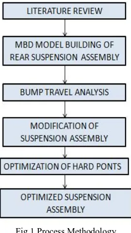
III. METHODOLOGY
[image:3.612.243.378.448.688.2]The process methodology is given in figure 1.
Fig 1.Process Methodology
©IJRASET 2015: All Rights are Reserved
882
Fig 2. Semi – Trailing arm suspension
[image:4.612.237.372.288.388.2]Absolute values and trends of the suspension kinematics have been extracted by carrying out a parallel wheel travel analysis .Then a modified suspension assembly consisting of a semi trailing arm with upper and lower rear links attached from the knuckle onto the body was devised as shown in fig 3.
Fig 3. Modified Suspension Assembly
The new assembly is built using the template builder module in lotus shark. The new design increases the flexibility of the earlier semitrailing arm suspension system. These links are connected with the help of ball joints both at the body and knuckle end. The spring stiffness is same as the earlier design used i.e. 50 KN/m and a FOX make gas filled shock absorber having damping coefficient of 3Ns/m was used. The hard points of the new design the suspension are varied using an approximation and the effects on camber, toe, half track width and roll centre height variation are analysed. Best possible solution where camber and toe change variation is the least possible is chosen.
IV. RESULTSANDDISCUSSION
During cornering manoeuvres, due to lateral load transfer there is more load on the outer wheels. In order to ensure stability, a larger contact patch is required which is possible with minimum camber angle variation during wheel travel in bump and jounce. Therefore, the camber angle variation during suspension travel has been reduced from around 7.50 to less than 1° which helps in maintaining adequate contact with the ground and also helps to reduce tire wear. The graph of camber angle for the semi-trailing arm and modified suspension is shown in Fig. 4.
Fig 4. Variation of Camber Angle with wheel travel
[image:4.612.233.385.572.675.2]©IJRASET 2015: All Rights are Reserved
883
Fig 5.Variation of Toe angle with wheel travel.
[image:5.612.226.389.299.419.2]The wheel track variation during suspension travel can be conveniently represented by the half wheel track variation. As can be seen from fig . 6, The wheel track variation has been reduced from 30mm for semi-trailing suspension to less than 10mm for the modified suspension assembly. This helps in reducing the scrubbing of the tire in the lateral direction while in wheel travel. This reduces excessive wear of the tire and also helps in minimizing toe angle variation during wheel travel.
Fig. 6. Variation of Half wheel track with wheel travel
For maintaining stability of the vehicle while encountering various obstacles such as bumps and droops during the race, and preventing the vehicle from roll over it is very essential to maintain a constant roll centre height or maintain the vertical position of the roll centre with very less variation. This was checked for the given semi-trailing suspension by means of a parallel wheel travel analysis and it was found to be 100mm. But with the modified suspension design the variation is reduced to 20mm as can be seen from fig. 7.
Fig. 7.Variation of Roll Centre height with wheel travel analysis
V. CONCLUSION
[image:5.612.237.375.506.637.2]©IJRASET 2015: All Rights are Reserved
884
parameters leads to predictable and safe behavior of the BAJA car during racing which was desirable outcome.
REFERENCES
[1] Sahil Kakria, IVN Sri Harsha and Milind Wagh “Modeling and Simulation Study of BAJA SAEINDIA All Terrain Vehicle (ATV) Using Integrated
MBD-FEA Approach ” SAE Technical Paper series 2015-26-0219.
[2] Diego david, Arthur Azevedo Ferreira, Raphael de Sousa Silva, Antônio Almeida da Silva, Wanderley Ferreira “Computational analysis of a concept of
rear suspension system for off-road vehicle”, SAE technical paper series 2012-36-0425.
[3] Yung Chang Chen, Po Yi Tsai, I An Lai “Kinematic Analysis of Roll Motion for a Strut/SLA Suspension System” World Academy of Science,
Engineering and Technology, Vol:6 2012-05-21.
[4] William F. Milliken, Douglas Milliken, 1994.“Race Car Vehicle
[5] Dynamics,” SAE International.
[6] Lotus Cars Ltd. “Getting Started with Lotus Suspension Analysis,”
[7] Version 3.11.
[8] Thomas. D. Gillespie, 1992. “Fundamentals of Vehicle Dynamics,”