FPGA Implementation of 64-bit fast multiplier
using barrel shifter
Sweta Khatri1, Ghanshyam Jangid2
(Department of Electronics and Communication, Suresh Gyan Vihar University, Jaipur, Rajasthan, India.1 ,
Assistant Professor, Department of Electronics and Communication, Suresh Gyan Vihar University, Jaipur, Rajasthan, India2 )
Abstract: In this paper we have described the implementation of a 64-bit Vedic multiplier which is enhanced in terms of propagation delay when it is compared with conventional multiplier like modified booth multiplier, Wallace tree multiplier, Braun multiplier, array multiplier. We use various Vedic multiplication techniques for arithmetic operation .It has been found that the most efficient of all the sutra is Urdhva-triyagbhyam, which gives minimum delay for multiplication of all types of numbers, either small or large numbers. For ‘n’ number of shifts only one clock cycle is required in our design,using 64-bit barrel shifter. The design is implemented and verified using ISE simulator and FPGA. Synthesis report and static timing report are used for the comparison of propagation delay. The design uses barrel shifter in base selection module and multiplier which achieves propagation delay of 6.781ns.
Keywords: Barrel shifter, Base selection module, Propagation delay, Power index determinant.
INTRODUCTION
The process of computation in various digital circuits can be speed up through various arithmetic operations such as addition, subtraction and multiplication. Various processor architecture like RISC and CISC are implemented by ALU. In general, packet decimal format is used to perform arithmetic operations. It means before performing arithmetic operation, the fields are first converted to packet-decimal format, and then converted back to their specified format before placing the result in the result field.
It is proved that the most robust technique for arithmetic operations is Vedic mathematics. Vedic mathematics is an ancient and eminent approach to solve several mathematical challenges encountered in the current day scenario. Vedic mathematics was used in ancient India and was rediscovered by a famous mathematician, Sri Bharati Krishna Tirthaji. In contrast it is found that in hardware implementation of n-bit multiplier, conventional techniques for multiplication provide significant amount of delay. Moreover, the performance of multiplier is degraded by the conventional delay of the design.
Architecture selection in FPGA or ASIC mainly depends on hardware based multiplication.
In this work a high speed Vedic multiplier using barrel shifter is put into effect. Due to its feature of reducing the number of partial products, the sutra was implemented by the modified design of “Nikhilam Sutra”.The delay reduces when the barrel shifter is used at different levels of design. The delay reduces when compared to conventional multipliers. In order to achieve high outturn, we design Vedic multiplier using barrel shifter which improves the speed.
VEDIC SUTRAS
provide not only ways of thinking for their application, but also methods of calculation.
Application of the sutras ensures both speed and accuracy; based on rational and logical is used in reasoning. Application of sutras helps improve intuition that is the bottom-line of the mastery of mathematical geniuses of the past and present such as Aryabhatta, Bhaskaracharya, Srinivasa, Ramanujan. etc. This improvement occurs in the process involving rational thinking to specific problems.
The performance of multiplier was improved in proposed design but the multiplier implementation using FPGA has already been reported using different multiplier architectures. The Vedic multiplier uses modified “Nikhilam Navatascaramam Dasatah” sutra. Barrel shifter is used in [1] to modify its architecture by which significant amount of clock cycles are reduced by virtue of which the speed increases. FPGA is used to compare the performance of proposed multiplier with previously implemented multiplier.
From [5] “Vedic mathematics” is comprised of sixteen simple mathematical formulae from the Vedas. These are:
1.Ekadhikena Purvena
2.Nikhilam Navatascaramam Dasatah
3.Urdhva-triyagbhyam
4.Sunyam Samya Samuccaye
5.Anurupye-Sunyamanyat
6.Paravartya Yojayet
7.Sankalana-Uyavakalanabhyam
8.Puranapuranabhyam
9.Calana-Kalanabhyam
10.Ekanyunena Purvena
11.Anurupyena
12.Adyamadyenantya-Mantyena
13.Yavadunam Tavadunikrtya Varganca Yojayet
14.Antyayor Dasakepi
15.Antyayoreva
16.Gunita Samuccayah
“URDHVA-TRIYAGBHYAM” SUTRA
[image:3.612.28.555.374.669.2]This sutra is applicable to all multiplication operations. Its meaning is “Vertically and crosswise”. The general multiplication procedure of 4*4 multiplication is represented in fig1.The process used in the multiplication is called array multiplication technique. The technique proves efficient when the multiplier and the multiplicand lengths are small. It is not good for larger length modulation because a large amount of propagation delays are involved in these cases. Nikhilam sutra is used to overcome this problem, to calculate the multiplication of 2 large numbers. The fig. shows the method used for multiplication using “Urdhva Triyagbhyam”.
Figure 1 shows multiplication using Urdhva –Triyakbhyam algorithm
PROPOSED WORK
To derive an expression for the calculation of the product, we consider 2 input numbers A and B and the exponent of these numbers A and B are c1and c2.
The product is represented by P.
P = AB
And the input numbers are given as:
A=2c1±S1
B=2c2±S2
In the above 2 equations, S1and S2represent the residual part.
To make calculation easy, we make the bases of multiplicand and multiplier same.
Now using Nikhilam sutra,
B x 2c1-c2= 2c1±S22c1-c2
A x B x 2C1-C2= (2C1± S1) (2 C1± S
22 C1-C2
)
= 22C1 ± S12 C1±S
22
2C1-C2±S 1S22
C1-C2
=2c1(2c1±S1± S22 C1-C2
) ± S1S22 C1-C2
=2C(A±S22
C1-C2) ± S 1S22
C1-C2
P =AB=2C2 (A±S22
C1-C2) ± S 1S2
The above expression is the main equation used in the implementation. The steps used in the implementation are as follows:
Base Selection Module
Selecting of the maximum base is called base selection module. The process occurs in accordance with input numbers. The sub-module of BSM is Power index determinant (PID). Some other sub-module of BSM are:
(a)Barrel shifter
(b)Comparator
(c)Adder
(d)Mux
Process
Suppose there is an input number ‘P’ than,
P will lie in the range between 0 to n-1. The expression is given as:
P=∑( i=0 to i= n-1) Pi2 i
i.e. 2n-1≤P and P≤2n
Now the average value ‘A’ will be given as the sum of the 2n-1 and 2ndivided by 2.Finally, it is concluded that,
Base will be 2nwhen P is greater than ‘A’ and Base will be 2n when P is less then equal to ‘A’.
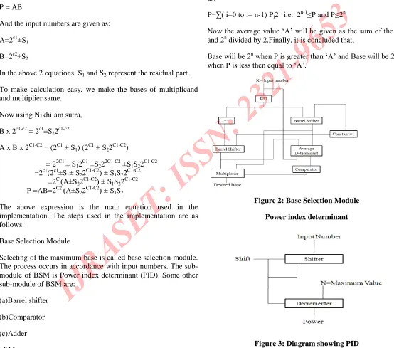
Figure 2: Base Selection Module
[image:4.612.21.575.183.672.2]Power index determinant
To compute PID we assign a pin on input bits. Starting from MSB check where the first ‘1’ comes in the input bit. If the first number is ‘0’, then go to second one. The process continues until ‘1’ is obtained. The maximum value of ‘1’ obtained from the decrementer will be the required power i.e. PID.
Structure of Multiplier
[image:5.612.296.561.112.441.2]BSM and PID combine to form multiplier structure. Equation (a) is used to find the structure. Two 8-bit numbers are sent to comparator for the process. At comparator the comparison occurs btw the numbers. From comparator the numbers are sent to BSM. The BSM is used to select the base according to the given i/p. The process continues and some of the devices are used in it such as PID, Urdhva-triyagbhyam sutra, adder and shifter.
Figure 4: Structure of multiplier
SIMULATION RESULT AND DESIGN ANALYSIS
The code utilized in this is based on VHDL i.e. Very High Definition Hardware Description Language and Xilinx-Project Navigator software with Modelsim simulator 5.4a is used for synthesis.
Waveform of 64-bit inputs
A= 0000 0000 0000 0000 0000 0000 0000 0000 0000 0000 0000 0000 0000 0000 0000 1010
B= 0000 0000 0000 0000 0000 0000 0000 0000 0000 0000 0000 0000 0000 0000 0000 1001
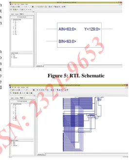
[image:5.612.26.280.321.495.2]Figure 5: RTL Schematic
Figure 6: Detailed RTL schematic
Waveform generated for 64-bit input
[image:5.612.314.548.498.643.2]CONCLUSION
In this thesis, Fast multiplier of 64-bits is implemented using barrel shifter. The coding is done in VHDL. The proposed work is done using Xilinx 9.2 simulator with 5.4a Modelsim. The hardware used for the implementation in this thesis is SPARTAN 3E 3S 250E.
The table 6.1 shown below gives the concluded result of this thesis depending on time and area parameters.
Table showing conclusion
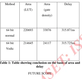
Method Area (LUT) Area (gate density) Delay 64 bit normal
220693 33076 315.871ns
64 bit
Vedic
[image:6.612.26.301.265.528.2]214645 24117 315.725ns
Table 1: Table showing conclusion on the basis of area and delay
FUTURE SCOPE
There are many applications of Vedic techniques. In this thesis we have focused more on speed and area as the Vedic techniques are faster and occupy less
space as compared to others. Future development in this proposed work is given as:
Pipelined Architecture: This architecture mainly
focuses on reduced delay and increased speed.
Use of technique in signed multiplier: Vedic
multipliers can also be used for signed numbers which reduces the problem of calculation for large numbers.
Use in Nano-technology: The work proposed in this
thesis can further be used in Nano-technology.
REFERENCES
[1] Prabir Saha, Arindam Banerjee, Partha Bhattacharyya, Anup Dandapat, “High speed ASIC design of complex multiplier using vedic mathematics” , Proceeding of the 2011 IEEE Students' Technology Symposium 14-16 January, 2011, lIT Kharagpur, pp. 237-241.
[2] Shamsiah Suhaili and Othman Sidek, “Design and implementation of reconfigurable alu on FPGA”, 3rd International Conference on Electrical & Computer Engineering ICECE 2004, 28-30 December 2004, Dhaka, Bangladesh, pp.56-59.
[3] Sumit Vaidya and Deepak Dandekar, “Delay-power performance comparison of multipliers in vlsi circuit design”, International Journal of Computer Networks & Communications (IJCNC), Vol.2, No.4, July 2010, pp.47-56.
[4] P. Mehta, and D. Gawali, "Conventional versus Vedic mathematical method for Hardware implementation of a multiplier," in Proceedings IEEE International Conference on Advances in Computing, Control, and Telecommunication Technologies, Trivandrum, Kerala, Dec. 28-29, 2009, pp. 640-642.