Technology (IJRASET)
A Distributed Generation Based Inverters for
Optimal Decentralized Voltage Control in
Distribution Systems using Fuzzy Logic Controller
U.Gajapathi1, G.Venkatpradeep2
1
PG Student, 2Assistant Professor, Dept. of Electrical & Electronics Engineering Sri Venkateswara College of Engineering &Technology,Chittoor, A.P. India
Abstract: In recent times, the penetration of Distributed Generation (DG) has been increasing rapidly. This growth of distributed electricity supply of renewable energy sources (RES) so called distributed generation (DG) can cause technical problems for electricity distribution networks like power quality problems, degradation in system reliability, reduced efficiency, over voltages and other safety issues. In this manner, the need to create appropriate control methods to permit power conveyance to clients in consistence with power quality and reliability quality guidelines (PQR) has turned into an important issue as of late. These integration problems can be overcome by reinforcing the network. This paper proposes an improved circulated control approach in view of DN affectability examination and on decentralized responsive/dynamic force control proficient of maintaining voltage levels inside administrative constrains and to offer subordinate administrations to the DN, for example, voltage control.
Index Terms:Decentralized Generation, Distributed Generation (DG, Optimal Placement of Distributed Generation (OPDG), Distribution Network, photovoltaic systems, reactive power control, voltage control, wind energy.
I. INTRODUCTION
The entrance of distributed generation (DGs) into conveyance systems (DNs) is quickly increasing over the world as of late. Different motivating force programs have energized the selection of renewable energy sources (RES) - based DGs with a specific end goal to accomplish the yearning governments targets identified with the advancement of a more manageable improvement in the energy segment. Among them, voltage rise speaks to one of the primary issues concerning DG combination into DNs, particularly on account of nonprogrammable RES-DGs (e.g., wind-or solar based ones) in feeble DNs, portrayed by a little esteem of reactance versus resistance proportion. In this manner, the need to create legitimate control systems to guarantee power conveyance to clients in consistence with PQR requirements and to furnish auxiliary administrations to the system is turning into a significant issue. It is possible to recognize two fundamental classes through the different methodologies proposed to face DGs reconciliation issues: concentrated and decentralized control techniques. The first have been broadly researched by mainstream researchers. Be that as it may, the utilization of unified control techniques to the current systems confronts a few disadvantages: in expansion to the overwhelming speculations fundamental for gadgets and control systems, all unified methodologies require an exceedingly dependable correspondence channel through the general DN. Therefore, the second classification is increasing important interest as of late.
Among decentralized methodologies, the ones confronting with DGs ability to give responsive power backing to the DN speak to a developing class of receptive dispatch innovations not yet widely explored. A standout amongst the most significant elements of this kind of methodology is to actualize the control activity at the purpose of regular coupling (PCC), permitting proficient, adaptable, what's more, and versatile control setups. An improvement method gone for minimizing power misfortunes inside the system and voltage deviation as for a reference sign is proposed for photovoltaic systems (PVs) and connected to the single feeder DN displayed.
Technology (IJRASET)
administration that grants to utilize the same nearby voltage control approach at the PCC for a DG associated with the matrix by method for electronic converters; 3) a streamlining methodology that brings together the proposed control system and the streamlining of its parameters utilized for voltage direction; and 4) a simulated insight (AI)- based enhancement method able to do avoiding neighborhood minima catching because of the non convexity nature of the issue and to confront with instabilities betterly contrasted and comparable methodologies exhibited inside the writing.
II. REACTIVE/ACTIVE POWER CAPABILITY OF INVERTER-BASED DGS
Commonly, RES-DGs are associated with the DNs by method for electronic power converters. Among the decentralized control approaches, the capacity of performing conveyed control activities considering the converters responsive and/or dynamic power
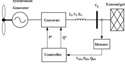
[image:3.612.195.415.230.343.2]controllable areas has as of late been explored. Such a methodology could be valuable to control voltage profiles and/or to offer auxiliary administrations to the DN, expanding dynamic power creation in the meantime.
Fig. 1. Control system structure.
All togetherto characterize the attributes of the general strategy displayed inside the paper, the structure of the proposed control system chart of an inverter based RES-DG is portrayed in Fig. 1. It speaks to the center of the OSAB-DC system and can be actualized on the on-board knowledge of every RES-DG plant associated with the DN by means of electronic converters. Also, QDG
are utilized by the OSAB-DC calculation to perform the nearby control activity.
Concerning the inverter-based DG, the converter voltage relies on upon the dc-link voltage Vc and theXc parameters of the received
regulation system. The reactance speaks to the aggregate reactance of the transformers and system channels utilized for the DG association with the DN. Beginning from the most extreme force supplied by the essential source (e.g., PV array wind turbine), the converter current and voltage limits power round limitations to the DG capacity to changeQDG and PDG.
From the conditions important to figure and it is conceivable to compose
= cos θ (1)
= ( inθ+ ) (2)
Taking into account the root mean square of the converterVc voltage as follows:
= + 2( + ) sin + ( + )
Since in all force systems applicationsXc are fundamentally more noteworthy than the DN feeder inductanceXDN, it is possible to
register the primary roundabout requirement because of the converter voltage, as expressed by the accompanying condition:
+ + ≤ (4)
With an analogous approach, it is possible to prove that the circular constraint imposed by the converter current Ic is
+ ≤( ) (5)
In order to evaluate theQDG– PDGcontrollable domain of the DG it is necessary to take into account the converter’s Vc,maxandIc,max
Technology (IJRASET)
= −
= − − (6)
For every working point, the limit of responsive power deviation accessible for the control activity must be contained inside the capacity curve characterized by
=min { , } (7)
Since the controllable space conditions basically concern the network side converter display, this methodology can be utilized for either full power consecutive converter-associated WDGs and single- or double-stage inverter-connected PVs.
Figure 2: Allowed, Operative and Control Ranges used in the proposed control method.
III. MODELLING AND CONTROL
A. PV Model
A general mathematical explanation of V-I output characteristics for a Photovoltaic cell has been studied over the past forty years. Such an equivalent circuit based model is mainly used for the MPPT technologies. The general model that which consist of a photocurrent, a diode, a parallel resistor expressing a leakage current, and a series resistor describing an internal resistance to the current flow are considered in the equivalent circuit of a PV cell[9].
The voltage current characteristic equation of a solar cell is given as:
= − .( )
. . −1 − (8)
Where, Iph is a light-generated current or photocurrent, Io is the cell saturation of dark current, k= ( 1.38 ×10⁻²³J/K) is a
Boltzmann’s constant, T is the cell’s working temperature, N is an ideal factor, Photo current mainly depend on the solar irradiance and cell’s temperature, which is described as
= ( + ∗( + 273.15− ))*G (9)
Where, Iscr is a cell’s short current at a 250c and 1kw/m2, Ki is a cell’s short circuit current temperature coefficient, Tr cell’s
reference temperature, G solar irradiance in kw/m2. Also the cell’s saturation current varies with cell temperature, which is described as
= ∗ ∗
∗
. (10)
= ( −20)∗
. + (11)
Where, I
OR is the cell reverse saturation current at a reference temperature and a solar irradiance, NOCT is a nominal operating cell
temperature. The ideality factor N dependent on PV technologies. The complete behaviour of PV cells are de-scribed by five model parameters (Iph, N, I
Technology (IJRASET)
A PV array model based on the mathematical model of solar cell is developed using MATLAB/Simulink blocks [10]. The essential input parameters such as V
m, Im, Voc, Isc, Ns, KI, Tc and G are taken from the manufacturer’s datasheet for the typical 110W modules
selected for analysis for standalone system.
The performance of solar cell is normally evaluated under the standard test condition (STC), where an average solar spectrum at AM 1.5 is used, the irradiance is normalized to 1000W/m2, and the cell temperature is defined as 25 ºC.
B. Wind Model
The aerodynamic representation of the turbine blades, generator, and converter are included in this model & simplified. A regular current source is the novel feature in which the regulated current source is represented as a single equivalent source. The rating of an individual wind turbine is considered as the size of a source.The real and reactive power of the generator can be independently controlled by injecting the set of three-phase currents into the grid. A Wind farm of rating 9MW was considered that consisting of six 1.5 MW wind turbines that are connected to a 25 kV distribution system. A doubly-fed induction generator consisting of a wound rotor induction generator is considered in the wind turbines. The stator winding is connected directly to the 50 Hz. The Doubly Fed Induction Generator technology can extract the maximum energy from the wind available for example low wind speeds by controlling the turbine speed, while reducing mechanical efforts on the wind turbine during higher wind speeds. In this paper a speed of 15 m/s is maintained as constant. The Torque controller is used as an control system in order to maintain the speed at 1.2 pu. The reactive power produced by the wind turbine is regulated at 0 Mvar.
C. Fuzzy Controller
Fuzzy logic or fuzzy set theory is a new method of controlling the DG units in obtaining the voltage profiles. It has the advantage of being robust, fast in response. Fuzzy controller operates in two basic modes coarse and fine modes. Input variables of fuzzy controller are the outputs generated from the PV & wind DG units and Change of it. These variables are expressed in terms of linguistic variables or labels such as PB (positive big), PS (positive small), ZE (zero), NS (negative small), NB (positive big) using basic fuzzy subset. There are three stages in this control algorithm, namely fuzzification, inferencemethod& defuzzification. An
error function (E) and a change of error ( Δ E) are created during fuzzification. These variables are then compared to a set of pre-designed values during inference method, in order to determine the appropriate response.
Defuzzification is for converting the fuzzy subset of control form inference back to values. The E and Δ E function is compared to the graph a & b to obtain a variable NB or ZE, then this parameter will be used to locate the respective the output function (dD) from the fuzzy rule table.
IV. TEST RESULTS (SIMULATION RESULTS)
In order to show the effectiveness of the proposed control method a real Italian MV distribution network has been considered. The network, depicted in Fig. 4, is a 54-bus 20-kV distribution system with 4 feeders fed by a 132-kV, 50-Hz sub transmission system with short circuit level of 750 MVA through a 150/20 kV transformer with rated power of ST =25 MVA, Vcc =15.5% and X/R=0.1
[image:5.612.183.426.581.698.2][11].. The tap was set to 1.006 p.u., according to one of two classical Italian control strategies for distribution systems[12]. Two different DGs penetration scenarios applied to the DN [13]. Furthermore, the threshold values are set to1 . Time series simulations have been carried out with computed state of 10 minutes in order to illustrate the potential benefits introduced by the proposed controller.
Technology (IJRASET)
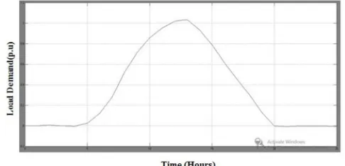
Figure 4: Generation Profiles Wind
[image:6.612.183.428.287.699.2]The average simulation time to perform the CCM has been estimated around 21 s by using a work station with an Intel Xeon E3-1230 V2 (3.30 GHz, 64 bit) processor, 16 GB of RAM and MATLAB™ R2013a. In any case, it is worth to note that the simulation times for all steps have been less than a minute, which are compatibles with the considered control step time of 10 minutes. However, the convergence times depend on the case study taken into account.
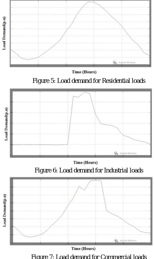
Figure 5: Load demand for Residential loads
Figure 6: Load demand for Industrial loads
Figure 7: Load demand for Commercial loads
Technology (IJRASET)
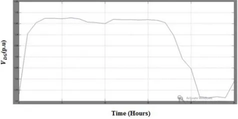
the three described control methods it is possible to achieve a correct voltage regulation.Figure 8: DGs bus voltages without control action for Bus 31
[image:7.612.187.426.280.399.2]The controller has been implemented in MATLAB™ setting the maximum number of iterations to 1000, considering a tolerance of 1e-3 for the step size, 1e-6 for the objective function and 1e-20 for the a geniture of any
Figure 9: DGs bus voltages without control action for Bus 44
Figure 10: DGs bus voltages without control action for Bus 46
[image:7.612.188.425.439.554.2] [image:7.612.186.426.585.703.2]Technology (IJRASET)
Figure 12: DGs bus voltages without control action for Bus 53
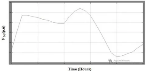
[image:8.612.185.425.319.430.2]constraint function. It is possible to seethe voltage profiles when no control actions have been applied. The dashed lines specify the band of the Control Range, where the greater one also indicates the maximum limit allowable for the voltage (1.05 p.u.). Indeed, as illustrated in Fig. 15for the bus 54, the voltage rise, due to the DG connected at the bus, is correctly regulated within the standard limits. In detail, the decentralised control methodcompared with the APCM allows reducing active power curtailments absorbing reactive power up to the limits imposed by the capability curves. As matter of fact, the simulation results highlighted an increment of 81.5% in the active power production.
Figure 13: DGs bus voltages without control action for Bus 54
However, as depicted in Fig. 8, the CCM allows injecting all the available active power increasing the active power production of 18.5% compared to the DCM. has been obtained increasing the reactive power absorption at the bus 46, which has not already reached the capability curves limits.
[image:8.612.192.423.510.615.2]Technology (IJRASET)
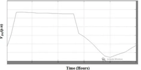
[image:9.612.187.425.232.352.2]Figure 15: DGs bus voltages with control action for Bus 44
Figure 16: DGs bus voltages with control action for Bus 46
Figure 17: DGs bus voltages with control action for Bus 47
[image:9.612.186.425.395.516.2] [image:9.612.186.424.559.678.2]Technology (IJRASET)
Figure 19: DGs bus voltages with control action for Bus 54
Fuzzy logic allows to lower complexity by allowing the use of imperfect information in sensible way. It can be implemented in hardware, software, or a combination of both. In other words, fuzzy logic approach to problems’ control mimics how a person would make decisions, only much faster.
The fuzzy logic analysis and control methods can be described as:
Receiving one or large number of measurements or other assessment of conditions existing in some system that will be analyzed or controlled.
Processing all received inputs according to human based, fuzzy ”if-then” rules, which can be expressed in simple language words, and combined with traditional non-fuzzy processing.
Averaging and weighting the results from all the individual rules into one single output decision or signal which decides what to do or tells a controlled system what to do. The result output signal is a precise defuzzified value.
Finally, a further check has been carried out on the capability curves. Indeed, Figures shows the set points elaborated by the IPPCC solving the constrained optimization problem. Also in this case the control works properly, in fact, all the set points are within the standard imposed by national code (dashed lines) and physical limits (continuous lines).
V. CONCLUSION
This project has introduced an optimization system connected to a SAB-DC for RES DGs, capable to maintain voltage levels inside administrative points of confinement while delivering the greatest accessible dynamic power. It stays away from the DG separation because of infringement of voltage limits at the connection bus and allows the DGs to offer auxiliary administrations to the DN. A bound together way to deal with the controller modeling on account of RES DGs associated with the DN by method for electronic converters and the greater part of the arrangements exhibited by the Pareto fronts is substantial limits for the streamlining issue. The decision of one of them speaks to the ideal tradeoff between active losses and receptive force minimization. The OSAB-DC is appropriate for huge DG entrance cases because of its "neighborhood" nature that decreases the many-sided quality of the control system contrasted and a totally brought together approach. It is described by a bound together and measured setup, and its effortlessness and adequacy would permit its reasonable execution. Actually, its augmentation because of new DGs associations requires, for instance, that the DSO includes the capacity details to the limitations segment and two variables for each every DG to the chromosome that speaks to the ideal arrangement to discover. By run the MOGA on the DN model it would be conceivable to assess the ideal edges. At that point, the online application of the OSAB-DC would be executed by detecting voltage levels at the DG association bus.
REFERENCES
[1] P. S. Georgilakis and N. D. Hatziargyriou, “Optimal distributed generation placement in power distribution networks: Models, methods, and future research,” IEEE Trans. Power Syst., vol. 28, no. 3, pp. 3420–3428, Aug. 2013.
[2] C.-H. Lo and N. Ansari, “Decentralized controls and communications for autonomous distribution networks in smart grid,” IEEE Trans. Smart Grid, vol. 4, no. 1, pp. 66–77, Mar. 2013.
[3] Vito Calderaro, GaspareConio, Vincenzo Galdi, Giovanni Massa, Antonio Piccolo “Optimal Decentralized Voltage Control for Distribution Systems With Inverter-Based Distributed Generators” IEEE TRANSACTIONS ON POWER SYSTEMS, VOL. 29, NO. 1, JANUARY 2014.pp 230-241.
[4] A. G. Madureira and J. A. Pecas Lopes, “Coordinated voltage support in distribution networks with distributed generation and microgrids,” IET Renew. Power Gener., vol. 3, no. 4, pp. 439–454, 2009.
Technology (IJRASET)
pp. 1063–1073, Jun. 2011.
[6] H.-G. Yeh, D. F. Gayme, and S. H. Low, “Adaptive VAR control for distribution circuits with photo voltaic generators,”IEEETrans.Power Syst., vol. 27, no. 3, pp. 1656–1663, Aug. 2012.
[7] V. Calderaro, V. Galdi, G. Massa, and A. Piccolo, “Distributed generation management: An optimal sensitivity approach for decentralized power control,” in Proc. 3rd Conf. Exhib. Innovative Smart Grid Technol., 2012, pp. 1–8.
[8] V. Calderaro, G. Conio, V. Galdi, G. Massa, and A. Piccolo, “Optimal decentralized voltage control for distribution systems with inverter - based distributed generators,” IEEE Trans. Power Syst., vol. 29, no. 1, pp. 230–241, Jan. 2014.
[9] O.A. Vokas, A.V. Machias, and J.L. Souflis, "Computer modeling and parameters estimation for solar cells", in 1991 Proc. Mediterranean Electro-technical Conf., vol.1, pp. 206 -209, May 1991
[10] Matlab/Simulink User’s Guide, TheMathworksInc, 2010.
[11] S. Conti and A. M. Greco, “Innovative voltage regulation method fordistribution networks with distributed generation,” in Proc. Int Conf. Electricity Distrib., 2007, pp. 1–4.
[12] V. Calderaro, G. Conio, V. Galdi, and A. Piccolo, “Reactive power control for improving voltage profiles: A comparison between two decentralized approaches,” Electr. Power Syst. Res., vol. 83, no. 1, pp. 247–254, 2012.
[13] K. Tanaka,M. Oshiro, S. Toma, A. Yona, T. Senjyu, T. Funabashi, and C. H. Kim, “Decentralised control of voltage in distribution systems by distributed generators,” IET Gener. Transm.Distrib., vol. 4, no. 11,pp. 1251–1260, 2010.
U.Gajapathi was born in Tada, Andhra Pradesh, India. He received the B.Tech degree in Electrical and Electronics Engineering from JNTU, Anantapur in 2014 and pursuing M.Tech degree in Electrical Power Systems (EPS) from JTNU,Anantapur AndhraPradesh, India. His areas of interests are Control Systems, Power Electronics and Drives and smart-griddevelopment issues, including integration of distributedgeneration systems on electrical distributionnetworks.