International Journal of Emerging Technology and Advanced Engineering
Website: www.ijetae.com (ISSN 2250-2459, ISO 9001:2008 Certified Journal, Volume 6, Issue 5, May 2016)
64
Protection of Induction Motor using Microcontroller
Shweta hugar
1, Basavaraj Amarapur
21
M.tech Student P.D.A college of Engineering Kalaburgi, India
2Professor, Electrical and Electronics Department, P.D.A College of Engineering, Kalaburgi, India
Abstract— Three-phase induction motors are industry’s workhorses and widely used as electromechanical energy conversion devices. Although induction machines are considered relatively reliable and robust due to their simple design and well-developed manufacturing technologies, failures do occur and may severely disrupt industrial processes and even lead to disastrous accidents. To prevent these failure happen, many techniques have been developed for early condition monitoring. The computer based protection methods are costlier and the electrical parameters cannot be visualized by Programmable Logic Controller (PLC) based method. The old classical methods are complex. Hence to protect an Induction motor easily, a microcontroller based fault detection and protection of Induction motor is proposed. This paper tends to develop for protection of three phase induction motor from over voltage and under voltage, over current, over speed, temperature, Line frequency and phase failure with their sensing circuits. The proposed system is tested with the setting of various preset values of parameters. From the results, it is observed that the results are satisfactory, reliable, gives quick response, cost effective and highly versatile.
Keywords— Fault, Microcontroller, Protection, Sensing Circuit and Three Phase Induction Motor.
I. INTRODUCTION
A large number of motors are being used for general purpose in our surrounding from house- hold equipment to machine tools in industrial facilities. Among all these motors Induction Motors are the most widely used motor for appliances, induction control, and automation; hence they are robust, reliable and durable. Although Induction Motors are reliable, they are subjected to some undesirable stresses, causing faults resulting in failure. Failure of such Induction motor may cause plant shutdown, personal injuries and waste of raw material. However, induction motor faults can be detected in an initial stage in order to prevent the complete failure of an induction motor and unexpected production costs. The main reason for the motor faults is mechanical and electrical stresses. Mechanical stresses are caused by overloads and abrupt load changes, which may cause bearing faults and rotor bar breakage. The electrical stresses may produce stator winding short circuits and result in a complete motor failure.
The electrically related faults such as voltage, current, under-voltage, under-current, overload, and over-temperature. Various protection methods are available in literature which uses components such as timer, contactors, voltage and current relays are used. The protection using solid state relay has been discussed [2] by designing sensing and control unit for the agriculture purpose using motor current signature analysis [MCSA] with wavelet transformer methods [3]. Artificial intelligent fault monitoring approach [4] Fourier spectral analysis using FFT and MATLAB programming for fault frequency methods [6] and Zig Bee based [7] methods are proposed.
The above said methods are simulation based methods. Recently the PLC based protection systems including all variable parameters of three phase induction motor have been proposed [5]. This method is based on computer and programmable integrated circuit (PIC). This eliminates most of the mechanical components. But they are highly complex system and costlier. In order to overcome these problems, the microcontroller based fault detection and protection of induction motor is proposed. In this proposed system, the induction motor is monitored by using microcontroller which plays a major role. The presented methods monitor the operating induction motor continuously with the minimum interaction of human body. Microcontroller based protection is having advantages over computer and classical based protection. The advantages of the proposed system are low cost, simple and higher accuracy. The protection of induction motor by different faults such as over/under voltage, over current, over speed, phase failure, frequency and over temperature are considered in this proposed work.
II. BLOCK DIAGRAM OF PROPOSED SYSTEM
International Journal of Emerging Technology and Advanced Engineering
Website: www.ijetae.com (ISSN 2250-2459, ISO 9001:2008 Certified Journal, Volume 6, Issue 5, May 2016)
[image:2.612.36.291.129.428.2]65 Fig. 1. Block diagram of proposed System
A. Over /under voltage sensing circuit
The over voltage occurs when any one of the line voltage increases above the rated voltage and it leads to harmful effect on machine insulation. In order to overcome this problem, over voltage sensing unit is designed. The designed unit consists of three potential transformers to step down the line voltage to 12V. This step down voltage is rectified and filtered to get dc voltage proportional to the line voltage. This dc voltage is compared with reference voltage which has set by the pre set value. This comparator is formed using quad op-amp IC LM 324 and the output of the comparator is fed to priority encoder IC 74148.
Under voltage occurs, when reduced supply voltage with the rated mechanical load on the he machine produces and intern increase in stator and rotor losses. In order to overcome this problem, under motor. Due to this increased current, excess heating of t voltage sensing circuit is designed .The under voltage sensing circuit uses the dc output from the over voltage sensing circuit and compared with the reference voltage in the comparator wired using op-amp LM324. The output is then fed to another input of the priority encoder IC 74148.
B. Overload sensing circuit
When there is increase in mechanical load on the motor beyond the rated value then the overload situation occurs. Due to this increase in current beyond the rated current then motor gets heated up and causes harm to the motor. In order to overcome this situation, the overload sensing circuit is designed.
The designed circuit is used to monitor the load current using Hall Sensor module AC5712, which senses the current up to 20Amp. This module gives dc output proportional to the input ac line current. This dc voltage is further amplified and compared using comparator with reference voltage. The output by the comparator is fed to one of the input of priority encoder IC 74148.
B. Temperature sensing circuit
When the motor runs for longer period under loaded condition of the motor and it gets heated up which reduces the efficiency of the motor. In order to sense over temperature, Semiconductor IC LM35 is used. This sensor provides 10mv/ºc output voltage proportional to the increased temperature of the motor. This output is amplified by using op-amp LM 324 and the output is compared with the reference voltage in the comparator formed by op-amp LM324. The output is fed to the priority encoder IC 74148.
D. Phase failure sensing circuit
In case of 3-phase Induction motor, three phase supply is needed. If any one of the phase fault occurs then remaining two phases are overloaded and gets heated up. In order to overcome this problem the phase failure sensing circuit is designed.
This unit uses the three low ac voltages from three step down transformers for sensing the three phase voltage. These ac voltages are fed to Schmitt trigger formed by IC555. The outputs of three Schmitt triggers are fed to AND gates formed by IC CD4081. The digital outputs are then fed to priority encoder IC 74148.
E. Line Frequency sensing circuit
Frequency is directly proportional to speed of the motor. If any change in frequency then the speed also varies and that will effects on the bearing, shaft connected to load of the motor due this winding may burned out. In order to avoid this, frequency sensor circuit is designed.
International Journal of Emerging Technology and Advanced Engineering
Website: www.ijetae.com (ISSN 2250-2459, ISO 9001:2008 Certified Journal, Volume 6, Issue 5, May 2016)
66 This frequency to voltage converter gives dc voltage proportional to the input line frequency. This dc voltage is then fed to comparator reference voltage the output of the comparator is fed to the input of priority encoder.
F. Speed sensing circuit
Increase in speed leads to increase in operating temperature and decreases the functional horse power, which leads to reduce the life of motor. In order to sense the speed, the speed sensing circuit has been designed. The circuit consists of proximity sensor to send the speed of the motor. The output of the sensor is proportional to the speed of the motor and it is dependent on voltage. which is proportional to the dc voltage. This dc voltage is compared with reference voltage in the comparator formed by LM 324. Then output is fed to the priority encoder IC 74148.
G. Implementation
The designed system implementation has been carried out using two different implementations, namely hardware and software implementation.
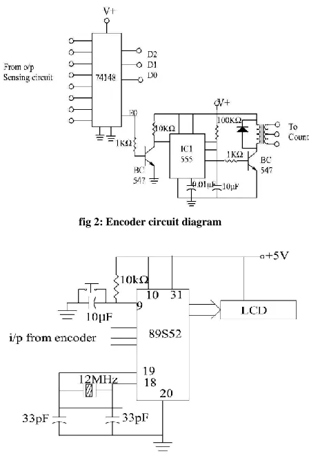
In hardware implementation six sensing circuits were designed and those six sensor circuit outputs are connected to the 8:3 priority encoder circuit using IC 74148 as shown in figure 2. This encoder generates three bit BCD output and one bit enable output. The BCD output which is generated by the priority encoder is completely based on the input provided by the designed sensing circuits. The BCD outputs are connected to the 89C52 microcontroller. The main function of microcontroller is to display the fault conditions on LCD display with audio system with buzzer as shown in the figure3.
[image:3.612.335.559.136.466.2]To minimize the starting surge current drawn by the motor, a delay of 30 seconds is generated using enable output of the priority encoder. The enable output of encoder is used to prevent tripping of the circuit at the starting and it generates the control signal to drive the relay driver. Which in turn isolate relay from switching of the motor during the faulty conditions. The faulty conditions considered are Over/Under voltage, over current, over temperature, phase failure, over speed and frequency.
fig 2: Encoder circuit diagram
Fig 3. Microcontroller circuit diagram
In software implementation has been carried out using the algorithm has been carried algorithm for the implementation of program is given below. If any fault occurs then the microcontroller sense the corresponding fault and displays the result on LCD display with audio signals.
Algorithm
Step1: Start
International Journal of Emerging Technology and Advanced Engineering
Website: www.ijetae.com (ISSN 2250-2459, ISO 9001:2008 Certified Journal, Volume 6, Issue 5, May 2016)
67 Step3: The encoder produces 3 bit BCD output based on the input given.
Step4: The BCD outputs are given to the microcontroller.
Step5: The microcontroller executes the related program based on the 3 bit output and Display the result on LCD.
Step6: If the output is 000 it Display it display ―No Fault‖. 6.1: If the output is 001 it Display it display ―Over Voltage‖. 6.2: If the output is 010 it Display it display ―Under Voltage‖. 6.3: If the output is 011 it Display it display ―over current‖.
6.4: If the output is 100 it Display it display ―over Temperature‖.
6.5: If the output is 101 it Display it display ―Over Speed‖. 6.6: If the output is 110 it Display it display ―Line Frequency‖. 6.7: If the output is 111 it Display it display ―Phase Failure‖. Step7: End
III. RESULTS
In the proposed system variable resistance (preset) is used for adjusting reference voltages for different parameters such as under/over voltage, over current, over temperature, over speed, frequency and phase failure. The values are set for the max. 430v, current 7.1amp, temperature50ºC.observations are listed in table , shown below.
If the value of any parameter goes beyond the reference value than the relay unit releases the contact of the motor from the circuit. Hence the motor automatically turned–off. This is how the Induction Motor can be protected easily from the faults using this microcontroller based protection system. This system can be tested with various different rated Induction Motors.As per the designed value, the system withstand current up to 20amp,voltage up to 450V,temperature up to 120 ºC and speed of 6000rpm
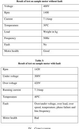
[image:4.612.315.573.144.564.2]Table 1: Test motor specification
Table 2:
Result of test on sample motor without fault
Table 3:
Result of test on sample motor with fault
IV. CONCLUSION
Protection of three phase induction motor from over/ under voltage, over current, over speed, temperature, frequency and phase failure provide the smooth running of motor which also improves its lifetime and efficiency. To make induction motor run efficiently and to protect it from various faults, six different sensing circuits have been designed along with audio system. These sensing circuit sense the faults occur in an induction Motor. These faults are monitored by the protection system and if any fault occurs the motor automatically turned off.
Rated voltage 415V
Rated current 7.5Amp
Frequency 50Hz
Hp 5HP
Phase 3 Phase
Rpm 1420
Winding insulation Class b
Bearing type Roller thrust bearing
Voltage 400V
Rpm 1400
Current 7.1Amp
Temperature 30ºC
Load Weight in kg
Frequency 50Hz
Fault No
Motor health Good
Rpm 1420
Under voltage 300V
Over voltage 420V
Running current 7.3Amp
Temperature 40ºC
Fault Over/under voltage, over load, over speed, temperature, phase failure and line frequency
[image:4.612.42.295.524.695.2]International Journal of Emerging Technology and Advanced Engineering
Website: www.ijetae.com (ISSN 2250-2459, ISO 9001:2008 Certified Journal, Volume 6, Issue 5, May 2016)
68 Hence protecting the Induction Motor by various faults. This prototype model of microcontroller based protection system is very simple in design, reliable, highly versatile, and cost effective and gives quick response. The system can work with any three phase induction motor
REFERENCES
[1] Malik Abadulrazzaq Alsaedi. ―Fault Diagnosis of Three-Phase Induction Motor: A Review‖. Optics. Special Issue: Applied Optics and Signal Processing. Vol. 4, No. 1-1, 2015, pp. 1-8. doi: 10.11648/j.optics.s.2015 040101.11
[2] S.Assly Steffy, B.mangaiyarkarasi, S.Sherin Jasper, K.Priyanka, K.Soorya ―An Improvement in Winding Protection of Three Phase Induction Machine Using Solid State Relays‖. International Journal of Advanced Research in Computer and Communication Engineering Vol. 3, Issue 2, February 2014
[3] P.E. Elavenil , Dr. R. Kalaivani ―Speed Monitoring And Protection Of Motor Using Zigbee Communication‖ .International Journal of Scientific Research Engineering & Technology (IJSRET) Volume 2 Issue 11, February 2014.
[4] Ms. Patil Smita Jaywant, Mr. Patil Sachin sambhaji and Ms.Patil Pragati Deepak ―Fault Detection and Correction of 3-phase Induction Motor‖. International Journal of Advanced Research in Electronics and Communication Engineering (IJARECE) Volume 3, Issue 8, August 2014.
[5] Sumit Narwade, Prasad Kulkarni and C.Y.Patil ―Fault Detection of Induction Motor UsingCurrent and Vibration Monitoring‖. International Journal of Advanced Computer Volume-3 Number-4 Issue-13 December-2013.
[6] K.K.Pandey, P.H.Zope, S.R.Suralkar, ―Review on Fault Diagnosis in Three-Phase Induction Motor.‖ International Journal of Computer Applications (IJCA) 2012.
[7] Oscar Poncelas, Javier A. Rosero, Jordi Cusidó, Member, IEEE, ―Motor Fault Detection Using a Rogowski Sensor Without an Integrator‖. IEEE Transactions On Industrial Electronics, Vol. 56, No. 10, October 2009
[8] Ramazan Bayindir, Ibrahim Sefa, Ilhami Colak and Askin Bektas ―Fault Detection and Protection of Induction Motors Using Sensors‖. IEEE Transactions on Energy Conversion,Vol. 23, No. 3, September 2008
[9] Neelam Mehala, Ratna Dahiya ―Motor Current Signature Analysis and its Applications In Induction Motor Fault Diagnosis‖ INTERNATIONAL JOURNAL OF SYSTEMS APPLICATIONS, ENGINEERING & DEVELOPMENT Volume 2, Issue 1, 2007 [10] M.A.S.K. Khan, Tawifik S. Radwan, M.Azizur Rahman ―Real Time
Implementation of Wavelet Packet Based Diagnosis and Protection of Three Phase Induction Motor‖ IEEE Transaction on Energy Conversion.Vol.22.no.3 September 2007
[11] Erdal Kilic,Okan Ozgonenel ―Fault Identification In Induction Motors With RBF Neural Network Based On Dynamical PCA‖. 2007 IEEE