International Journal of Emerging Technology and Advanced Engineering
Website: www.ijetae.com (ISSN 2250-2459, ISO 9001:2008 Certified Journal, Volume 7, Issue 6, June 2017)
A Novel Method of AC Power Generation from Solar Cells:
Prototype Design
Akhilesh A. Nimje
1, Yash Joshi
2, Sarthak Goyal
31Associate Professor, Electrical Engineering, Nirma University, Ahmedabad 382 481, India 2 ,3
Student, Final Year B. Tech., Electrical Engineering, Nirma University, Ahmedabad 382 481, India
Abstract-- Fossil fuels have been the source of energy for a long time as it serves major energy demand. Electrical energy is used by residential consumers, industries and other sectors because of its reliability. The electrical energy extracted from fossil fuels has deleterious effect on environment. Moreover the fossil fuels are on the verge of extinction and hence there is a need to explore alternate energy sources which are renewable in nature. Sunlight is the abundant source of energy and hence its utilization has been proven beneficial and will help towards reserving fossil fuels. Solar cells are one of the means to harvest solar energy. It converts solar energy into electrical energy (DC) which in turn is converted into AC using power electronic devices. Conventional method uses inverters to obtain AC from DC. But the inverters, like any other electronic equipment, dissipate heat and loose a significant part of the energy collected by solar cells. In this novel approach, a method has been introduced which obviate the need of using converters and inverters for conversion of DC to AC. In the proposed method, a mechanical system periodically occludes the solar cells to simulate an AC wave. The novel approach may prove to be energy efficient and economically viable than conventional inverters for small scale power generation.
Keywords-– Alternating current, solar cells, panel
connection, regulator, FFT analysis.
I. INTRODUCTION
The rapid industrialization and per capita consumption of electricity is the index for assessing the growth of a nation. In India, there has been a considerable growth in power sector in terms of installed capacity from 1465 MW (1947) to 3,30,260 MW (31 May 2017). The target of adding 175 GW by the year 2022 is plagued by the limited availability of fossil fuel resources. Hence the paradigm has shifted from usage of fossil fuels to the renewable energy sources. There is an urgent need to explore newer methods of power generation such as solar, wind, hybrid solar-wind, micro-hydro and many more. The Jawaharlal Nehru National Solar Mission aims to achieve 100 GW from solar energy. A significant research has been done to reduce the cost of solar energy during last four decades. Therefore, the energy from sun is gaining momentum from all corners of the globe. The improved quality of life demands greater consumption of electricity.
[image:1.612.328.562.375.441.2]The per capita consumption in India is 1100 kWh which is far less compared to those of the developed countries having it from 8000 to 16000 kWh. India has a great potential to explore solar energy as it has more than 300 bright sunny days in a year. The average solar radiation in India is 200 MW/km2. Thus, there is a large scope of utilizing solar energy for domestic appliances such as solar cooker, heating to a large multi-megawatt solar thermal power plants. The solar cells convert solar energy to electrical energy. The energy so generated is DC that needs to be converted into AC as majority of appliances are powered by AC source.
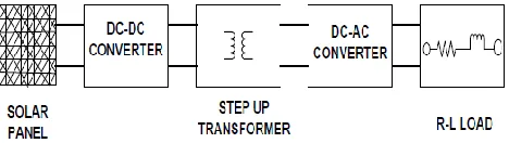
Fig. 1 Conventional Topology of Converting Solar Power Output to AC
International Journal of Emerging Technology and Advanced Engineering
Website: www.ijetae.com (ISSN 2250-2459, ISO 9001:2008 Certified Journal, Volume 7, Issue 6, June 2017)
An LC filter is therefore connected at the output of inverter parallel to the load for removing undesirable harmonics thus producing a pure sinusoidal wave. The proposed methodology presented in this paper avoids the use of DC-DC converter, transformer, PWM and inverters.
[image:2.612.58.299.202.346.2]II. NOVEL METHOD OF AC POWER GENERATION
Fig. 2 Proposed Method of Converting Solar Output to AC
The energy collected by the solar cell is directly proportional to the area of the panel exposed to the sun. By periodically occluding parts of the cell, an AC wave can be generated. If the energy required by a motor is less than the energy loss incurred by an inverter, then the mechanical solution may be more optimal than using an inverter topology. It is also important to note that commercial electric motors are cheaper than inverters. Figure 2 describes the output waveform from solar panel at different time T. When the solar panel is completely occluded by a disc at t=0, the output voltage is zero. As the disc moves, the voltage starts rising, thus at t=1/4, voltage becomes half of the peak voltage. When the disc is completely removed, the output voltage becomes maximum that is at t=1/2. Again when the disc starts covering the solar cells, the output voltage drops. This cyclic process continues and an alternating waveform is obtained. The proposed idea eliminates the usage of inverter. The mechanical arrangement so designed serves the purpose same as the inverter/ converter and transformers. The frequency of the output and its wave shape is the function of speed of the circular disc and the number of holes on it. Since the intensity of sunlight falling on the cells periodically changes, it is possible to get a periodic wave at the output. According to the concept, the motor runs at a constant speed with the disc mounted on it and the disc has five holes which makes the solar radiation to fall on the solar cells of first series and other solar cells of the second series remains occluded.
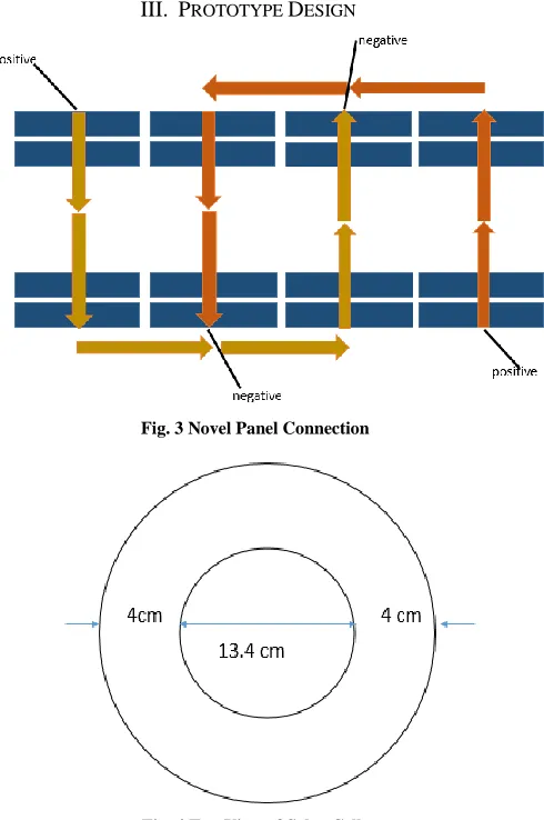
After 10 m-sec, the condition gets reversed, the second series is subjected to sunlight and first series is occluded. This cycle keeps on repeating thereby providing a ripple DC output which gradually rises and reaches to the maximum value and then gradually decreases to zero. The outputs are having a time difference of 10 m-sec. When the first series is subjected to sunlight, it gives output for 10 m-sec and then drop to zero and the next series is subjected to sunlight and gives output for next 10 m-sec and then drop to zero. This process continues periodically and gives 2 different outputs with time difference of 10 msec. The rpm of motor is set to a value such that each series is subjected to sunlight for 10 m-sec. The positive of both the odd and even solar cell series are connected together and both the negative of the odd and even solar cell series will serve as output terminals as shown in Fig. 3.
III. PROTOTYPE DESIGN
[image:2.612.329.574.331.700.2]Fig. 3 Novel Panel Connection
International Journal of Emerging Technology and Advanced Engineering
[image:3.612.67.298.119.421.2]Website: www.ijetae.com (ISSN 2250-2459, ISO 9001:2008 Certified Journal, Volume 7, Issue 6, June 2017)
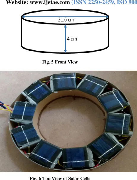
Fig. 5 Front View
Fig. 6 Top View of Solar Cells
[image:3.612.328.575.120.249.2]The arrangement of the prototype design consists of 10 cells with numbering from 1 to 10. The even numbered cells are connected in series and odd numbered cells form another series. Both these series arrays are connected in parallel such that positive of both the series connected cell are connected together and the other terminals together serve as negative. Series connection is done for increasing the voltage. Several series are connected in parallel to increase the current. Both series together produces 10 volt, 100 mA. DC motor is supplied by a separate power source comprising of 4 number of 5 volt solar cells. The solar output is the function of intensity of sunlight. Hence, a regulating IC LM7812 is required as shown in Fig. 4. A separate circuit is provided for voltage regulation and speed control of motor in which solar cell output is fed through LM7812 voltage regulation IC. A potentiometer is required for adjusting the speed.
Fig. 7 Voltage regulator circuit
IV. RESULTS
[image:3.612.325.571.356.550.2]Individual series array has an output waveform which is DC ripple in nature with some offset and both series output are 180 degree phase shifted from each other. Both the series are individually shown in Fig. 8 with blue and red waveform.
International Journal of Emerging Technology and Advanced Engineering
[image:4.612.50.287.133.321.2]Website: www.ijetae.com (ISSN 2250-2459, ISO 9001:2008 Certified Journal, Volume 7, Issue 6, June 2017)
Fig. 9 Output waveform of two array
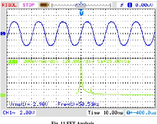
As the sunlight falls on one array at a time, the other array is completely occluded. Hence, the output is generated by only one array. The other parallel array generates no output. During the next half, the reverse condition is seen. Thus, there is 180 degree phase shift between the outputs of these two arrays. Both these waveforms with 180 degree phase shift with DC offset has been shown in Fig. 9. Output sine waveform has peak to peak voltage of 8V and frequency of 50.5 HZ and can be varied as per requirement with variation in speed of motor by varying the input voltage. When the FFT or total harmonic distortion analysis was performed, it has been found that third harmonic is present with a very small voltage and no other harmonic is present.
Fig. 10 Output of Solar Cells
[image:4.612.323.584.197.403.2]Sine wave has been obtained from the prototype output and the frequency is function of speed of DC motor. Y-axis represents the voltage axis and X-axis represents the time axis. Voltage scale is set to 2 volt per division and time scale is set to 10 m-sec per division.
Fig. 11 FFT Analysis
V. DISCUSSION AND CONCLUSION
The output waveform is sinusoidal in nature with least harmonic content as compared to the traditional method with power electronic components. The material for rotating disc needs to be light as well as stiff. The frequency of output voltage at 50 Hz is the function of the number of holes and the motor speed. The prototype promises to be cost effective for small scale solar power generation. The efficiency of prototype may be improved by putting it in vacuum. Research for its improved design and efficiency for its implementation on mainstream is on the charts of future work. The proposed idea may be put in use where power quality is not the major concern and can be used in remote areas or island where electricity is not easily available.
Acknowledgement
[image:4.612.48.287.506.694.2]International Journal of Emerging Technology and Advanced Engineering
Website: www.ijetae.com (ISSN 2250-2459, ISO 9001:2008 Certified Journal, Volume 7, Issue 6, June 2017)
REFERENCES
[1] S. B. Kjaer, et al, “A Review of Single Phase Grid Connected Inverters for Photovoltaic Modules”, IEEE Transactions on Industry Applications, vol. 41, pp 1292-1306, 2005.
[2] M. Calais, et al, “Inverters for Single Phase Grid Connected Photovoltaic System - An Overview”, Power Electronics Specialist Conference, 2002, PESC 02, 2002, IEEE 33rd Annual, pp 1995-2000.
[3] Atul S. Lilhare1, Vaibhav R. Doifode2, Prasad B. Joshi3, Pranay S.
Shete4, “Off-Grid Single Phase Micro-Inverter System”,