International Journal of Emerging Technology and Advanced Engineering
Website: www.ijetae.com (ISSN 2250-2459,ISO 9001:2008 Certified Journal, Volume 4, Issue 7, July 2014)
169
PRS Based Microstrip Antenna for Beam Steering
Applications
A. Swetha
1, Dr. P. Nageswara Rao
2, B. Naga Prasanna
31
M.Tech student of G. Pullaiah College of Engineering and Technology, kurnool-518002, Andhra Pradesh, India.
2Principal, 3Assistant Professor, Department of Electronics and Communication Engineering. G. Pullaiah College of
Engineering and Technology, kurnool-518002, Andhra Pradesh, India.
Abstract----This paper proposes a technique which improves Directivity and control of Beam-Steering by including metamaterial surfaces onto microstrip patch antenna superstrate used for wireless communication applications. Metamaterials are designed with Artificial Magnetic Conductor (AMC), inductive and capacitive planar structures. These structures allow obtaining Partially Reflective Surfaces (PRS).
The antenna used is a rectangular microstrip patch which operates nearly at a frequency of 11.92 GHz. The PRS reflector used for the design of the steerable directive beam antenna consists of a periodic array of copper strips. By using Metamaterial based microstrip patch antenna it is possible to improve the performance of antenna, in terms of Beam steering and directivity. These antennas are more useful in telecommunication systems requiring compact low profile and environment friendly directive antennas. This paper deals with design aspects of PRS based antenna and to study its properties. Based on the study, simulations are carried out on PRS based antenna and the same is fabricated for testing to analysis the results.
Keywords--- Metamaterial, Microstrip patch antenna, Artificial Magnetic Conductor (AMC), Partially Reflective Surfaces (PRS), IE3D software, Beam steering.
I. INTRODUCTION
There has been a lot of study was done on the improvement of the performances of micro strip patch antennas [1] - [2]. The solutions which have been planned in the past were to use an array of a number of antennas. In an array of a number of antennas technique that provides a difficulty which comes from the feeding of each antenna and also coupling between each element. So, this paper provides an exciting solution that is a micro strip patch antenna is going to make use of a PRS surface above the patch antenna.
A. PRS Surface
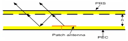
A cavity antenna is formed by a feeding source positioned between two reflecting surfaces. The cavity which is shown in Fig. 1 is made of a PEC surface acting as a normal ground plane for the feeding source and a metamaterial - based surface acting as a transmitting window known as PRS.
[image:1.595.323.539.293.363.2]To reduce the dielectric losses a patch antenna can use a PEC surface as the antennas ground plane and only one sub wavelength metamaterial - based surface known as the PRS surface.
Fig. 1: Resonant microstrip cavity antenna formed by a PEC and a PRS surfaces.
This paper is going to present the design and characteristics of an optimized resonant cavity antenna for a beam steering applications to operate near at 11.92 GHz. The cavity consists of a PEC surface and a new one-dimensional metamaterial surface made of metallic strips composing of a non uniform capacitive grid and a uniform inductive grid, acting as the PRS [3]. So that it can provide a low profile antenna in terms of low cost, less weight and for beam steering applications.
B. Microstrip Patch Antennas
A Microstrip patch antenna is a thin rectangle patch on one side of a dielectric substrate and the other side having a plane to the ground. The patch in the antenna is made of a conducting material Cu (Copper) or Au (Gold) and this can be in any shape, rectangular, circular, triangular, and elliptical or some other common shape.
C. Dimensions of the Rectangular Patch
International Journal of Emerging Technology and Advanced Engineering
Website: www.ijetae.com (ISSN 2250-2459,ISO 9001:2008 Certified Journal, Volume 4, Issue 7, July 2014)
170
II.PEC–PRSSURFACES
In this section, a paper is gong to discuss about the design of planar metamaterial – based PRS surface of a microstrip antenna to operate near at a frequency of 11.92 GHz.
From Fig. 1 a cavity is produced by a feeding an antenna which is placed between two reflectors isolated by a distance of h. Phase shifts are introduced by these two reflectors and also by the path length of the wave travelling inside the cavity. With the multiple reflections of the wave emitted by the antenna, so that the reflected waves are in phase after one cavity roundtrip. The resonance state is achieved and can be written as:
PRS r
(
+
4
2
h
N
(1)Where, ΦPRS is the reflection phase of the PRS reflector, Φr is the reflection phase of the PEC reflector near the antenna and N is an integer.
[image:2.595.325.552.336.422.2]By using only a single PRS reflector above the microstrip antenna provides the advantage of offering lower losses. A new PRS composed of simultaneously a capacitive and an inductive grid on the two faces of a dielectric substrate is designed in Fig. 2.
Fig. 2: Elementary cell of the composite metamaterial, showing the capacitive and inductive grids.
With reference to the metallic patches of the capacitive grid, a Period of a = 4.4 mm and a width of w1 = 7.8 mm are used. A line width w = 1.4 mm is considered for the mesh of the inductive grid.
A. Passive Steering Beam Cavity Antenna
A 1mm (λ/30) thick cavity is designed with side dimensions of 36 mm x 7.8 mm where the resonance frequency is achieved at around 11.92 GHz. At this resonance frequency the cavity is well matched. In this section, it reports the design of a beam steering antenna using a metamaterial – based PRS surface as a sub wavelength cavity as shown in Fig. 5. Generally, phased-arrayed antennas are used by implementing an electrical phase differences between the antenna elements so as to steer a beam into a desired direction [5]. Although this solution provides fast scan speed, but it requires many phase shifters connected to each antenna element, which is very expensive for communication systems.
The approach of this paper is completely based on a cavity made of a normal PEC ground plane and a new one-dimensional metamaterial with a locally phase variable acting as a Partially Reflective Surface cavity from a Fig. 1. So, first of all this paper will describe the study and design of this new phase - varying metamaterial based PRS surfaces and then its application for a cavity antenna.
B. Combination Of Unidimensional Metamaterial Based Prs Surface For Variable Phase
[image:2.595.52.276.431.528.2] [image:2.595.315.555.480.589.2]The PRS reflector used for the designing of the steerable directive beam antenna consists of a periodic array of copper strips automatically placed on each face of the 1.575 mm thickness of RT/duroid 5880 (εr = 2.2 and tan δ = 0.0009) material as a substrate as shown in Fig. 3.
Fig. 3: 3D view of a designed PRS based microstrip antenna for Beam Steering
The periodicity a and the width w of the strips is respectively 4.4 mm and 1.4 mm.
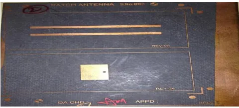
Fig. 4(a): Captured picture of front end of a PRS based microstrip antenna for beam steering
International Journal of Emerging Technology and Advanced Engineering
Website: www.ijetae.com (ISSN 2250-2459,ISO 9001:2008 Certified Journal, Volume 4, Issue 7, July 2014)
171
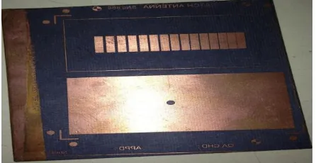
An increase in the value of g causes a decrease in the value of the capacitance created between two cells and lastly a shift of the resonance occurs towards higher frequencies. At a particular frequency the phase of the PRS increases with an increase in the gap spacing. This phase shift is very important because it will help radiated beam of a PRS based microstrip antenna into a desired direction.
Fig. 4(b): Captured picture of rear end of a PRS based microstrip antenna for beam steering
C. Beam Steering Cavity Antenna
[image:3.595.53.276.234.349.2]In order to make the antenna beam steerable, the PRS of the cavity must be designed in such a manner that a continuous phase variation is going to be occurred. The previous study on the variation of g leads us to a new design of the PRS (Fig. 5) with a continuous variation of the gap g. As illustrated by the cavity antenna system shown in Fig. 5, the proposed PRS is now divided into seven different regions, where each of them has definite gap spacing. The basic gap spacing g (g =400 μm) in the centre of the PRS is taken as a reference and a dual variation of ± n δg (with n = 0, 1, 2, 3) is placed on each side of the central region. The gap spacing is thus incremented frequently when moving from the left to the right along the PRS. If we consider each gap as a slot antenna, a resembling can then be made with an array of seven antennas with a regular phase difference.
Fig. 5: Graphical representation of the cavity composed of a PEC and a metamaterial-based phase-varying PRS.
Several prototypes of the sub wavelength cavity have been simulated, fabricated and measured.
The first one consists of the metamaterial based PRS surface with the same gap spacing g between the metallic strips of the capacitive grid (δg = 0). This prototype will guarantee no deflection of the beam since it exists no phase variation of the metamaterial based PRS surface. The second, third and fourth one are the prototypes which are going to make use of a spacing of δg = 25 µm, δg = 50 μm and δg = 100 μm along the positive x -direction. The cases where the variation of δg is negative (180° rotation of the PRS around the z-axis) have also been considered. The resonant frequency of a PRS based microstrip antenna which depends on the phase of the reflection coefficient of the PRS and also the height of the foam. The optimized cavity thickness h = 1 mm, a = 4.4 mm, w = 1.4 mm, g= 400 μm, δg = 0. The beam is normal to the plane of the antenna and shows no deflection, which confirms our calculation on the constant phase metamaterial based PRS surfaces.
However, in the case of a regular variation of 25 μm, a deflection of the antenna beam of about 5° can be observed either in the forward (clockwise) or backward (anti-clockwise) direction depending if δg is respectively negative or positive. Similar observations and a higher deflection of ±10° can be noted for δg = ± 50 μm.
III. RESULTS AND DISCUSSION
IE3D (Integral Equation Three-Dimensional electromagnetic simulator) software is used to model and simulate the PRS based microstrip antenna based on the method of moments. IE3D simulator analysizes 3D and multi layer structures of general shapes. It is used to calculate and plot return loss and VSWR Characteristics, as well as radiation pattern.
Fig. 6: IE3D Layout of a PRS based rectangular microstrip antenna
A. Return Loss Characteristics and Bandwidth
[image:3.595.53.274.587.696.2]International Journal of Emerging Technology and Advanced Engineering
Website: www.ijetae.com (ISSN 2250-2459,ISO 9001:2008 Certified Journal, Volume 4, Issue 7, July 2014)
[image:4.595.54.274.142.270.2]172
Fig. 6: Simulated Characteristics of Return loss
It can be observed that the return loss of the PRS based microstrip antenna operates at 11.55 GHz of frequency was -13.8 dB where, return loss was minimum. Comparing with the measured value using network analyzer E5071C we observe the return loss as -11.55dB at 11.92 GHz of frequency as shown below;
Fig. 7: Measured Characteristics of Return loss
As for the bandwidth of the antenna, it is defined as the frequency range over which return loss is less than or equal to –10dB. The bandwidth can be calculated using the following equation:
BW
(
x
100%
(2)Where,
f0 is the centre frequency or the frequency where return loss is minimum. f1 and f2 are the frequencies at which return loss equals to –10dB. Applying the above-mentioned equation, the calculated bandwidth of the PRS based microstrip antenna is approximately about 8%. From the above measured value the centre frequency f0 operates at 11.92 GHz having return loss characteristics as minimum and difference between f1 and f2 values are considered at which return loss is -10db by calculating
that values bandwidth is approximately is equal to 7.4%.
B. Voltage Standing-Wave Ratio
[image:4.595.328.549.220.356.2]As for the Voltage Standing-Wave Ratio (VSWR), it is defined as a measurement of the mismatch between the load and the transmission line. Therefore, the simulated VSWR characteristics for a PRS based microstrip antenna are as shown below:
Fig. 8: Simulated Characteristics of VSWR
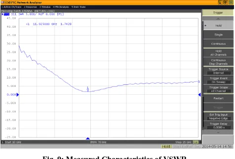
It can be observed that the simulated VSWR characteristics of a PRS based microstrip antenna which operates at a frequency in the range of 10.7 GHz to 14.5 GHz is 1.51, the VSWR of the antenna can be considered desirable as it is less than 2 and the measured value of VSWR characteristics is 1.74 at 11.92 GHz of frequency.
Fig. 9: Measured Characteristics of VSWR
[image:4.595.53.276.367.502.2] [image:4.595.315.553.446.607.2]International Journal of Emerging Technology and Advanced Engineering
Website: www.ijetae.com (ISSN 2250-2459,ISO 9001:2008 Certified Journal, Volume 4, Issue 7, July 2014)
[image:5.595.57.299.110.509.2]173
[image:5.595.50.290.334.517.2]Fig. 10: Different Radiation Pattern Simulated values of Beam Steering
Fig. 11: Measured Radiation Pattern of E-Plane for Beam steering of 5°
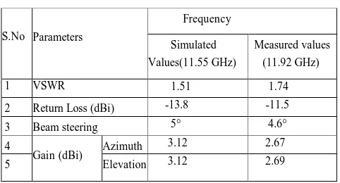
Table 1
comparison table between simulated and measured values
IV. CONCLUSION
This paper presents the design aspects of a PRS based microstrip antenna for beam steering applications. The radiation pattern test was carried out on a PRS based micro strip antenna and the same is fabricated for testing in order to analyze the results. Measured values are matching with the simulated values.
The PEC-PRS with a cavity thickness of 1mm (λ/30) is proposed for applications where the radiated beam can be steered into a desired direction. This phase-varying PRS is composed of inductive and capacitive strips and by varying the capacitance locally with a continuous variation of the gap between the capacitive strips, a variable phase is achieved. A fabricated of a PRS based microstrip cavity antenna of thickness λ/30 shows the possibility of obtaining a deflection of the beam of +5°.
REFERENCES
[1] D. R. Jackson and N. G. Alexópoulos, “Gain enhancement methods for printed circuit antennas,” IEEE Trans. Antennas Propag. AP-33(9), (1985).
[2] H. Nakano, M. Ikeda, K. Hitosugi, and J. Yamauchi, “A spiral antenna sandwiched by dielectric layers,” IEEE Trans. Antennas Propag. 52(6), (2004).
[3] R.Yahiaoui, S.N. Burokur and A. de Lustrac, “Enhanced directivity of an ultra-thin metamaterial-based cavity antenna fed by a multisource,” Electron. Lett., vol. 45, no. 16, pp. 814-816, July 2009.
[4] O. Luukkonen, C. Simovski, G. Granet and G. Goussetis, “Simple and accurate analytical model of planar grids and High Impedance Surfaces Comprising Metal Strips or Patches” IEEE Antennas and Propagation Letters, vol. 56, no. 6, pp. 1624-1632, June 2008.
[5] D.J. Kern, D.H. Werner, A. Monorchio and L. Lanuzza “The design synthesis of multiband artificial magnetic conductors using high impedance frequency selective surfaces” IEEE Antennas and Propagation Letters, vol. 53, no. 1, pp. 8-17 Jan 2005.
[6] C. A. Balanis, “Antenna Theory, Analysis and Design”, JOHN WILEY & SONS,INC, New York 1997.
Acknowledgment
We place on record and warmly acknowledge the continuous encouragement, invaluable supervision, timely suggestions and inspired guidance offered by Dr. P. Nageswara Rao, Principal, GPCET, JNTUA, Knl Dt.
We would like to give sincere thanks to Mrs Prameelamma, Technical Director, M/s ASTRA, unit-II, Hyderabad and Dr. B.V.Subba Rao, Manager of Range Instrumentation Systems, SDSC SHAR, Sriharikota who helped us in practical testing of PRS based microstrip patch antenna.
Finally we extend our gratitude to one and all who are directly or indirectly involved in the successful completion of this work.
S.No Parameters
Frequency
Simulated Values(11.55 GHz)
Measured values (11.92 GHz)
1 VSWR 1.51 1.74
2 Return Loss (dBi) -13.8 -11.5 3 Beam steering 5° 4.6° 4
Gain (dBi) Azimuth 3.12
2.67
5 Elevation 3.12 2.69
δg = 0µm
δg = 5 µm
[image:5.595.47.288.567.697.2]International Journal of Emerging Technology and Advanced Engineering
Website: www.ijetae.com (ISSN 2250-2459,ISO 9001:2008 Certified Journal, Volume 4, Issue 7, July 2014)
174
BIOGRAPHIES1
Mrs. A. SWETHA received the B.Tech degree in Electronics and Communication Engineering from Dr. K.V. Subba Reddy College of Engineering & Tech, JNTU Anantapur, A.P in 2012. Currently, she is pursuing her (M.Tech) in G. Pullaiah College of Engg & Tech Kurnool, JNTU Anantapur, A.P. Her current research interests includes study and designing properties of antennas and its applications.
2
Dr. P. Nageswara Rao received his
B.Tech degree from Nagarjuna University,
Guntur, India, in Electronics and
Communications Engineering and
Master’s degree from Coimbatore Institute of Technology, Coimbatore, India, in 1990 and 1995, respectively. He received his Doctoral degree from NIT Warangal. He worked as faculty in ECE department at NBKRIST, Nellore and Sree Vidyanikethan Engineering College, Tirupati for 10 years. Currently he is working as Principal at G. Pullaiah College of Engineering &Technology, Kurnool, A.P, India. His areas of interest are Numerical Electromagnetic and micro strip antennas.
3
Mrs. B. Naga Prasanna received her