Optimal Power Allocation Scheme for Downlink CoMP
Systems
Jun Li1, Han Hai1, Ying Guo2, Moon Ho Lee1
1Department of Electronic and Information Engineering, Chonbuk National University, Jeonju, Korea 2School of Information Science & Engineering Central South University, Changsha, China
Email: [email protected], [email protected], [email protected], [email protected]
Received 2013
ABSTRACT
Coordinated multi-point transmission and reception (CoMP) scheme enable LTE-Advanced systems to achieve their higher spectral efficiency. Allowing base stations to cooperate one another is one of the solutions to mitigate the inter- cell interference (ICI). In this paper, we propose an iterative power allocation scheme with MMSE procoding based on a modified water-filling for downlink CoMP systems, which achieves the optimal performance. The simulation results show that our proposed system can achieve its optimal rate according to its antenna configuration. Comparing them with a block diagonalization (BD) shows the advantages of MMSE precoding, in particular at a low SNR region.
Keywords: CoMP; Precoding; Power Allocation; Waterfilling
1. Introduction
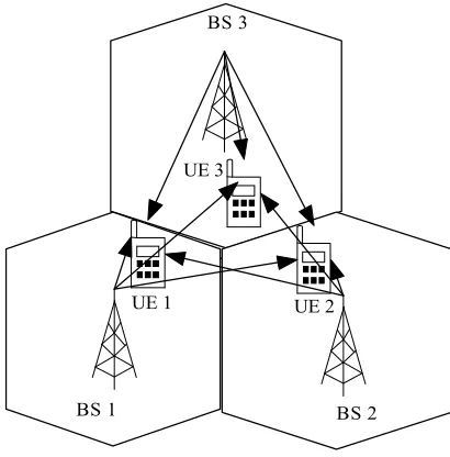
Coordinated multi-point transmission and reception (CoMP) scheme has been widely used for LTE-Advanced system to enhance cell average and cell edge throughput. Accord- ing to a coordinating fashion, CoMP scheme is classified into two strategies [1]: Joint processing (JP) and coordi- nated scheduing/beamforming (CS/CB). In the JP strategy as shown in Figure 1, each user equipment (UE) simul-
taneously receives data from multiple base stations (BSs) with joint multi-user precoding, which is required to share both user data and channel state information (CSI) between base stations (BSs) and user equipments (UEs). Stemming from that, this JP strategy could be used to contribute to not only improving the strength of the receive signal but also cancelling interference. However, it is re- quired to exchange the significant amount of data among links participating in its coordination. Besides, substan- tial overheads should be taken into account in the network.
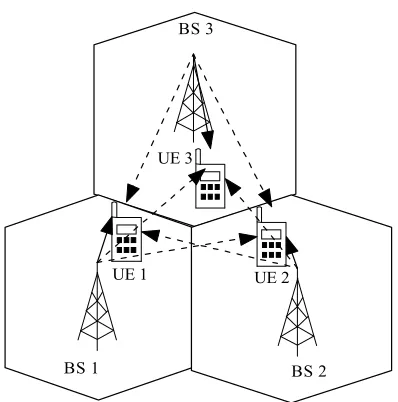
Compared with JP, CS/CB can avoid inter-cell inter- ference (ICI) by applying precoding to each BS on an in- dividual basis, which is required to share only CSI without holding user data in common. As depicted in Figure 2,
the solid lines denote the desired signals and the dashed lines denote the interference from other BSs locating in other cells. Since sharing CSI requires much lower ca- pacity than sharing data [2], CS/CB needs much lower backhaul capacity than JP. A lot of studies have been done on CS/CB [3-5]. However, an effective algorithm to eliminate the interference for downlink CoMP and network MIMO is still not sufficient. If the interference is known
at the transmitters, cooperative encoding using dirty paper coding (DPC) could mitigate the inter-cell interference (ICI) [6]. Apart from DPC, a zero-forcing (ZF) scheme based on block diagonalization (BD) is proposed in [7]. In [8], BD is applied to a multi-cell scenario with an ICI reduction scheme. However, as pointed out in [9], per- formance of BD is suboptimal at a low SNR. In this paper, we use the MMSE precoding to compensate the noise with the interference, with the goal of maximizing the weighted sum rate (WSR).
BS 1 BS 2
BS 3
UE 3
[image:1.595.319.524.510.718.2]UE 1 UE 2
BS 1 BS 2 BS 3
UE 3
[image:2.595.73.272.85.286.2]UE 1 UE 2
Figure 2. Coordinated scheding/beamforming (CS/CB
A solution to maximizing the WSR is proposed in [10] on
s organized as follows. In Section 2, we sh
2. System Model
e cluster which is comprised of
).
the condition that each UE is equipped with a single antenna and the precoding matrix is chosen in order to maximize the signal-noise-plus-interference ratios (SINR) for each user. Aside from this, a power allocation scheme is also proposed. In [11], non-iterative water-filling scheme is proposed to solve the problem occurring when applying BD.
This paper i
ow a proposed system model. In Section 3, we over-view conventional power allocation schemes and propose a modified optimal power selection scheme. In Section 4, we show that our proposed system outperforms conven-tional systems using computer simulation. In Section 5, we come to some conclusions.
Consider a cooperativ
both N BSs and N UEs on the condition that each BS is equipped with Nt antennas while each UE is equipped
with a single an na. In addition, each cell has both a single BS and UE, under the situation that each UE re-gards the nearest BS as its local BS.
Figure 3 illustrates our system mo
ten
del. Each BS is de-noted by each circle, which is represented by the (i), where 1 ≤ i ≤ N. Aside from this, N 1
, t
j i
h Î ´ indicates
the channel vector from a coordinate Ei, while
[image:2.595.309.539.86.259.2]N 1
[v , , v ]t
i i i
v = indicates a beamforming vector used to
rference between BSi and UEi. In addi-tion, the solid lines denote the desired signals while dashed lines denote the interference from the coordinated BSs.
Our p
d BSj to a U
mitigate the inte
roposed system is represented as follow. The re-ceived signal of UEi, yi is given by BSi with power Pi
(2) (1)
(N)
1
2
N
1 v
2 v
N
v
BSs UEs
1 x
2 x
N
x
1,1
h
1,2
h
1,N
h
2 ,1
h
2 ,2
h
2 ,N
h
,1
N
h
,2
N
h
,
N N
h
Figure 3. Downlink Multi-user beamforming of the CoMP.
nder CoMP transmission mode where
i
z (1)
Besides,
u i=1, , , N
, ,
1,
.
H H
i i i i i j i j j j j i y h vx h v x
= ¹
= +
å
+N
j
x
Sj
is the inter-cell interference signal trans-mitted by B . The desired signal xi of UEi is only
transmitted by BSi. zu denotes the noise at UEi, which
is a white Gaussian ra dom variable with zero mean and variance s2.
n
3. Power Allocation Scheme
The design of the precoding matrix V=
[
v1, vi, ,vN]
are chosen in
INR (2)
where SINR is the signal to noise-plus-interference ratio
and the optimization of the powers Pi order to maximize a WSR:
N
(
)
2 1
log 1 .
i i
i
R a S
=
=
å
+i
at each receive antenna. The value aiÎ[0,1] indicates
the priority of each user, in particular ual prior-ity,
case of eq
1
i N
a = , for all i.
In this section, the received SINR for UEi is
2
H
,
2 2
, 1,
,
i i i i
i N
H j i j j j j i
iSINR
P h v
s
= ¹
=
+
å
(3)
where
P h v
represents the norm, , 2
H i i i
h v
. is the desired
signal power of UEi, and , 2 1,
N H j i j j j j i
P
h v
= ¹
å
indicates the interference signal power from the other BSs. It should satisfy the condition of power constraint PmaxBS:2
max 1
.
N
i i BS
i
P v P
=
£
The beamforming matrix is chose MMSE criterion [12], which maximizes
receiver. Therefore, the beamforming matrix is repre-se
V n according to
the SINR at the
nted as 1 1 , H H N
V H HH I
-æ ö÷
ç ÷
= çç + ÷ (5)
r ÷
çè ø
where , is the sign
ratio (S a possibl
power is an N by N identity
where ).
For simplicity without loss of generality, we can ap-ate the equation (6) as
1
[ ]T
i M
H= h h h
NR), defined as a rat and noise power s2.
r io of N I al-to-noise e maximum matrix.
The general problem is to find the powers Pi to
sat-isfy
(
)
2
max log 1 ,
N
i SINRi
a
ì ü
ï ï
ï + ï
í
å
ý (6)1 i= ï ï ï ï î þ [0,1] i
a Î (
1 1
N i i=a =
å
proxim 2 2 log 1 H N i P h v a æ ö÷ ç ÷ ç ÷ ç ÷ çç + çå
, 2 1 , 1, .i i i i N
H i
j i j j j j i
P h v = = ¹ ÷÷÷ ÷ ç ÷ ç ÷ ç ÷ ç ÷÷
çè
å
ø(7)
Since the powers of different users are cou
an optimization approach. We assume that all the powers except are set, that is . Therefore, two sub- op
cation of waterfilling scheme is given by pled, we set
i j
timum procedures are proposed to derive a closed- form solution.
3.1. Waterfilling Scheme
The power allo
P P j, ¹i
2 2
,
2 ,
i j
i i H
p K
h v
a ¹
ê ú
=ê - ú (8)
,
H j i j j
i i i
P s + ù + ú ê ú ë û where h v é ê
å
[ ]
+ ⋅ ent. Thedenotes the maximum between ze
argum constant K can be found in [12]. In par-ticular,
ro and the
1
i
a = N is chosen for a standard waterfilling.
um sum
3.2. Modified Waterfilling Scheme
The maxim of squared weights is defined as:
( )
2max .
BS
i k N vk
W =
1, ,
=
Therefore, we have to find a constant value K for (9)
all the power Pi, the following equation holds:
2 2
,
2 .
H j i j j i j
i
i BS H
i P p K h v h v s a ¹
é + ù
ê ú
ê ú
=ê - ú
W
å
(10),
i i i
+
ê ú
ë û
This corresponds to a watrefilling distribution with variable water level.
In block diagonalization, the SINR is given by [13]
2
2 ,
i i i
P
SINR = l (11)
s w
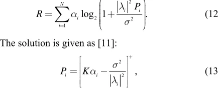
precod g matrix is chosen from [13] fore, the weighted sum rate is
here li are the diagonal elements of HV where the
in . There
2
2 2
1
log 1 .
N
i i i
i
P
R a l
s
=
æ ö÷
ç ÷
ç
= çç + ÷÷
÷
çè ø
å
(12)The solution is given as [11]:
2
2 ,
i i
i P Ka s
l
+
é ù
ê ú
=ê - ú
ê ú
ë û
(13)
which is also a waterfilling distribution with equal prior-ity.
In fact, the procedures of itera
presented before are based on the fact that the powers
i hould be found. Ther e, we should
re-e
r the proposed iterative waterfilling aterfilling (MMSE PMWF) found by exhaustive search
set to 0 dB. We can see that the optimum MMSE pre-co
tive optimization as
j
P for j¹i are known to obtain Pi. For this, a joint optim zation s
resul
efor pe
un
at the aforementioned waterfilling procedures to find each Pi by adjusting Pj values of the preceding step
til the ting rate converges after setting arbitrary initial values for Pj.
4. Simulation Results
In this section, w analyze the performance in terms of achievable rates fo
(MMSE PWF), modified w and the optimum solution
(MMSE ES). We also compare these performances to those of block-diagonalization using a waterfilling scheme (BD WF).
For these numerical results, the channel matrix entries are assumed to be independent identically distributed zero- mean complex Gaussian random variables with variance of 0.5 per dimension. The initial powers for the iterative WF and MWF have been set equal to the Pi of the
uni-form power distribution and the final power allocations are obtained after 5 iterations in all the simulations. For a fair comparison, SNR is defined as the ratio in dB of
2
maxBS /
P s .
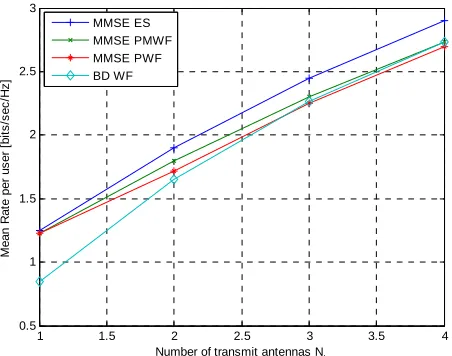
In Figure 4, we compare the different solutions in
terms of mean achievable rate for each user on the condi-tion that each user has the same priority and the SNR is
ding found by ES outperforms BD WF for all the val-ues of the number of transmit antennas Nt, and MMSE
[image:3.595.318.535.202.291.2]that requires a lengthy numerical optimization, in par-ticular at the low SNR.
In addition, we obtain the region of achievable rates for SNR=0 dB in Figure 5, where we show the effect of
the different power allocation schemes with MMSE pre-coding. We can see that MMSE PMWF obtains higher ac
e optimum power distribution can be ob-ta
hievable rates than MMSE PWF. As the number of transmit antennas increases, the difference between MMSE ES and MMSE MWF is larger. However, even if suboptimal, MMSE MWF outperforms BD WF as shown in Figure 1, without resorting to a lengthy numerical
optimization.
The main difference in terms of complexity between MMSE and BD approaches is coming from the power optimization procedure. From the simulation results, we can see that th
ined through a lengthy exhaustive search while water-filling approaches allow a highly reduced complexity at
1 1.5 2 2.5 3 3.5 4 0.5
1 1.5 2 2.5 3
Number of transmit antennas N
t
M
ean
R
a
te
p
e
r us
er [
b
it
s
/s
e
c
/
H
z
]
[image:4.595.61.287.314.492.2]MMSE ES MMSE PMWF MMSE PWF BD WF
Figure 4. Mean achievable rate for each user with equal probability, N=2 and SNR=0 dB.
0 0.5 1 1.5 2 2.5 3
0 0.5 1 1.5 2 2.5 3 3.5
mean Rate user 1 [bits/sec/Hz]
M
ean
R
at
e ues
r 2 [
bi
ts
/s
ec
/
H
z
]
MMSE ES MMSE PMWF MMSE PWF
Nt=3
Nt=2
[image:4.595.61.290.533.708.2]Nt=1
Figure 5. Region of mean achievable rates with N=2 and SNR=0 dB.
the expense of some performance degradation. Since waterfilling is performed over N user transmissions, it does not depend on the number of transmit antennas. Therefore, the complexity of PWF and PMWF is irre-spective of the number of antennas per BS. In addition, MMSE PMWF is a good choice in terms of the balance between complexity and achievable rates.
5. Conclusions
In this paper, we present feasible combinations of MMSE- based beamforming and iterative waterfilling power al-location schemes that can be applied to the downlink of a CBST system while they are required to take a tradeoff between complexity and achievable rates into
considera-ed with MMSE beamforming outperforms a
R regime.
ments
tion. In addition, we show that the iterative MWF alloca-tion combin
BD scheme that requires a lengthy numerical optimiza-tion in the low and moderate SNR regimes under a two-base station/two-user simplified scenario. Further-more, we show that our proposed iterative MWF scheme obtains a performance close to that of MMSE by exhaus-tive search at a high SNR regime as well as MMSE and BD have the same performance at a high SN
6. Acknowledge
This work was supported by the National Research Foundation of Korea (NRF) grant funded by the World Class University R32-2012-000-20014-0, the Korean government (MEST) 2012-002521, and BSRP 2010- 0020942 Korea.
REFERENCES
[1] M. Sawahashi, Y. Kishiyama, A. Morimoto, M. Nishi-kawa and D. Tanno, “Coordinated Multipoint Transmis-sion/Reception Techniques for Ite-advanced,” IEEE Wire-less Communications, Vol. 17, No. 3, 2010, pp. 26-34. doi.org/10.1109/MWC.2010.5490976
[2] D. Samardzija and H. Huang, “Determining Backhaul Bandwidth Requirements for Network MIMO,” 17th
Conference (EUSIPCO 2009, pp. 1494-1498.
European Signal Processing 2009), Glasgow, Scotland,
[3] W. Choi and J. G. Andrews, “The Capacity Gain from Intercell Scheduling in Multi-antenna Systems,” IEEE Transactions on Wireless Communication, Vol. 7, No. 2, 2008, pp. 714-725.doi:10.1109/TWC.2008.060615 [4] T. Ren and R. J. La, “Downlink Beamforming
Algo-rithms with Intercell Interference in Cellular Networks,” IEEE Transactions on Wireles Communincation, Vol. 5, No.10,2006,pp.2814-2823.doi:10.1109/TWC.2006.04580 [5] S. G. Kiani a al and Distributed
2008, pp. 288-297.doi:10.1109/TWC.2008.060503 nd D. Gesbert, “Optim
ology Conference
ultiplex-[6] S. Shamai (Shitz) and B. M. Zaidel, “Enhancing the Cel-lular Downlink Capacity via Co-processing at the Trans-mitting End,” IEEE Vehicular Techn
(VTC2001-Spring), Rhodes, Greece, 2001, pp. 1745- 1749.
[7] Q. H. Spencer, A. L. Swindlehurst and M. Haardt, “Zero-Forcing Methods for Downlink Spatial M
ing in Multiuser MIMO Channels,” IEEE Transactions on Signal Processing, Vol. 52, No. 2, 2004, pp. 461-471. doi:10.1109/TSP.2003.821107
[8] J. Zhang, R. Chen, J. G. Andrews, A. Ghosh, and R. W. Heath, “Networked MIMO with Clustered Linear Pre-coding,” IEEE Transactions on Wireless Communications, Vol. 8, No. 4, 2009, pp. 1910-1921.
doi:10.1109/TWC.2009.080180
[9] E. Bjornson, R. Zakhour, D. Gesbert and B. Ottersten, “Distributed Multicell and Multiantenna Precoding: Characterization and Performance Evaluation,” IEEE Global Communications Conference (GLOBECOM 2009), Hawaii, U.S.A, 2009, pp. 1-6.
[10] R. S. Cheng and S. Verdu, “Gaussian Multiaccess Chan-nels with ISI: Capacity Region and Multiuser Wa-ter-filling,” IEEE Transactions on Information Theory, Vol. 39, No. 3, 1993, pp. 773-785.
doi:10.1109/18.256487
[11] A. Garcıa Armada, M. Sanchez Fernandez and R. Corvaja, “Waterfilling Schemes for Zero-Forcing Coordinated Base Station Transmission,” IEEE Global Communica-tions Conference (GLOBECOM 2009), Hawaii, U.S.A, 2009.
[12] J. M. Cioffi, “Advanced Digital Communications, EE379c,” Stanford University Course Notes.
http://www.stanford.edu/class/ee379c.
[13] G. J. Foschini, K. Karakayali and R. A. Valenzuela, “Coordinating Multiple Antenna Cellular Networks to Achieve Enormous Spectral Efficiency,” IEEE
Proceedings Communications, Vol. 153, No. 4,