HONEYWELL
IDPS8
I
SITE PREPARATION
I
MANUAL
I
FOR DPS 8 SYSTEMS
SUBJECT
DPS8
SITE PREPARATION MANUAL
FOR DPS 8 SYSTEMS
Instructions for Preparing a DPS 8 System Site
SPECIAL INSTRUCTIONS
This is the original issue of DU34-00. This manual supersedes Site Preparation Manual, DN01-01, dated August 1982.
The following notice is provided in accordance with the United States Federal Communications Commission's (FCC) regulations.
Warning: This equipment generates, uses, and can radiate radio frequency energy and if not installed and used in accordance with the instruction manual, may cause interference to radio communications. The equipment manufactured after October 1, 1983 has been tested and found to comply with the limits for a Class A computing device pursuant to Subpart J of Part 15 of FCC Rules, which are designed to provide reasonable protection against such interference when operated in a commercial environment. Operation of this equipment in a resi-dential area is likely to cause interference in which case the user at his own expense will be required to take whatever measures may be required to correct the interference.
Includes Update Pages Issued as Addendum A in August 1986.
ORDER NUMBER
DU34-00 January 1986
PREFACE
The primary purpose of this manual is to assist you in planning
your system site. Remember, however, a successful installation
de pen d suI t i ma t.e I yon h ow we I I you a I 10 cat e i n d i v i d u a I
responsibilities and how carefully the overa) I site planning and follow-up work is performed.
This manual guides you through all phases of site preparation planning whether your engineering personnel or outside
consultants formalize the site preparation reQuirements. To
help achieve an efficient computer installation, observe closelY the design reQuirements and recommendations outlined in this manua I .
This manual includes information for site preparation planning, site facility reQuirements, and individual device specifica-tions.
A postpaid feedback remarks form is provided in the back of this
manual. Comments from the users of this manual are appreciated.
The information and specifications in this document are subject to change without notice. Consult your Honeywell Marketing Representative for product or service availability.
©Honeywell Information Systems Inc., 1986 FileNo.: 1VV3
TABLE OF CONTENTS
SECTION 1 INTRODUCTION . . . , . . . '" 1-1
1 . 1 Reference Documentation . . . 1-2
SECTION 2 SITE PLANNING . . . 2-1
2 .1 Site Preparation Tasks . . . 2-1
2.1.1 Cod eRe Qui r eme n t 5 . . . " 2 - 2
2.1.2 Site Selection . . . 2-3
2.2 Site layout . . . 2-5 2.3 Site Preparation Scheduling . . . 2-8
2.3.1 Preinstallation Schedule . . . 2-8
2.3.1.1 Ninety Days Before Delivery . . . 2-8
2.3.1.2 Sixty Days Before Delivery . . . 2-9
2.3.1.3 Thirty Days Before Delivery . . . 2-9
2.3.1.4 Seven Days Before Delivery . . . 2-10
2.4 Assu ranee Rev i ews . . . " 2-10
2.4.1 User Responsibil ity . . . 2-10
2.4.1.1 Status Before Ship Date . . . 2-11
2.4.1.2 Status Before Delivery Date . . . 2-12
SECTION 3 SITE FACILITY REQUIREMENTS . . . 3-1
3.1 Floor Requirements . . . 3-1
3.1.1 Cable Access Cutout Holes . . . 3-2
3 . 1 . 2 Floor Covering . . . 3-3
3.1 .2.1 Tile . . . 3-3 3.1 .2.2 Carpet . . . 3-4
3.1 . 2.3 Floor Mats or Runners . . . 3-4
3.1 . 2.4 Maintenance . . . 3-5
3.2 Wall and Ceiling Requirements . . . 3-6 3.2.1 Wa I Is. . . . .. 3-6
3.2.2 Ceilings . . . 3-6
3.2.3 Finishes . . . 3-6
3.2.4 Soundproofing . . . 3-7
3.3- Lighting . . . 3-8 3.4 Fire Protection . . . 3-8 3.5 Equipment Colors . . . 3-8 3.6 Media Storage Area . . . 3-9 3.7 Motor Generator Room . . . 3-10
3.8 Maintenance A.!"ea . . . 3-iO
3.9 Related Work Area . . . 3-10
SECTION 4 SITE POWER REQUIREMENTS . . . . 4-1
4.1 AC Power Requirements . . . 4-1 4 . 1 . 1 AC Power Specifications . . . 4-2 4.2 AC Power Distribution . . . 4-2
4.3 Motor Generator Specifications . . . 4-5
4.4 Uninterruptible Power System . . . 4-5
4.5 50/60 Hz Operation . . . 4-5
4.6 AC Power Requirements by Unit . . . 4-7
4.7 Phase Load Ba I anc i ng . . . 4-7
4.B AC Convenience Outlets . . . 4-7
4.9 Safety Emergency Power-Off Wiring . . . 4-B
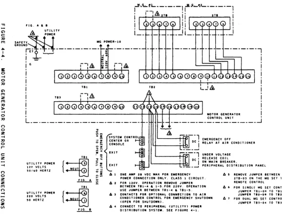
4 .10 Motor Generator Control Unit Wiring
Control Connections . . . 4-10 4.11 Grounding System . . . 4-10 4 .11 . 1 Earth Connection . . . 4-12 4.11.2 Safety Ground Wire . . . 4-13 4.11.3 Central System Signal Ground . . . 4-14
4.11.4 Floor Support Groending . . . 4-14
SECTION 5 SITE ENVIRONMENT REQUIREMENTS . . . 5-1
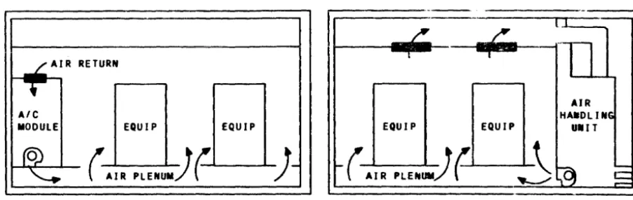
5.1 Cooling System Requirements . . . 5-1
5.2 Cooling System Capacity . . . 5-2 5.3 Air Flow Requirements . . . 5-2
5.4 Temperature and Humidity Monitoring . . . 5-4
5.5 Temperature Controls and Alarms . . . 5-4
5.6 Air Cleaning . . . 5-5 5.7 Balancing . . . 5-5
5.B Dust Control, Maintenance . . . 5-6
SECTION 6 SAFETY PRECAUTIONS . . . 6-1
6.1 General Precautions . . . 6-1
6.2 Personnel Training . . . 6-1
6.3 Fire Protection Equipment . . . 6-1
6.4 Fire Detection and Alarm System . . . 6-2
6.5 Emergency Lighting . . . 6-2 6.6 Lightning Protection . . . 6-2
SECTION 7 INSTALLATION PLANNING . . . 7-1
7 .1 System Electrical Requirements Summary . . . 7-1 7 . 1 . 1 General . . . 7-1 7.1.2 ReQu i rements . . . 7-2
7.2 Data Modem for Distributed Maintenance Service .... 7-B
7.3 System Environmental Requirements Summary . . . 7-10
7.3.1 General . . . 7-10 7.3.2 ReQu i rements . . . 7-10
7.4 Site Planning Templates . . . 7-56
FIGURES
FIGURE
2-1 Typical System layout (Example) . . . 2-7 4-1 Power System Diagram . . . 4-3
4-2 Typical Uninterruptible Power Supply Systems . . . 4-6
4-3 Safety Emergency Power-Off Switches Wiring . . . 4-8
4-4 Motor Generator Control Unit Connection . . . 4-9
4-5 System Ground Diagram . . . 4-11
5-1 Typical Computer Air Conditioning Examples . . . 5-3
7-1 Electrical Connections (Motor Generator) . . . 7-3
7-2 Electrical Connections (Transformer) . . . 7-3
7-3 Junct i on Box and Condu it . . . 7-4 7-4 Typical Receptacle Mounting . . . 7-4
7-5 legend for Installation Planning Drawings . . . 7-11
TABLES
TABLE
1-1 Reference Materials . . . 1-2 2-1 Installation Responsibilities . . . 2-1
3 - 1 S y s t em Color san d Chi p Numb e r s . . . . . . . . . . . . . . . . . . . . .. 3 - 9
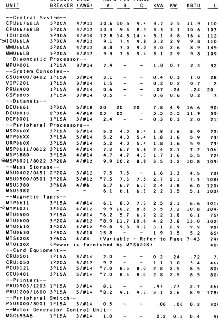
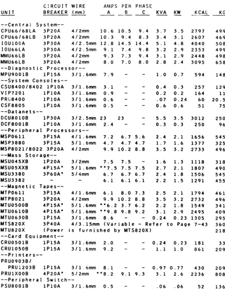
7-1 60 Hz Equipment Summary Data . . . 7-5 7-2 50 Hz Equipment Summary Data . . . 7-6
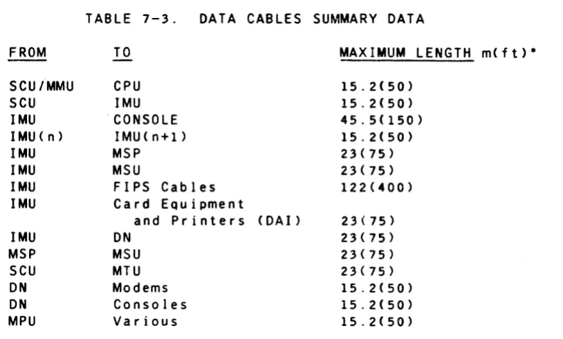
7-3 Data Cables Summary Data . . . 7-7
7-4 OMS Data Modem Opt ions . . . 7-8
7-5 Connection Symbols Used on Installation
PI ann i n9 Drawi ngs . . . 7-11 7-6 AC Power Wiring Color Codes . . . 7-12
7-7 Corresponding Standard Wire Sizes . . . 7-12
7-8 Site Planning Templates Order Numbers . . . 7-57
SECTION
1INTRODUCTION
The purpose of this manual is to assist the customer in site
planning and preparation for installation of the Honeywell DPS 8
Central System. The manual is divided into seven sections,
which are described below:
Section 1, Introduction, briefly outlines the contents of
the manual.
Section 2, Site Planning, describes the site planning tasks
from start to completion. The entire site preparation is
outlined.
Section 3, Site Facility Requirements, is intended to aid
you in selecting and preparing the area where your system is
to be installed. It provides information concerning the
space requirements, construction, lighting and other area requirements.
Section 4, Site Power Requirements, describes the system
power requirements and provides information pertinent to the installation of the primary power wiring.
Section 5, Site Environment Requirements, specifies the air
conditioning and air cleaning needs of the system.
Section 6, Safety Precautions, reco"mends safety procedures
and certain types of protective equipment which should be utilized on the system site.
Section 7, Installation Planning, consists of summary
information and Installation Planning Drawings. The
Installation Planning Drawings contain the specifications for Honeywell supplied data processing equipment which may be installed on your site.
It is suggested that you review this manual in its entirety
before starting your site plan. Honeywell representatives are
available to assist in interpreting this manual and to help in resolving situations not covered by this manual.
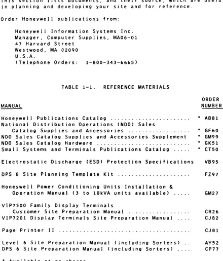
1.1 REFERENCE DOCUMENTATION
This section J ists documents, and their source, which are useful
in planning and developing your site and for reference.
Order Honeywell publications from:
Honeywell Information Systems Inc. Manager, Computer Supplies, MA06-01 47 Harvard Street
Westwood, MA 02090 U.S.A.
(Telephone Orders: 1-800-343-6665)
TABLE 1-1. REFERENCE MATERIALS
ORDER
MANUAL NUMBER
Honeywell Publications Catalog . . . . National Distribution Operations (NOO) Sales
Catalog Supplies and Accessories . . . . NDO Saies Cataiog Supplies and Accessories Supplement NDO Sales Catalog Hardware . . . . Small Systems and Terminals Publications Catalog .... .
Electrostatic Discharge (ESD) Protection Specifications
OPS 8 Site Planning Template Kit . . . .
Honeywell Power Conditioning Units Installation
&
Operation Manual (3 to 10kVA units available) ...
VIP7300 Family Display Terminals
Customer Site Preparation Manual . . . . VIP7201 Display Terminals Site Preparation Manual ... .
Page Printer II
Level 6 Site Preparation Manual (including Sorters) .. DPS 6 Site Preparation Manual (including Sorters) ....
• Available at no charge
• ABS1
• GF60 • GM99 • GKsl • CTsO
VB9s
FZ97
GM27
CR26 CJ82
CJ 81
Ays2 CP77
National Fire Code, National Electric Code, and NFPA references are available from:
National Fire Protection ASSOCiation Batterymarch Park
Quincy, MA 02269 U.S.A.
[image:8.620.64.505.71.587.2]2.1 SITE PREPARATION TASKS
SECTION
2
SITE PLANNING
A Honeywell representative must be contacted if any
characteristic of the site does not meet the requirements specified in this manual.
Before starting site planning and preparation, you may want to make such arrangement as you deem necessary for professional
consultant services. Also, Honeywell representatives are
available to assist you in planning your site; see Appendixes A
and B for guidelines and checklist. The site preparation
checklist must be utilized by CSD during all site preparation
activities. Appendix C contains Site Preparation Audit Report.
Table 2-1 outlines the sequence of events in Site Planning and
Preparation. It describes the steps to take and the assistance
Honeywell offers during system installation to customers who
lease or purchase their system directly from Honeywell. It does
not apply to any eQuipment designated by Honeywell as a customer
installable unit. In some cases, when a schedule changes, the
seQuence of events may vary.
TABLE 2-1.
WHAT YOU DO
Select the site for your
Honeywell computer system.
(Refer to Code ReQuire-ments in this section.)
Prepare the site.
(Refer to Code reQuire-ments in this section.)
SITE PLANNING
INSTALLATION RESPONSIBILITIES
WHAT HONEYWELL DOES
Honeywell representatives can help yOU decide among possible sites (existing or new) and help determine the applicability of the selected
site for the layout. Using building
specifications yOU supply, Honeywell can help you develop a system layout.
This manual provides site-related product specifications for the use of your plant engineer, architect, or
outside consultant in instal ling the
air conditioning and electrical power reQuired for your particular system and its associated peripherals.
Before system delivery, a Honeywell Customer Services Site Planner can audit your completed site, per Appen-dix C, to help ensure a successful
installation.
WHAT YOU DO
Agree with Honeywell on a shipment date for the system (a tentative shipment date should be established at the time the contract is signed).
Alert your Honeywell Marketing Representative
if delivery impediments exist or are anticipated (e.g., small elevator, second floor delivery, no receiving dock, etc.).
Accept the delivery and record any damage to the equipment or containers Declare exceptions
before signing to accept
delivery. Notify your
Honeywell Representative upon system arrival. The carrier (van) ines only) is to move all equipment including those in cartons or on
skids andlor pallets
into the computer area. This equipment must be
removed from the
cartons, off the skids and pallets, then placed in accordance with the plan layout.
Install any special
length or custom cables.
2.1.1 CODE REQUIREMENTS
WHAT HONEYWELL DOES
System components are carefully packed and readied for shipment from the factories to your site. Honeywell ordinarily selects an
independent carrier and method of delivery.
If the carrier is selected by
Honeywell, Honeywell will notify the carrier of anticipated delivery
problems.
When your equipment arrives, Honeywell Customer Services will:
o Supervise unpacking and positioning of all Honeywell eQuipment in
accordance with your layout.
o Inspect cable routing, physically connect approved standard length Honeywell interconnecting signal and control cables and, where applicable, connect the ac plugs.
o Check out the system by performing certain test and verification
routines.
It is important that both local and national code requirements
be adhered to in the construction of your site. National codes
are contained in the National Electric Code, NFPA 70 and the
Standards for Protection of Data Processing Equipment, .NFPA 75.
local codes should be obtained from your local building inspection department.
2.1.2 SITE SELECTION
The selection of the site for your Honeywell computer system is one of the most significant factors in planning and preparing for the installation.
The choice of a location for the computer facility should be
based on the applicable requirements for: aggregate space,
clearance and floor load for the computer and peripherals; air conditioning, electrical power, safety and fire prevention equipment; support functions and equipment; audible noise levels; adequate delivery capabilities; storage space and
expansion of the system. These considerations apply to both new
and old buildings.
Outlined below are some major site considerations that should be answered prior to selecting your computer site.
YOUR HONEYWELL COMPUTER EQUIPMENT MUST NOT BE
OPERATED WITH CONDENSED MOISTURE PRESENT OR
IN A DUST-LADEN OR CORROSIVE ATMOSPHERE.
o Is space available to house the air conditioning equipment: the compressor, air handlers, evaporators, condensers, and cooling tower eQuipment?
o Is electrical power available and adequate? Are outlets
sufficient as to type and location?
o Is there a separate room for the motor generator, (MG)? (This
is not applicable where the MG is not required such as when the customer is furnishing an uninterruptible power supply, or the ride-thru OPtions are installed.)
o Is the lighting adequate?
o Is the floor of the computer area structurally adequate to sustain the weight of the computer together with any other loads that may be imposed on it, or will floor load limits be exceeded?
o The U.S.A.standard 8 ft (2.5m in some countries> ceiling from
the top of the raised floor is ordinarily satisfactory for the Honeywell systems described in this manual.
o Do the surrounding walls and ceiling have any type of existing acoustical treatment to help reduce noise?
o Are permanent walls and partitions located to help reduce nOIse?
o Is accessibility for unloading the delivery van adequate?
o If the building (or facility) is more than one story high, is elevator accessibility and capacity adequate?
o Are there any building modifications necessary before moving in the computer equipment?
o Is the air filtration system (air cleaners) adequate?
o Is the fire and smoke detection system adequate?
o Is the fire extinguishing system adequate?
o Are support function areas (e.g., office space, media storage and equipment maintenance area) satisfactory?
o Are the related work areas suitable?
o Are the size and location of entrances and exits adequate for equipment delivery?
o Is there room for growth? Can new equipment be added, when
necessary, without causing radical changes to the currently allocated space?
o Does the site selection minimize, to the extent practicable, the possibility of loss or damage due to "Acts of God" or the negligence of others?
Some additional factors you might consider are:
o Insurance costs can be affected by the type of building
construction used and by the location of the site in relation to fire hazards and firefighting facilities.
o Zoning regulations may affect site location, construction, use and expansion.
o Before finalizing your site plans, investigate the building codes for your area; these often require that your drawings be approved by a locally licensed architect andlor city engineer.
o Existing customer facilities andlor operations may be
disturbed temporarily by the installation of Honeywell computer and data communication equipment.
o Electromagnetic interference (EMI) sources in the proximity of the computer system may have an adverse effect on computer system operation.
o Communications facilities should provide for future expansion of data communication equipment.
After your computer site has been selected, the following factors are worthy of consideration:
o Work flow - For efficient work flow, consideration should be
given to related work areas, human factors, storage, and noise isolation.
o Service area - Space should be provided near the system for
equipment supplies and media storage.
o Security - To protect both data and equipment, security
measures are essential. You may want to consider:
- Physical Security - Site access, fire and other damage
controls, including controlled personnel access.
- Control and Procedures - The audit of personnel, clearly
defined areas of responsibility, followed by controlled access to the computer system areas.
- Recovery and Backup Procedures - The protection of record
storage to help ensure continued operation, duplication and safe storage of priority, sensitive and crucial data.
2.2 SITE LAYOUT
Once your site has been selected, you should proceed with
developing the drawings for the site layout. Specific
considerations for designing an efficient processing center vary from installation to installation, but five major considerations for space and specifications apply to most installations:
o Do not underestimate growth potential. The trend has always
been for additional computer applications; this means additional equipment and, in turn, additional space.
o Make sure that the equipment is situated for the best operating efficiency and comfort.
o Deviations from the recommended environmental specifications or requirements included in this manual may cause serious problems in the operation and maintenance of the equipment.
o To prevent loss ~f processing r:=-n::.n;l;tv Ii"",;""" " n l t : a n A
- - ... - -. . . 3 ,...~ • . . . . : . """.&"''-A':r''''
reductions or brownout, power isolation and voltage regulation may be required.
o When applicable, space in the computer room must be allotted for a Maintenance Processor Unit (MPU) and for at least one site spares storage/maintenance cabinet.
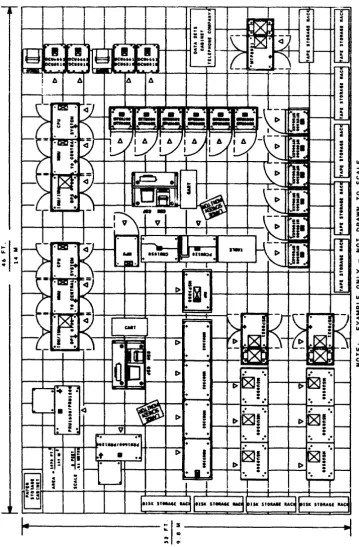
After evaluating the possible sites, you should prepare
equipment layouts for each area under consideration. A Site
Planning Template Kit (Order No. FZ97) is available for you to
order. Figure 2-1 is an example of a site layout using the Site
Planning Template Kit. The Site Planning Template Kit is made
to scale Your Honeywell representative is available to assist
you in developing your site layout.
You may order the Site Planning Template Kit, FZ97, from:
Honeywell Information Systems Inc. Manager, Computer Supplies, MA06-01
47 Harvard Street
Westwood, MA 02090 U.S.A.
The following details should be shown on the site layout drawing:
o Size and shape of the computer room.
o Entries and exits. (Doors should open outward.)
o Adjacent corridors size, elevators. ramps and staircases.
o Building columns, internal and external windows.
o Any underfloor or above-floor obstructions that may affect the installation or routing of interconnecting cables.
DO NOT EXCEED THE MAXIMUM PERMISSIBLE CABLE
LENGTHS IN DESIGNING THE SYSTEM LAYOUT.
AN
ALLOWANCE MUST BE MADE FOR A STUBOUT LENGTH
FOR EACH END OF THE CABLE.
o Location of the central system(s) and all peripherals.
o If used, location of motor generator control unit or uninterruptible power system control unit in the computer
room.
o Location of motor generator or uninterruptible power system, if used.
o Emergency power-off switches.
:: s
: !
::1:
.....
.~
FIGURE 2-1. EXAMPLE OF A SITE LAYOUT USING
THE SITE PLANNING TEMPLATE KIT
[image:15.617.98.458.116.664.2]o Circuit brertker load centers.
o The ac ground point and the system ground point.
o Site storage and maintenance cabinet locations.
o Media storage area.
o Related work tables and an area for carts.
o Communication terminals, communication data sets, and data modems.
2.3 SITE PREPARATION SCHEDULING
2.3.1 PREINSTALLATION SCHEDULE
After you have selected the equipment complement that suits your requirements, establish a schedule incorporating all phases of
preinstallation and system installation work. Although it
should be understood that scheduling concerns and timeframes may vary depending upon particular circumstances, a typical
preinstallation schedule for a Honeywell computer system follows.
2.3.1.1 NINETY DAYS BEFORE DELIVERY
You and the Honeywell representative should establish a
preliminary drawing that shows the intended arrangement of the
equipment at the selected site. The site layout should be
approved by you, Honeywell Customer Services and the Honeywell Marketing Representative before starting site construction.
After site layout approval, the following steps are typical:
o Verify site dimensions and building access dimensions.
o Review and order any necessary accessories to support your
operation. Your order for data modems, data sets and
telephones should be placed as early as possible to ensure all telephone communication equipment is installed before
equipment delivery.
o Ensure that the proposed floor loading meets the building specifications and applicable city codes and ordinances.
o Determine the location and type of the primary power source
(in-plant diesel generator, public utility, etc,) and the
length of power runs.
o Determine the eiectricai power source capacity and Quality vs. the system needs.
o Arrange for the installation of any necessary additional electrical power.
o Determine the voltage fluctuations at the power service
entrance over a one week period. (A power analyzer should be
used for this purpose.) If the voltage fluctuations are
greater than the eQuipment specifications. voltage regulation is required.
o Determine if additional air conditioning is necessary and arrange for installation.
2.3.1.2 SIXTY DAYS BEFORE DELIVERY
Honeywell Customer Services should be provided with approved copies of the site layout drawings and specifications, including accesses, docks, door sizes, elevator sizes, etc.
o Order circuit breaker load center(s) and raised flooring.
o Establish a plan to vacate the selected site if it is presently occupied.
o Arrange for insurance you may need for your computer site.
o If you wish to purchase supplies from Honeywell, you should place your order at least 30 days before equipment delivery. Order from the Honeywell National Distribution Operations Sales Catalog Supplies and Accessories, Order Number GF60, and Supplies and Accessories Supplement. GM99.
2.3.1.3 THIRTY DAYS BEFORE DELIVERY
o Install primary power equipment, MG(s), MG control unites), uninterruptible power supply system, etc.
o Install ac power.
0 Install ground braid and ground wiring.
0 Install earth ground.
0 Install lighting fixtures.
0 Install air conditioning.
0 Install fire and smoke detection system.
o Install fire extinguishing system.
o Install raised flooring.
o Verify that all accessory equipment, such as data m6dems, data sets, remote terminals, teleprinters, and communication lines function properly.
o Complete the support facilities (such as media storage and Customer Services maintenance area).
o Ensure that a data modem (Honeywell DCD2124 or equivalent) and telephone are available for the Distributed Maintenance
Service (OMS). The OMS Data Modem Options information is
included in Section 7.
2.3.1.4 SEVEN DAYS BEFORE DELIVERY
All electrical and structural elements of the site should have been installed and checked out, including air conditioning, fire and smoke detection system, fire extinguishing system and the raised flooring.
2.4 ASSURANCE REVIEWS
2.4.1 USER RESPONSIBILITY
It is your responsibility to prepare the facility from start to finish so that the equipment can be installed, operated and
maintained as outlined in this manual. Refer to the following
two lists. The first includes overall readiness of the computer
site and building facilities prior to ship date.
The second list involves the computer area, building access, rigging and carrier packing arrangements prior to delivery date.
IMPORTANT
THE CUSTOMER SHALL INSTALL, AT NO EXPENSE TO HONEYWELL, AND SHALL BE SOLELY RESPONSIBLE FOR, ALL INTERNAL
BUILDING WIRING INCLUDING POWER AND SPECIAL SIGNAL CABLES (NOT RESTRICTED TO THE COMPUTER ROOM IN WHICH THE EQUIPMENT IS INSTALLED), IN ACCORDANCE WITH THE NATIONAL ELECTRICAL CODE AND ALL LOCAL CODES,
REGULATIONS AND REQUIREMENTS.
2.4.1.1 STATUS BEFORE SHIP DATE
o CONSTRUCTION ( i f applicable)
- New dry wall installed, painted, etc.
- Doors and windows installed.
o Lighting installed.
o ELECTRICAL
Electrical power eQuipment and wiring installed according to specifications.
- Convenience outlets working.
- Transformers and voltage regulators wired correctly.
- Communication and interconnecting cables installed; e.g.,
data modems, data sets, teleprinters, remote terminals and
telephones. (Contact your local telephone communications
representative.)
- Power receptacles or connectors available and installed.
o AIR CONDITIONING
- Ensure that the cooling capacity and humidity control of the
system is adeQuate to meet the design environmental specifications.
- Ducts and air filters clean.
o GENERAL FACILITIES
- Fire protection facilities installed.
= Data storage area complete.
Elevators reserved and checked for carrying capacity.
- EQuipment delivery access route through the building
established and checked for clearance dimensions.
- Rigging arrangements and street availability checked for
permits.
2 4.1.2 STATUS BEFORE DELIVERY DATE
o CONSTRUCTION
- Card, tape, printer paper an~ disk media storage facilities
completed.
- Raised floor cutouts cut and floor panels reinstalled.
- All computer areas clean and free from dust.
o ELECTRICAL
Circuit breaker load center(s) wired, correct size breakers installed and checked out for each device.
- Conduit (when used) installed.
- All wires pulled through conduit from circuit breaker load
center to the appropriate junction box. Proper device and
power connectors or recePtacles installed.
- Ensure that proper grounding techniques for the system are
used. 00 NOT USE THE CONDUIT AS A GROUND CONNECTION.
- Data modems and data sets installed and wired properly.
(Contact your local telephone communications representative. )
o AIR CONDITIONING
- Cooling and air circulation checked out.
- Humidity and temperature controls checked out.
- Air vents and registers installed and checked out.
o GENERAL FACILITIES
- Elevators reserved and marked accordingly.
- All access routes checked for clearance and accessibility.
All obstructions should be clearly marked.
- Carrier parking permit secured.
- Carrier and rigging company schedule checked.
- Carpets andlor raised floor should be protected during
moving in or out of equipment {lSmm (5/8 in.> plywood should
be adequate). This should be arranged with the carrier
prior to equipment delivery.
IMPORTANT
DURING THE FACILITY PLANNING PHASE, A HONEYWELL REPRESENTATIVE IS AVAILABLE TO REVIEW THE SITE PREPARATION PLANS THAT HAVE BEEN MADE BY YOUR
FACILITIES PERSONNEL OR CONTRACTOR. YOUR HONEYWELL
REPRESENTATIVE CAN EVALUATE THESE PLANS TO HELP ENSURE THEIR CONFORMANCE WITH THE REQUIREMENTS OF THE COMPUTER SYSTEM YOU HAVE SELECTED.
DURING THE COURSE OF SITE PLANNING, SITE PREPARATION AND SYSTEM INSTALLATION, HONEYWELL IS AVAILABLE TO CONDUCT PERIODIC PROGRESS REVIEWS WITH YOUR FACILITIES PERSONNEL OR CONTRACTOR TO HELP ENSURE THAT PLANNING AND PREPARATIONS ARE PROCEEDING AS REQUIRED AND IN A MANNER CONSISTENT WITH A SMOOTH, EFFICIENT
INSTALLATION.
A REVIEW BY HONEYWELL WILL ORDINARILY BE MADE SHORTLY BEFORE SHIPMENT OF THE SYSTEM TO HELP ENSURE THAT ALL IS IN READINESS FOR AN EFFICIENT AND COMPLETE
INSTALLATION. EXPERIENCE HAS SHOWN THAT IT IS TO YOUR ADVANTAGE TO HAVE ALL SITE PREPARATIONS COMPLETED
BEFORE RECEIVING YOUR SYSTEM. THE HONEYWELL
REPRESENTATIVE CAN, WITH THE HELP OF YOUR FACILITIES
PERSONNEL OR CONTRACTOR, EXAMINE YOUR PREPARATIONS. IF
WORK IS NOT COMPLETE, HE OR SHE WILL WORK WITH YOUR REPRESENTATIVE TO ARRIVE AT A NEW SCHEDULE FOR
COMPLETION AND SHIPMENT OF YOUR SYSTEM.
HOWEVER. THE FAILURE OF HONEYWELL TO DETECT OR NOTIFY
YOU OF ANY NONCONFORMANCE TO SITE PREPARATION OR LAYOUT PLANS OR TO SITE SPECIFICATIONS OR REQUIREMENTS OR
RECOMMENDATIONS DOES NOT RELIEVE YOU OF ANY CONTRACTUAL OR OTHER RESPONSIBILITY THAT YOU MAY HAVE WITH RESPECT
;0 SITE PREPARATION AND SYSTEM INSTALLATION NOR SHALL
HONEYWELL BE LIABLE FOR FAILURE TO DETECT OR NOTIFY YOU OF SUCH NONCONFORMANCE.
SECTION 3
SITE FACILITY REQUIREMENTS
IMPORTANT
THE FOLLOWING RECOMMENDATIONS AND REQUIREMENTS ARE SUBJECT TO APPLICABLE LOCAL CODES, REGULATIONS AND ORDINANCES, WHICH, IN THE EVENT OF ANY CONFLICT OR
INCONSISTENCY, WILL CONTROL AND PREVAIL OVER THE FOLLOWING RECOMMENDATIONS.
3.1 FLOOR REQUIREMENTS
The system is designed for underfloor access of power and logic
cables. The customer should provide a raised floor or its
equivalent. The raised floor must meet the following
requirements:
o Minimum height between subfloor and raised floor of 200mm (8 in.), or 300mm (12 in.) if used as an air plenum.
o A ramp rise of 85mm to 100mm per meter (one inch to 1-3/16 inches per foot), approximately 5 degrees, is recommended.
This is defined as a Class A ramp. The ramp must not exceed
20 degrees. All mainframe units require support on ramps
greater than 15 degrees.
UNITS MARKED "TRANSPORTATION TIP
HAZARD-REQUIRE SPECIAL HANDLING ON STEEP RAMPS TO
ENSURE SAFETY OF PERSONNEL AND EQUIPMENT.
o Level within 6mm (1/4 inch) within 3m (10 ft).
o Floor loading capacity shall be capable of sustaining:
Leveling pad - 35kg/sQ cm (500 Ibs/sQ in.) maximum.
Caster - The casters on some equipment may impose a higher
point loading on the floor than the floor design specifies, therefore it is recommended that the raised floor be
protected (such as using plywood) while moving heavy equipment into place.
- Maximum load of any single unit - 1000 kg/sQ m (200 Ibs/sQ ft) (weight of the unit divided by the area actually
occupied by the unit).
- The distributed floor load for the entire system may be
calculated by adding the weights of all units to be
installed, including auxiliary equipment and dividing by the total area of the computer room.
IMPORTANT
THE METAL FRAME SUPPORTING THE FALSE FLOOR MUST HAVE A SOLID BUILDING GROUND AS SPECIFIED UNDER
GROUNDING SYSTEM IN SECTION 4.
If power receptacles located under a raised floor are exposed to
water, waterproof connectors must be used. Proper drainage must
be provided to guard against flooding or trapping water under
the false floor in the computer room. This is especially
important in buildings where the regular floor is depressed and the raised surface is level with the adjacent areas.
If carpeting is used, it must be of a type specifically
manufactured for computer room application and be rated at 2.0kV
or less at 70°F (21°C) and 20% humidity.
3.1.1 CABLE ACCESS CUTOUT HOLES
TO PREVENT INJURY TO PERSONNEL OR CABLE
DAMAGE, THE CUTOUT HOLE EDGES MUST BE
DEBURRED OR LINED WITH VINYL MOLDING STRIPS
OR GROMMET.
CARE MUST BE TAKEN DURING THE PERIOD BETWEEN
CUTTING FLOOR HOLES AND INSTALLATION OF THE
EQUIPMENT TO ENSURE THAT THE HOLES ARE
TEMPORARILY COVERED TO PREVENT ACCIDENTAL
INJURY TO PERSONNEL.
A drawing of each cabinet base, included in Section 7, can be used to locate cutout holes for system cable access and ac power
cables. Using these drawings as a guide, the computer room
floor access holes can be cut prior to delivery of the system. Cutout hoie edges must be prepared in a way that will prevent
cable damage. Floor panel manufacturers can provide vinyl
moiding strips for lining the cutout holes.
The scaled template set~ FZ97, can be provided by your Honeywell
representative.
After system installation on sites with und~rfloor air
conditioning, the ac power and logic cable access holes must be blocked off in an appropriate manner with UL approved
nonflammable material to prevent uncontrolled air flow. This is
essential to balance air flow effectively and to prevent air at too Iowa temperature from entering the units.
3.1.2 FLOOR COVERING
Many considerations besides appearance and cost determine the
best floor covering material for a computer installation. For
example, materials that produce or trap lint and dust or reQuire much water to clean pose a direct hazard to the eQuipment
installed in the area. Certain materials are more prone to
generation of static electricity and should be avoided. A
conductive flooring is recommended. Special conductive flooring
materials include terrazo, vinyl tile and carpet .
3.1 .2.1 ... 'I' I l
-I 1 L~
Honeywell considers high-pressure laminated fiber-resin floor
s~rfacing material to be a superior product for raised flooring
computer installations. The extremely hard surface is highly
resistant to scratching, scarring, denting and cigarette burns. Also, it possesses excellent color stability and glare control. These surfaces do not ordinarily require waxing and need only an occasional damp mopping.
In computer areas where raised flooring is not used, conductive
vinyl or terrazo tile should be used. Examples of material that
should not be used are: asbestos-filled vinyl which may present
a health hazard and asphalt tile because it chips easily.
producing dust that could cause equipment problems.
3.1.2.2 CARPET
UNDER SOME FIRE CODES, CARPETING IS NOT
ALLOWED IN COMPUTER AREAS.
Carpeting offers many advantages over tile. A good grade of
carpet can be treated to be lint free and lasts as long as good vinyl tile, but a poor grade of carpet can wear rapidly and produce great amounts of lint that may damage the equipment. Carpeting is attractive and serves as an excellent sound
suppressor. It also is more comfortable for operating
personnel.
Carpeting may be permitted if it will not contribute to the spread of fire, is not readily ignited by sparks or burning embers, and does not restrict lifting the panels for access to the underfloor space.
Provisions must be made to prevent a buildup of static
electricity, beginning with the selection of the carpet fiber. Pure nylon carpet, for example, is unacceptable because of its
static attraction. Be sure to select carpeting with permanent,
built-in static protection which limits static buildup to less
than 2kV at 20% relative humidity and 700F (210C). When the
carpet is installed on access floors, its electrical resistance from surface to ground should be no higher than 250 kilohms to help provide both personnel safety and good static performance.
Keeping the humidity within specifications will further minimize
static buildup. In existing static producing carpeted areas,
one of the anti-static spray products can be an effective
treatment to minimize static. However, this treatment must be
repeated on a regular basis.
3.1.2.3
FLOOR MATS OR RUNNERS
Electrically conductive floor mats or runners can be used in
areas requiring localized protection against static. Honeywell
has determined that electrostatic discharge (ESO) produced by
static electriCity may upset the logic in your computer,
minicomputer, terminal subsystems, processing stations or other
related computer equipment. Carefully locate floor mats or
runners in your computer area so that any static charge can be
harmlessly eliminated from personnel who enter the area. Mats
should be placed wherever operators are likely to step before actually touching the equipment.
For example:
o Around all computer work stations, data entry terminals, minicomputers and processors.
o As a runner at the entrance to data processing areas
(especially if the area is entered from a carpeted floor).
o As a runner in front of a row of peripherals, such as tape handlers and disk drives.
o Around any sensitive peripherals in the data processing area where contact with operating personnel is freQuent.
For additional information on static electricity, send for the pamphlet, Electrostatic Protection in the Computer Equipment Environment, Honeywell Order Number VB95 (see Paragraph 1.1).
3.1.2.4 MAINTENANCE
NEVER ALLOW STEEL WOOL POLISHING PADS TO BE
USED IN THE COMPUTER ROOM.
Place tack rugS at all entrances to eaten dust, grl1 ana
abrasives brought in from other areas. Daily removal of loose
traffic dust can help minimize the risk of damage to the computer equipment.
Water must not be used freely for cleaning because of the
possible electrical shock hazard involved. On raised floor,
water can seep between the floor panels and damage the cables
below. For tile floors, a well-wrung mop or a vacuum cleaner
may be used, but the preferred method is to use clean dust absorbing cloths which are often available on a rent-exchange
basis. The method removes dust without stirring it up. On
carpet, use a tightly sealed vacuum cleaner with a good filter.
With raised floors, be sure that lint from scrub brushes and airborne particles or corrosive cleaning agents do not seep
between the panels where they can be drawn into the equipment by
their internal circulation fans. Periodic cleaning of the
subfloor area is recommended to prevent dust and debris from accumulating.
3.2 WALL AND CEILING REQUIREMENT~
3.2.1 WALLS
Perimeter walls must be installed between the subfloor and the
permanent cei ling. Partitions within the computer area complex
should be installed between the raised floor and the ceiling. Partitions lower than ceiling height should be avoided to
minimize dust and noise in the area. If partitions are
installed betweer adjacent raised floor areas, they should clear the subfloor by at least 140mm (5.5 inches) along their base, except at post locations, or they should rest on the raised
floor. This allows clearance for interconnecting cables and for
power conduits.
Consider the use of movable steel partitions which are usually
80% reusable and can be provided with a one hour fire rating, a
broad range of prefinished colors and surface materials and with effective acoustical treatment.
All computer room doors should open outward and be fire
resistant. The outer walls should be fireproof.
3.2.2 CEILINGS
The USA standard 8 ft (2.5m in some countries) ceiling as measured from the top of the raised floor is satisfactory for
the Honeywell computer systems described in this manual.
Any commercial grade of fire resistant ceiling tile is usually
adequate. Your architect or consultant can recommend ceiling
materials which require minimal maintenance and may help reduce the cost of heating, lighting and air conditioning.
Acoustic treatment of the ceiling is advisable. Sprayed on
acoustical ceilings and mineral based fissured, dropped ceiling
tiles should be avoided because they flake. Dropped or
suspended ceilings generally have the best combination of noise
absorption characteristics, appearance and low maintenance. A
perforated metal pan ceiling with a sound absorption backing pad or matte-faced fiberglass is desirable.
3.2.3 FINISHES
The finish of the walls and ceilings should be free from flakes,
chips and chalking materials. Do not install glassfiber tiles
that might produce abrasive particles. Avoid using any paint
that powders 0r flakes.
3.2.4 SOUNDPROOFING
A computer area has a higher noise level than a clerical office
containing light office equipment. To keep the noise in the
computer area and nearby areas to an acceptabie ievel, pay
particular attention to the use of sound absorbing materials and
to the arrangement of barriers that wili defiect sound. To
isolate the area acoustically, the perimeter walls should be
heavy and as free from cracks and openings as possible. Open
doors, for example, destroy acoustic isolation.
Partitioning is usually sufficient to reduce the sound level in
adjacent offices to an acceptable range of 50 to 55 decibels.
Quiet study or conference rooms should not be located near the computer equipment.
It is normal practice to provide an acoustical ceiling suspended
below the structural ceiling. See CEILINGS in this section for
details.
In some installations, acoustic treatment of the walls may be
also required. Take care that the materials chosen are durable.
Heavy curtains (over walls or windows) are acoustically
effective but require removal for cleaning. For window areas
where light is desired, tilted venetian blinds may substitute for closed curtains. The vanes of the blinds reduce the direct reflection of sound.
Untreated surfaces that are broken by columns, decoration or irregular room shapes disperse sound better than flat surfaces.
Structure borne vibiation that causes noise in areas adjacent to or below the computer area is usually negligible unless the
floor is in very poor condition. Raised floors should have
extra support jacks at strategic places to prevent transmission of vibration along the surface.
In some installations, where the air conditioning fan is close to the computer area, some special treatment may be required to reduce its contribution to the area noise level.
Your architect or consultant can suggest some of the more
popular soundproofing materials for your consideration. Check
with your contractor about the reactive noise reduction
coefficients of available materials. Materials are preferred
which have significant absorption properties at the lower
frequencies (125-250 Hz bands> as well as at the higher
frequencies.
When special problems exist and the installation of acoustic material reQuires special techniques, consult a specialist.
3.3 LIGHTING
An intensity of approximately 861-1076 lux (SO-100 footcandles)
at desk level is ordinarily adequate for the computer area. Fluorescent lighting is preferred because it generates little
heat and illuminates the work area evenly. Personnel operate
switches, read indicators, read video displays, etc., therefore,
the room must be free of glare. This should be considered in
the design and position of the lighting fixtures. Flush or
recessed fixtures are suggested since they are attractive and are less likely to collect dust than hanging fixtures.
Direct sunlight should be avoided because a lower level of illumination is needed to observe the indicator lights on the
equipment. Also, light sensitive sensors are used in certain
Honeywell computer equipment and the sunlight can cause false
reactions. Windows which receive sunlight should be fitted with
venetian blinds, glazed with tinted glass or treated with other material to protect against sunlight.
Even when not required by code for certain areas, some type of
emergency lighting should be provided. Emergency lighting can
be of the ordinary battery operated type, that turns on automatically when power to the main lighting system is
interrupted. These units are wired to and controlled by the
lighting circuit and are activated by a relay or a light sensor.
3.4 FIRE PROTECTION
Permanent fire protection equipment should be installed during
the construction phase of your site preparation. Information is
given in Section 6 concerning fire detection and fire
extinguishing equipment.
3.S EQUIPMENT COLORS
Customer selected Standard or Optional accent color is applied within the system to specific units preselected by Honeywell to
enhance the appearance of the operating environment. Optional
colors are available on an RPQ (Request Price Quote) additional
cost basis.
Color chips are available for use by the customer or
subcontractors for color matching computer room accessory
equipment and decor. They may be ordered from:
Honeywell Information Systems Inc. Finish Control Center
200 Smith Street
Waltham, MA 02154
U.S.A.
(Telephone 617-895-6098)
Order by color name and chip number as given below:
TABLE 3-1. SYSTEM COLORS AND CHIP NUMBERS
SYSTEM COLOR
STANDARD Color Scheme Accent P-1
STANDARD Color Scheme Accent P-2
OPTIONAL Color Scheme Accent P-3
OPTIONAL Color Scheme Accent P-4
OPTIONAL Color Scheme Accent P-5
3.6 MEDIA STORAGE AREA
Gothic Black Executive White Caribbean Blue
Gothic Black Executive White Hunter Red
Gothic Black Executive White Aztec Yellow
Gothic Black Executive White Maritime Green
Gothic Black Executive White Rebel Red
CHIP NUMBER
58000100-003 58000100-703 58000100-001
58000100-003 58000100-703 58000100-004
58000100-003 58000100-703 58000100-005
58000100-003 58000100-703 58000100-006
58000100-003 58000100-703 58000100-265
Media must be stored conveniently and under proper environmental
conditions. Depending on the size of YOur computer
installation, space must be allotted for the storage of tab cards, printer paper, magnetic tapes, disk packs, printer
ribbons and other supplies. Savings in operator time over the
life of the system can justify dedication of sufficient storage space convenient to the point of use.
Consider fireproof storage for critical magnetic tapes and disk
packs. The amount of space to be allotted for disk pack storage
depends upon the total number of disk packs reQuired by the system and the possible division of these disk packs into two or
more storage areas. Users normally desire a disk storage area
within the processing center for the current disk packs. You
may want to duplicate current disk packs as a safety factor in case of fire or loss of information through operator or machine
errors. If duplicate disk packs are used, provide a second disk
pack storage facility in a remote area.
The disk packs can be stored in any of several size cabinets
(housing 8 to 12 disk packs per cabinet). The recommended
storage positions for disk packs is flat in a horizontal position.
All media storage areas must be temperature and humidity controlled within the same limits as for the computer system.
[image:30.620.127.484.78.387.2]3.7 MOTOR GENERATOR ROOM
If you have or are planning for a motor generator for your site,
it is recommended that it be located in an adjacent room. There
should be approximately .9m (3 ft) clearance on all sides of the
MG. (Refer to the Installation Planning Drawings for the MGs in
Section 7.) The room must have clean ventilating air within the
limits of -laoC to 400C (OoF to I040F) and relative humidity of
5% to 95%, with sufficient air circ~lation to dissipate the heat.
3.S MAINTENANCE AREA
An area must be provided for maintenance work and for the
storage of spare parts and maintenance equipment. It should be
an enclosed area capable of being secured from unauthorized access and should be adjacent to the computer room at the same
floor level. If necessary, a ramp suitable for movement of test
equipment must be provided. For a single system, the area must
be at least IS.6m 2 (200 ft 2 ), or for a dual system, the area must be 23.2m 2 (250 ft 2 ).
The following facilities should be provided in the maintenance
area to facilitate efficient maintenance of your system:
o A workbench with a wooden top.
o A standard office desk.
o
A
four drawer filing cabinet.o A desk chai, and a steel posture stool.
o Two duplex convenience outlets, (120V, 20A for 60 Hz) or
(220V, 16A for 50 Hz).
o A telephone
o Standard office level lighting.
3.9 RELATED WORK AREA
You should allot space in your site layout for carts, tables and
storage racks for use by your operators and programmers. It is
recommended that decollating equipment and tab punch operations be located in a different room from your computer, as should any pickup/drop off area for the computer jobs, printouts, etc.
4.1 AC POWER ·REQUIREMENTS
SECTION
4
SITE POWER REQUIREMENTS
You must furnish and install utility power for the computer site
in accordance with the system power schematic, Figure 4-1. It
is also your responsibility to furnish and install the
electrical equipment for the installation, including fittings, circuit breaker load center(s), the raised floor cutouts,
transfo'rmer(s), voltage regulator(s) and, if utilized, motor
generator(s) or uninterruptible power system. Future site
expansion should always be considered. Provision for extra
power facilities can save added installation costs later.
Problems associated with computer operations can originate in
the utility ac power system. Disturbances such as electrical
noise, power interruptions and I ightning must ,be factored into the plans for the power systems since power fluctuations or interruptions can substantially affect computer system
performance. Close coordination with the electrical utility
representative can help correct potential problems originating
in the utility system supplying power to the building. Many of
the services and disturbances that can seriously affect an
operation are generated within the building itself. Your plant
engineer and the electrical utility engineer must identify these disturbances and take steps to prevent possible adverse effects on the operation of the computer system.
The power source for the computer system shouid be eompleteiy
isolated from the other power systems in the facility. This
will help reduce the electrical interference caused by motors, fluorescent lights and onloff electrical loads found on most utility systems.
This isolation can be provided by an isolation transformer or
motor generator or uninterruptible power supply. Under most
circumstances the transformer along with the Capacitor Ride-thru option will provide adequate power to last through short
interruptions in the power source. However, if any power loss
is critical to your operation, you should consider the
installation of an uninterruptible power supply. Be sure to
i~clude extra capacity in the power source you choose to allow
for future expansion of your site.
NOTE: OTHER BUILDING POWER LOADS SHOULD NOT BE SUPPLIED FROM
YOUR COMPUTER SYSTEM POWER SOURCE.
4.1.1 AC POWER SPECIFICATIONS
The electrical power supplied- to the information processing system must meet the following reQuirements:
o 60 Hz or 50 Hz nominal for the central system. Allowable
freQuency variation ~ 0.5 Hz maximum.
o 208V wye +10% or -15% 60 Hz or 220V wye +5% or -15% 50 Hz for
the central system. Neutral is not used.
o For the peripheral eQuipment the reQuirements are: five-wire,
four wires plus ground, 208Y/120 volts ~ 10% for 60 Hz or
380Y/220 volts +10% or -15% for 50 Hz. Allowable freQuency
variation ~ 0.5 Hz maximum.
o A total harmonic content of 6% or less of the fundamental freQuency.
o Three phase with a maximum phase variation of 6 degrees or less from the nominal 120 degrees relationship.
If your system availability criterion necessitates an uninterruptible power system (UPS). your Honeywell
representative can assist in obtaining interface reQuirements.
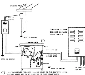
4.2 AC POWER DISTRIBUTION
Figure 4-1 shows a typical power system diagram. It is the
customer's responsibility to supply, install, and maintain the
following materials. (See Section 7 for reQuired circuit
breaker capacities.)
o The disconnect switch or circuit breaker for the input to the
transformer or motor generator set (Reference A, on Figure
4-1).
o The circuit breaker load center and circuit breakers for the
central system (Reference B). The rating of the main breaker
is determined by the total load.
o The circuit breaker load center and circuit breakers for peripheral eQuipment (Reference C).
o The main circuit breakers with a 24Vdc undervoltage release
coil for the circuit breaker load centers. The rating of the
circuit breaker is determined by the total load (Reference D).
o A 15A single pole circuit breaker for MG control unit
(Reference E) if an MG is utilized. The MG control unit is
connected to both the motor generator output and the utility power as indicated.
-t m ::;0 m o c: ::0 m 3: IT1 Z -t VI o c ~
•
I o o "TI G"> c: ::0 IT1 ~ I....
o»
CO) ::;0 » ~REFERENCE UTILITY POWER
A UTILITY POWER
1
DISCONNECT SWITCHOR CIRCUIT BREAKER
MG VOLTAGE RATING MUST MATCH UTILITY POWER
A I R ,-PHASE
:-0;;-;;]
CONDITIONER ISOLA1JON
EMERGENCY-OFF TRANSFORMER
ISOLATION
~---+;2-;---:-rlT.!.!!.L
T~ARNS ~
______ ,,", ____ • ___M~i')
: SINGLE PHASE(!)-.
MG 5~T
I
I II I
I 1
J
!
~ RELEASE COil CONTROL ~ RELEASE COil
(EMERGENCY-OFF) CIRCUIT BREAKER (EMERGENCY-OFF) BREAKER
Ii"
UNDERVOL TAGE:[r
MAINE~ENCY
f'C\
UNDERVOL TAGE AIN C I RCU IT(FOR TRANSFORMER OPER.)
m ~ m en m Z n
0(
,
o
""
""
«
II I
)
S
15
5 \
II
m~:~~OR
) ) )1,:)-1 ( U N I T
; It :2 0'" t PH I ( 2 ) '----t---+----I---I~+_--o---+----~
t
I ... - - - ___ JL ______________________ 1
• (2) (2)
,.... ... ...., ~...I.-...., ,._""-_ _ ,.... ... - - . ,....-'-~ ,.... ...
." ." t') ::on " ' 0
I
x~::0 C )10 m)lo ~
-
. ) 1 0-
•
::0.,.,
0 ' " a."•
n 0 0 0 ::O~ om~ :r: m )10 ,...
m m ::0 iii I'V'I
::0
'"
-
m »'"
'" ....n n
I
-
. " Z " " '0.,,""0 ."
I
:IOm:lV ::om::O•
c c ~.i o::o~'"
-
n - " ,0
-
"' o~ m.,,~r- 0
"'''''
",:r:.m c ",~m ""m.
e
•
0 " ' 0::0 0 : : 0 . _
"''-z en
L. - - - -'0- - - 0- - -_.J
L
EMERGENCY-OFF PUSHBUTTON AT ---1 t EX I T DOORS AS REQU I RED •- - - - . CONTROL WIRING
(n) NUMBER OF WIRES IN CONTROL WIRING
---·ALTERNATE POWER SOURCE
o The wiring and conduit from the circuit breaker load centers to each central system unit and each peripheral unit,
including connecting the input power to the disconnect
switches on each unit. Order and install sufficien~ wire for
a O.6m (2 ft) stubout length for each unit.
o The safety' ground from the circuit breaker load center and
each unit in the computer system to ground. This is the fifth
wire indicated in Sections 2 and 7 and it must be
green/yellow.
o The control wiring from the MG control unit to the MG, circuit
breaker load centers and emergency-off switches. See
Emergency Power-Off Wiring in this section.
o The ducts and/or cable trays for interconnecting logic cables if required by the electrical code or site layout.
o Any transformer(s) that may be required to provide an isolated power circuit for the system independent of other building power.
o The mounting for the circuit breaker load centers, isolating them from each other and from any contact with the building ground.
NOTES:
o Aluminum wire is not acceptable for this application.
o Certain peripherals are equipped with ac power cords (see Section 7).
o The 1SA circuit breaker must be connected to the utility as shown in Figure 4-1 (Reference E) to permit the air
conditioner to start UP automatically after a power outage.
When power is lost, the main circuit breaker in the peripheral circuit breaker load center must be manually reset to restore power to the devices it supplies. If the MG control unit took power from the peripheral circuit breaker load center, the air conditioning is not restored until the main breakers are
reset.
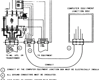
o All runs in metal conduit must be isolated for their entire
length from building ground. Insulated conduit material may
be required to meet this specification. Plastic bushings are
required to electrically isolate conduit from the computer units (see Figure 7-3 in Section 7).
It is also the customer's responsibility to install the following Honeywell-supplied items:
o The motor generator set and MG control unit.
o The ground braid from utility, UPS or MG to MMU location.
4.3 MOTOR GENERATOR SPECIFICATIONS
If you require a motor generator (MG) set, it should normally be shipped to your site one month prior to the arrival of your
system. The MG should be instaiied, wired and tested by your
electrician or contractor before the installation of the system.
The motor generator set must be selected in accordance with the
utility power provided at thes~teand with the system load.
taking into ~ccount line losses and future expansion. Refer to
the Installation Planning Drawings in Section 1. In some cases,
it may be necessary to change the motor wiring to match the
utility voltage available at the site. Instructions for doing
this will usually be found on the motor frame andlor in the
instruction manual shipped with the MG set. The MG usually
comes factory wired for 440-480 volts. but may be reconnected on site to accommodate 208-240V.
line losses must be considered if the load approaches the rating of the generator and the generator is remotely located.
4.4 UNINTERRUPTIBlE POWER SYSTEM
If your system availability criterion necessitates an
uninterruptible power system, your Honeywell representative can
assist in obtaining interface requirements. Figure 4-2
illustrates two UPS designs. With only storage batteries as
backup, the length of time the system could continue to operate
would be limited. From a practical viewpoint. it is suggested
that 15 minutes of battery holdup time be provided. With engine
generator backup, and with ioom air conditioning supported by
the UPS, the system will continue to operate regardless of the
length of time utility power is interrupted. Honeywell
Engineering can evaluate UPS design for your operation upon submission of complete specification of the UPS and its loads, via Request for Price Quote (RPQ).
4.5 50/60 HZ OPERATION
The central system units have jumper connections to select 50 or
60 Hz operation at the time of installation. Peripheral
processors and devices must be ordered for 50 Hz or 60 Hz
operation by model number. Honeywell does not supply a 50 Hz
motor generator.