2017 International Conference on Electronic and Information Technology (ICEIT 2017) ISBN: 978-1-60595-526-1
Design and Simulation of Double Closed-loop DC Motor Speed
Regulation System with Fuzzy PID Controller
Zi-wei LI
1and Cui-hua LUO
a,*College of Electrical and Information Engineering, Southwest Minzu University, Chengdu, Sichuan, 610041, China
a
*Corresponding author
Keywords: Fuzzy PID, DC motor control, Double closed-loop.
Abstract. This paper introduced the principle of one dual closed-loop DC motor speed control system with fuzzy PID controller. The algorithm could reduce the setting time and the over-shoot of the step response of the speed-current loop control system, with comparison of the traditional PID after simulation.
Introduction
The traditional PID was too difficult to adjust some controlled system with nonlinear, time-varying, and uncertainties, even arrived at the less satisfactory performance results, such as direct-current motor. In this paper, one double-loop PID controlled was presented to improve the performance of the object, by fuzzy adjuster. The method could coordinate all various parameters to achieve adaptability and flexibility. At the last parts, several sets of simulation were made to demonstrate its advantages with traditional PID controllers by simple loop and dual structures.
Dual Closed-loop DC Motor Speed Control Principle
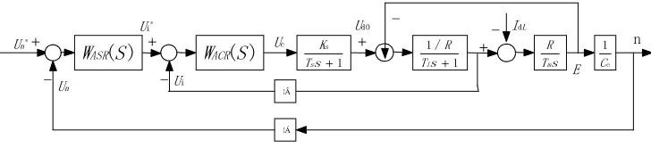
In order to eliminate the influence of the load’s disturbance in steady state, we usually add the speed’s feedback regulator basis on the open-loop control system and add the current cut-off negative feedback basis on the speed’s feedback to limit the impact of the pivot current.The dynamic structure of double closed-loop DC speed control system is shown in figure 1.
) (S
WACR TsKs+1
s 1
/ 1
+ s T
R
l Ts
R
m e
1 C
¦Â
¦Á
) (S WASR
*
n U +
-
--
-+ + + n
L Id
n
U Ui
*
i U
c U
0 d U
[image:1.612.124.488.533.616.2]E
Figure 1. The structure of double closed-loop DC speed control system.
where, WASR(S)is the transfer function of speed regulator, WACR(S) the transfer
Speed Regulator Principle
Feedback
is a process which can inhibit or even eliminate the impact of the disturbance
on the entire system effectively. The system is controlled by a deviation which is
generated by the comparison between the measured value and the given value. In order
to digitize the signal of speed, we generally use the encoder connected with the DC
motor which rotates to drive the encoder.
In order to achieve the floating speed regulation, there must be an integration loop
ahead of the load disturbance point, which can make the system maintain the constant
speed with floating. Because there is already an integration loop behind the load
disturbance point, the open-loop transfer function of the speed loop should have a total
of two integrations loop and should be designed as a typical type II system. The
saturation nonlinear of the speed regulator system will greatly reduce the over-shoot ,
therefore, the PI regulator is usually adopted in fact. The transfer function is:
s
τ
)
s
(τ
K
(S)
W
n n nASR
1
.(1)
where,
Knis the proportional coefficient of the speed regulator,
τ
nthe speed regulator
lead time constant of the speed regulator. The speed regulation system open-loop
transfer function is:
2
(
1)
( )
(
1)
n n nn e m n
K
α
Rτ
s
W s
τ β
C T s T
s
.(2)
The open-loop gain is:
n N
n e m
K
R
K
C T
. (3)
Taking into account equation (3), (2) becomes:
2 1 1 N n n n
K (
τs
)
W (s)
s (T
s
)
.
(4)
hT
. (5)
Refer to equation (5), the following equation can be deduced:
n
n
hT
. (6)
2 2
h
1
2
K
h T
.(7)
From (7), the following equation can be deduced:
2 2
1
2
N nh
K
h T
.(8)
Taking into account equations (6), (8), and (2) becomes:
(
1)
2
e m n
n
h
C T
K
h RT
. (9)
Current Regulator Principle
When the motor starts, stops or is in the blocked state, the current is larger than the
allowable current, so we introduce the current cut-off negative feedback. We connect a
small resistor R
sin series with the motor armature circuit, making the comparison with
the resulting current I
dand the critical cut-off current I
der, when Id is greater than I
der, the
I
dis added to the amplifier input, when the I
dis smaller than I
der, we should use the
microcontroller to cut off the current feedback [1].
The main role of current regulator is to follow, it should use type I system and PI
regulation, the transfer function is:
s
τ
)
s
(τ
K
(S)
W
i i iACR
1
. (10)
where,
Kiis the proportional coefficient of the current regulator,
τ
ithe forward time
constant of the current regulator, and the open-loop transfer function of the current loop
is:
s
opi
1
R
(
1)(
1)
i i
i l i
K (τ
s
)
K
W (S)
τ
s
T s
T
s
. (11)
Since
Ti>>
T i, select
τ
i=
Ti, use the adjuster zero to eliminate the large time
constant pole in the control object, so:
i i
( )
(
1)
(
1)
i I
opi
i
K
Ks R
K
W
s
s T
s
s T s
. (12)
In equation (12),
i s I l
K K
K
T R
. (13)
Under normal circumstances,
0.707,
K T
I i 0.5.
Then,
) ( 2 2 i i l S i S l
T
T
K
R
T
K
R
T
K
. (14)
Fuzzy Controller
Fuzzy Controller Principle
There are many vague concepts in human thinking, some concepts without connotation
and extension can only be described by fuzzy sets, which are expressed as
A
, others
have a clear connotation and denotation, they are called the general set or the classic set.
The function called the fuzzy characteristic function is the membership functions, it is
recorded as
μ
A
(x)
[2].
The size of the membership function reflects the degree of
membership of the element to the fuzzy set
A
.
consists of a database and a rule base, the database stores the membership values of the
fuzzy sets of all the output variables, the rule base is used to store the fuzzy control rules.
In order to get the fuzzy control quantity, inference engine is based on the amount of
fuzzy input and knowledge base to complete the fuzzy inference to solve the fuzzy
equation. The output clearness interface is to clarify the amount of output blur obtained
by the fuzzy decision and converts it to a precise amount.
Fuzzy Controller Design
[image:4.595.182.412.287.448.2]In fuzzy control, the general choice of ‘large, medium and small’ to describe the fuzzy
controller input and output value, plus positive, negative and zero state, there are seven
words: {negative big, negative middle, negative small, zero, positive small, positive
middle, positive big }. Its abbreviations are: {NB, NM, NS, O, PS, PM, PB}. Due to the
discourse domain of input and output is [-6,6], we can divide the discourse domain into
n files to get the input and output membership function[2].
The fuzzy subset
membership function is shown in figure 2.
Figure 2. Fuzzy subset membership function
For a DC motor speed control system, not only to consider the error given value and
the actual value, but also to consider the change rate error, so the system should meet
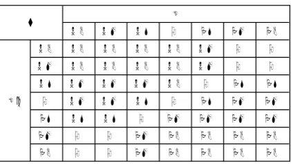
when the simultaneous input A and B, then output C. The corresponding statement is ‘if
A and B then C’, through this sentence to design fuzzy controller rules in table 1[3].
Table 1. Fuzzy controller rules
[image:4.595.193.404.557.676.2]1
s
s T
K
s 1
/ 1
s T
R
l Ts
R
m e
1 C
β
α
) (S WASR
*
n
U
-
- IdL n
n
U
i
U *
i
U
c
U
0 d
U
E
fuzzy controller fuzzy
[image:5.595.93.504.74.144.2]controller WACR(S)
Figure 3. The structure of dual closed-loop DC motor with fuzzy controller
Simulation Design and Results Data Analysis
[image:5.595.95.500.310.398.2]According to the relevant information, the DC motor parameters are as follows: rated
voltage is 220V, rated current is 136A, rated speed 1460r/s,
C =0.132V min/r
e
, allow
overload multiple
λ=1.5, thyristor amplification factor:
K =40S, armature circuit total
resistance:
R=0.5Ω, time constant:
T =0.03sl,
T =0.18sm, current feedback
coefficient:
β
=0.05V/A
, speed feedback coefficient
α
=0.007V min/r
, no static speed
requirements[1]. we can use MATLAB to simulate, the models and the waveform is as
figure 4, figuer 5 and figure 6.
Figure 4. Simulation mode of dual-loop DC motor speed control system
Figure 5. Simulation model of dual closed-loop DC motor based on fuzzy controller
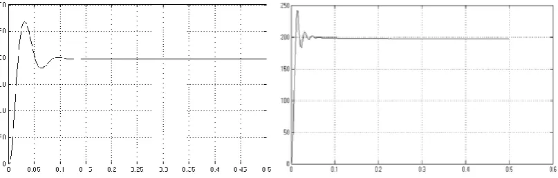
(a) traditional PID controller (b) fuzzy PID controller
[image:5.595.96.498.430.540.2] [image:5.595.96.500.574.703.2]From the waveform of the traditional PID controller and the fuzzy PID controller, we
can infer that the fuzzy PID control could reduce the setting time and the over-shoot of
the step response and it can make the system reach the stability faster. Therefore, we can
conclude that the fuzzy PID controller can improve the dynamic and stability of the
speed control system. As a whole, the fuzzy PID controllers have better suitability. It
has more obvious advantages than the traditional PID controller.
Conclusion
In this paper, the fuzzy algorithm was combined with double closed-loop DC motor
speed control system. After simulation, the result of the fuzzy PID controller was
compared with the result of the traditional PID controller. The results show that the
fuzzy controller has good stability, dynamic and robustness. It also has good
adaptability and flexibility to parameters. The fuzzy controllers have many advantages.
Therefore, it has been mainly applied in aerospace, advanced electronic equipment,
medical equipment, chemical and other advanced technology.
Acknowledgement
This paper was completed with the assistance of my friends. Cuihua LUO is my
instructor; she gave me the idea of the paper and helped me to correct the format of the
paper. My seniors helped me find the problem in the article and told me how to polish
the article, and my friend helped me type the paper. Thanks to the conference for
accepting my paper and giving me suggestions for revision. Thanks to the authors of my
reference, they gave me great inspiration.
References
[1] Yi RUAN, Boshi CHEN, Control Systems of Electric Drives—Motion Control
Systems, in, Machinery Industry Press, 2009.8, PP79-88.
[2] Haisheng YU, etc, Microcomputer control technology, Tsinghua University Press,
2017. PP183-184, PP188-190.