2017 3rd International Conference on Electronic Information Technology and Intellectualization (ICEITI 2017) ISBN: 978-1-60595-512-4
A Method of Calibrating ATE While Testing
Houping Zhou, Xuanmian Li and Yong Hu
ABSTRACT
A method of calibrating the integrated circuit ATE (Automatic Test Equipment) by synchronizing and measuring the signal on the DUT (Device Under Test) side while test is presented. This method connects the measuring instrument[1] to the pin of the DUT. Then the calibration software from the control computer receives the indication from the measuring instrument and the measurand[1] from the ATE. At last, the specifications of the ATE are calibrated via analyzing data from the measuring instrument and compare with the data from the ATE.
INTRODUCTION
The most popular and widely used calibration methods for the ATE are sub-calibration method, calibration board method, MAP calibration method and material measure method[2]. The principle is to execute a dedicated calibration software on the ATE system to drive or measure the signal what user configured and calibrated this signal by the measuring instrument directly except the material measure method, as shown in figure 1.
However, the calibration methods above can not represent the accuracy of the test; they also can not demonstrate the actual performance of the ATE. First, the interfaces of measurement on the calibration board or trace board are not the same as the DUT socket, so are the measurements. Meanwhile, they're also impossible to program and debug a calibration software on each ATE system with varies of operation system and hardware platform.
This paper represents the new method for calibrating ATE on the DUT side while test. The measuring instruments are connected to each pin of the DUT appropriately; they measure voltage, current and the time on the same _________________________
position. When the test program is executed, the expected values like drive voltage, current and rising/falling edge were known by the configuration though the program. As soon as they are compared and analyzed with the indication read from the measuring instrument, this parameter is calibrated. By this method, the calibration result is more reliable because the calibration interface is the same as the test interface. Meanwhile, the redundant channels were calibrated at the same time because the test vectors are executed in parallel. At last, a specific calibration program on the ATE is unnecessary because the method introduced in this paper calibrates the ATE by a general test program and it has nothing to do with its hardware and operation system.
Dedicated Calibration
Program
ATE system Driver Unit
Measurement Unit
Measuring Instrument
Measuring Instrument
[image:2.612.161.425.243.375.2]
Figure 1. Basic principle of calibrating ATE.
PRINCIPLE
Calibration Method
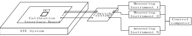
ATE System Calibration Interface Board
DUT
Switch system
Measuring Instrument 1
Measuring Instrument 2
measuring Instrument N
Control computer
Figure 2. The hardware connection diagram.
[image:2.612.132.463.493.556.2]control computer. Finally, the indications of the parameters in the ATE are calculated though the data and waveform, and the calibration is completed when comparing the indication and the configuration from the test program.
Synchronization Method
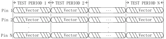
Synchronization method is the most challengeable part in this calibration method. However, it's possible to recognize the ATE's behavior though the data via continuous measurement by measuring instrument. Because the primary test procedure is to test while execute a certain vector repetitively. The waveform for a test procedure was shown in Figure 3.
As soon as the test period is known from the test program configuration, a timer can be used in the calibration software to recognize the meaning of the data. For instance, the test period is configured as 1MHz, then test period is 1μs. The data in 100μs~101μs is measured in the NO.101 test period. If the pin is a DPS pin and the setting voltage in the NO.101 period of the test program is 3.3V, the average voltage indication in 100μs~101μs is 3.3001V, then the error is -0.001V and the 3.3V voltage of the DPS was calibrated.
Vector Vector ... Vector
Vector Vector ... Vector
Vector Vector ... Vector
. . .
. . .
Pin 1
Pin 2
Pin N
[image:3.612.134.471.370.450.2]TEST PERIOD 1 TEST PERIOD 2 TEST PERIOD N
Figure 3. The waveform on each pin.
DC COMPONENT CALIBRATION
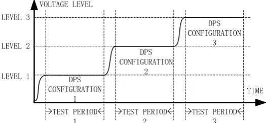
The DC components in the ATE consist of DPS and PMU mainly. The DPS (Device Power Supplies) supply the power to the DUT as a drive component. The PMU, as a precious measurement component, measure the DC specifications of the DUT. Basically, the test program configures several typical power conditions to test the specifications, the waveform on the DUT's power pin changes as shown in figure 4.
uncertainty and compare with drive voltage configuration in the test program, the 3 voltage measurand driven by DPS have been calibrated.
After the PMU measured the specifications, the measurands can be found in the test log file or the test report. At the same period, the indication was stored and sent to the control computer too. When the measurands from PMU and indications from the measuring instrument were paired and calculated, the calibration for the PMU was done.
DPS CONFIGURATION
1
DPS CONFIGURATION
2
DPS CONFIGURATION
3 VOLTAGE LEVEL
TIME
TEST PERIOD 1
TEST PERIOD 2
TEST PERIOD 3 LEVEL 1
[image:4.612.171.434.215.337.2]LEVEL 2 LEVEL 3
Figure 4. Typical Waveform on the DPS pin.
AC COMPONENT CALIBRATION
Time Voltage
Time LOGIC 0
LOGIC 1
Minimum Voltage OUTPUT
INPUT
Figure 5. The searching test diagram.
TIMING COMPONENT CALIBRATION
Timing component test the rising / falling time and delay of edges. The rising / falling time and delay appear in the single vector, and it's a average value of this characteristic in the setting vector. When calibrate this component, the measuring instrument should be the time measuring instrument and line impedance needs to be matched. The procedure of calibration is similar with the PMU, because both PMU and timing component are measurement units, the measurands measured by ATE need to be export from the log file or test report and pair it with the indications from measuring instrument to complete the calibration procedure.
CONLUSIONS
A method of calibrating ATE while test is introduced in this paper. It solves the issues of calibrating ATE. First, this method doesn't need to program on the target ATE system. Meanwhile, the cost is extremely high if stop the system from test to program and debug the calibration software. After that, it's impossible to be compatible with all ATE systems based on different hardware and software platform. Second, this method represents a more reliable calibration result on the DUT side while test, because the test position and calibration position are the same.
On the other hand, this method also needs complex circuits and other supporting systems like switch system and measuring instruments. After that, the efficiency is still not good enough for calibrating the measurement units like PMU and timing unit, because the measurand in the ATE need to be find and paired with the indication from measuring instrument.
REFERENCES
1. State Administration of Quality Supervision, Inspection and Quarantine. General Terms in Metrology and Their Definitions.2012.