2017 2nd International Conference on Computer, Mechatronics and Electronic Engineering (CMEE 2017) ISBN: 978-1-60595-532-2
Dynamics Modeling and Optimization of Beam in Flip Chip of LED
Based on Rayleigh Method
Xue-li LI
1, Lu-fan ZHANG
2,3,*, Qin-liang LI
2, Su-xiang ZHANG
1and Hu LI
3 1School of Mechanical and Electronic Engineering, Zhongyuan University of Technology, Zhengzhou 450007, China
2
School of Mechanical and Electrical Engineering, Henan University of Technology, Zhengzhou 450001, China
3
Weihua Group Co., Ltd., Changyuan 453400, China
*Corresponding author
Keywords: Beam, Rayleigh method, Dynamical modeling, Optimization.
Abstract. It is very important for superior performance beam in flip chip of LED to realize its work efficiently and accurate positioning. To obtain the superior performance of beam, its dynamic mode is built and carried out by Rayleigh method, and it is explored to find out the change trend of the natural frequency and deflection of the beam with its structural parameters. Based on the dynamic modeling of beam, optimization model of beam is built and its optimization solution is obtained by genetic algorithm. The results provide a theoretical basis on the further design and dynamic analysis of flip chip of LED.
Introduction
LED chip manufacturing has been important position in the national production, its domestic and international technology development has got widespread attention. With the rapid development of microelectronics technology and the need of high-performance integrated circuits, the development trend of the chip packaging technology is toward high I/O density, short interconnect, good heat dissipation, high productivity and smaller size. Flip chip packaging is an advanced chip interconnection technology, and it has become one of the most competitive technologies in modern electronic packaging because of its high density, high performance, interconnection process of self-alignment and light and short features [1-3], moreover, it has become the main development of high-density packaging technology widely using in high-frequency communications, high-performance computers and smart phones, tablet personal computers, digital cameras and other consumer electronics products [4]. Under the condition of encapsulating highly integrated and internal connection higher performance, the electrical connection of Flip-chip has become a trend from the lead to the solder ball, and the trend is also fully reflected in other applications except encapsulation such as printed circuit boards and chips [5].
packaging device and so on. Many scholars have studied on the LED flip machine movement structure of the simplified and optimized analysis, parameter optimization design and other aspects of research [10, 11]. To further improve the precision and stability of LED flip chip for chip packaging equipment, this paper mainly studies the dynamics modeling and optimization of the beam in Flip chip of LED. The dynamic model of beam is established by Rayleigh method, and the genetic algorithm is used to optimize the study. The natural frequency and the minimum disturbance of the beam of the LED flip machine are obtained, so as to avoid resonance and reduce the damage to the beam. The research content is important machine design, dynamic analysis, improving stability and extending the service life of the LED flip chip system.
The Beam of Flip Chip of LED
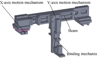
Flip chip of LED is a high-speed precision chip packaging equipment integrating mechanical, electrical and control, which includes the binding mechanism, XY movement platform and other modules. The beam of flip chip holding the binding mechanism and the XY movement platform, as shown in Fig. 1. XY movement platform consists of X-axis motion mechanism and Y-axis motion mechanism, and it is mainly responsible for the LED chip from the wafer to LED bracket. X-axis motion mechanism as a key mechanism of XY movement platform, its structural stiffness has an important role for the precise positioning in flip chip of LED. With the help of the XY movement platform, the binding mechanism is used to complete sucking the chip, fluid dispensing and the precise positioning between chip and the holder.
[image:2.612.90.278.376.495.2]
Figure 1. Structure of beam in flip chip of LED. Figure 2. Theoretical model of beam.
Dynamic Modeling of Beam
The beam dynamic mode can be obtained to find the natural frequency of the beam by the Rayleigh method, and then the resonance can be avoided when the vibration force is applied in the system, and the damage to the beam can be reduced and the service life is prolonged.
The beam is simplified as a model, as shown in Fig. 2, and the mass per unit length of the simply supported beam is ρ, the mass of the beam is m, the elastic modulus is E, the moment of inertia is I=bh3/12, the length is l. The deflection of simply supported beam at the cross-section x can be obtained from the material mechanics [12].
Assuming that the deflection curve y (x, t) of the beam is a static deflection curve with central force acting on the center, then:
( )
x ll x l
x y t x
y , c 3 4 0 0.5
3
≤ ≤
−
There, yc is a deflection of the midpoint of the beam, and is a function of time in the vibration:
( )
t c c yy = (2)
Setting:
( )
3 4 3 − = l x l x x
f (3)
So: y
( )
x,t =yc( ) ( )
t f x (4)There, f(x) is the displacement of each point of the beam with unit displacement. The equivalent mass of the beam can be obtained as follows [13]:
l dx l x l x
me ρ l ρ
35 17 4 3 2 2 5 . 0 0 3 = −
=
∫
(5)There, ρ is the mass per unit length of the beam.
The beam will be simplified as a spring quality system, and the stiffness of the simply supported beam in the central by the concentrated force can be obtained as follows:
3
48 l
EI
k= (6)
The circular frequency of the beam can be obtained as follows:
3 35 17 48 l l m EI m m k e n + = + = ρ
ϖ (7)
The natural frequency of the beam can be obtained as follows:
3 35 17 48 2 1 2 1 2 l l m EI m m k f e n + = + = = ρ π π π ϖ (8)
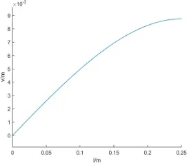
The deflection of the beam can be obtained as follows:
(
l x)
x lEI mgx 5 . 0 0 4 3 48 2
2− ≤ ≤
=
υ (9)
The Change Trends of Deflection and Frequency
found that the change trend of deflection and natural frequency are significant on the parameters of the beam. Therefore, it is important for avoiding resonance and obtaining high performance to obtain the highest first order natural frequency and the minimum disturbance of the beam by carrying out the parameters optimization of the beam.
Figure 3. The change trend of the deflection with the length l of the beam.
[image:4.612.320.480.290.405.2]
Figure 4. The change trend of the natural frequency. Figure 5. The change trend of the deflection.
Optimization Analysis
In order to obtain high performance beam, the optimization model of the beam can be established to carry out the beam optimization study as follows:
The maximization of the first order natural frequency and the minimization of the deflection are the main objectives of realizing the high performance beam. In this paper, the two optimization goals are transformed into an optimization target to optimize the solution.
An optimization model is built as follows:
(
2 2)
34 3 48 35
17 48 2
1
x l EI mgx
l l m
EI f
F − −
+ =
− =
ρ π
ν (10)
There, 0.01≤b≤0.1, 0.01≤h≤0.1.
Genetic algorithm follows the evolution of the biological world "natural selection, survival of the fittest" evolution rule based on the study of biological genetic research.
[image:4.612.132.292.293.406.2]framework of complex system optimization problem. On the basis of Hertz theory, it is calculated by genetic algorithm. F, as the objective function, the binary code is selected, and genetic algorithm related parameters is shown in Table 1.
Table 1. Related parameters of genetic algorithm.
Population Maximum
genetic iteration Individual
Generation
gap
Crossover
probability
Mutation
probability
40 50 40 0.95 0.7 0.01
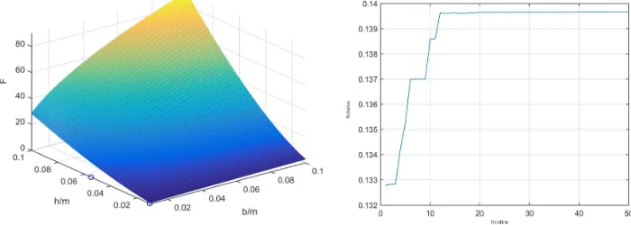
[image:5.612.127.477.304.429.2]In the process of optimization, the objective function changes with the initial width and height of the beam. As the initial width and height increase, their corresponding objective function value increases rapidly. The disturbance has little effect on the objective function because of the small value. The optimal solution of the objective function is centered on the top of the graph, as shown in Fig. 6. In the population evolution process of 50 generations, the target solution is converged when it iterates to 12 times, which also shows the advantage of using the fast convergence of genetic algorithm, as shown in Fig. 7. The optimal solution is obtained by optimization: b = h = 0.1.
Figure 6. The optimal solution for each generation. Figure 7. Iteration of optimization.
Summary
In this paper, the beam of the LED flip machine was studied, and its dynamic model was built by the Rayleigh method. Based on the dynamic model, the change trend of the deflection and the natural frequency with the parameters of the beam could be obtained. The beam decreased rapidly with the increase of the width and the height, and the natural frequency of the beam increased with the width. Moreover, the optimization model was established, and the optimal solution was performed by genetic algorithm. The optimal configuration of the beam structure was obtained: b = h = 0.1. The results provide a theoretical basis on the further design and dynamic analysis of flip chip of LED.
Acknowledgement
Reference
[1] L. Ye, L. Tang, Z. Liu, Summary of Flip Chip Bonding Technology and Equipment, J. Equipment for Electronic Products Manufacturing. (237) 2014 1-5.
[2] S. Gao, The Development and Challenge of the Advanced Packaging Technology, J. China Integrated Circuit. (89) 2006 48-53.
[3] T. He, The Future Trend of Advanced Packaging Technology, J. Equipment for Electronic Products Manufacturing. (124) 2005 5-8.
[4] W. Huang, H. Zhou, Advanced Electronic Encapsulating Technology and Materials, J. Fine and Specialty Chemicals. 14 (16) 2006 1-5.
[5] X. Li, Flip Chip will be a New Method of Packaging Technology, J. Electronics & Packaging. 4 (4) 2004 18-19.
[6] Z. Liu, Research on key issues of high power LED packaging design and manufacturing. PhD Thesis. Wuhan: Huazhong University of Science and Technology, 2010.
[7] China semiconductor industry association China electronic information industry development research institute. Chinese semiconductor industry development report. Xi’an, 2013.
[8] Electronics Manufacturing and Packaging Technology Branch of China Electronics Association and Electronic Packaging Technology Series Editorial Board. Electronic Packaging Technology Equipment. Beijing: Chemical Industry Press, 2012.
[9] Q. Wu, S. Chen, S. Dong, Optimization of parameters structural design of
lightweight reflector. Optics and Precision Engineering. 11 (5) 2003 466-471.
[10] Z. He, G. Lin, Research on Optimal Design of Complex Mechanical Systems. Mechan Ical Sc Ience and Technology. 25 (2) 2006 158-162.
[11] X. Liang, H. Wang. Structure optimization design based on finite element method-principle and engineering application. Beijing: Tsinghua University Press, 2010.
[12] L. Zhang. Mechanics of materials. Beijing: China Agriculture Press, 2003.
[13] W. Wang, Y. Lai, T. Miao, Vibration mechanics and engineering applications. Zhengzhou: Zhengzhou University Press, 2008.