2017 2nd International Conference on Computer, Mechatronics and Electronic Engineering (CMEE 2017) ISBN: 978-1-60595-532-2
The Precise Detection Techniques in Optical Lenses Alignment
Deng-yu ZHOU, Xin YE, Zhi-jing ZHANG
*and Zi-fu WANG
Beijing Institute of Technology, 5 South Zhongguancun Street, Haidian District, Beijing, China *Corresponding author
Keywords: Precise detection, Mechanical axis, Optical axis, Lenses alignment.
Abstract. For the high-precision optical lens alignment, the coaxiality of the mechanical axes of the optical components and the lens barrel cannot guarantee good optical performance. As the centering error’s existence of the optical lens, the optical axis of the lens is supposed to be detected to ensure the centering error in required range. The precise detection techniques of mechanical axis and optical axis of the optical component are put forward. Then, the mechanical axis and optical axis integrated precision detection system (MOADS for short) is proposed. Based on the MOADS, the alignment process of optical lenses is put forward.
Introduction
With the rapid development of optical technology, optical lenses are more and more widely used in aerospace, machine vision, photography and other fields [1, 2]. The alignment accuracy of optical components affects the optical performance to a great extent. In the alignment process of ordinary optical lenses, the mechanical axis of the optical lens or spacer should coincide with the mechanical axis of the lens barrel, so that the lens and spacer can be placed in the lens barrel accurately. In addition, in the alignment process of precision optical lenses, the optical performance of the lenses cannot be guaranteed completely only by the coinciding of the mechanical axes. There is a gap between the optical components and the lens barrel, it is also necessary for the lens to adjust its position so that the centering error of the optical axis of the lens can be ensured in required accuracy range. Therefore, the precise detection techniques of mechanical axis and optical axis of the optical component are put forward, which make it easier in the precise assembly process of precision optical lenses. The mechanical axis and optical axis integrated precision detection system is proposed, and based on that the alignment process of optical lenses is put forward.
The Mechanical Axis Detection Technique
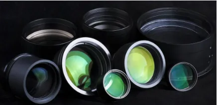
[image:1.612.198.416.607.713.2]To begin with, the basic components of optical lenses need to be introduced. An optical lens is the basic unit of an optical lenses, consisting of two curved surfaces filled with a transparent medium (such as glass). A spacer is usually an aluminum ring that puts between two lenses in the optical lenses. For convenience, the optical lens and the spacer are called optical components. The lens barrel supports lenses and spacers. There are several positioning ladders in the inner of the lens barrel.
In our early work, Tang and Zhang proposed the coaxial alignment detection method for micro assembly (MSCA for short) whose detection accuracy can be up to several microns [3, 4]. This method is used to fit and align the mechanical axis of the optical lens, the spacer, and the lens barrel in the mechanical axis detection technique.
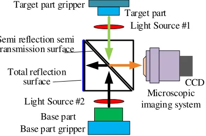
An industrial CCD camera and a cube prism is used to establish the mechanical axis detection system which is shown in Figure 1. There is a semi reflection semi transmission surface in the cube prism to make both the target parts and the base part can be captured simultaneously in the same image plane. For the optical component as the target part and the lens barrel as the base part, the edges of their images both are circular. After obtaining the edge images of the target part and the base part, the edge recognition and the circle fitting are carried out, and the center of the circle can be used to describe the mechanical axis of the parts. By calculating the deviation of two center points, the position and deviation of the mechanical axis of the optical parts and the lens barrel can be obtained, and the detection of the mechanical axis is completed.
Base part gripper Target part gripper
Target part
CCD
Base part
Microscopic imaging system Light Source #1 Semi reflection semi
transmission surface
Total reflection surface
[image:2.612.206.417.251.391.2]Light Source #2
Figure 2. The mechanical axis detection system.
As shown in Figure 2, the microscopic imaging system mainly includes the CCD camera, camera lens, light source, optical alignment module, image processing and calculation compensation software and so on. Among them, the core components of the microscopic imaging system are the camera lens and the CCD camera, which directly affect the image quality of target part and base part and the image processing calculation error. As a result, the detection precision of the whole system would be affected by them.
The Optical Axis Detection Technique
Spherical surface of measured lens
The spherical
center The reticle draws a circle. Lens
gripper Light Souce
Reticle
Autocollimator
Focusing Objective
Lens CCD camera
θ
C O The image on
CCD
Zoom in
(x, y)
Rotary table
Rotary table
Figure 3. Theoptical axis detection technique.
This detection technique can measure the coordinates of curvature center points of each surface of an optical lens [8, 9]. Once the curvature center points of the upper and lower surfaces are both obtained, the optical axis of this optical lens is determined.
In the detection process, the rotating axis of the air bearing rotary table is used as the reference axis. When we measure the upper surface of an optical lens, the light of reticle emitted from the autocollimator and then the reticle is converged to the focal plane of the measuring head which includes the autocollimator and the focusing objective lens. With the moving of the measuring head, the reticle can also be converged to the focal plane of the measured lens. The reticle reflects back to the CCD camera to be recorded on the image plane. Thus, the image of the reticle center can be regarded as the curvature center point of the upper surface (denoted by Cu). Usually, the center point Cu deviates from the reference axis. When the rotary table is driving the lens to rotate in a circle, the point Cu will also rotate in a circle to form a complete circle, and the radius of the circle can represent the deviation of the point Cu of the upper surface from the reference axis. Similarly, the curvature center point of the lower surface (denoted by Cl) can be obtained. Thus, the optical axis through these two points (Cu and Cl) can be determined. To sum up, this is the whole process of the optical axis detection.
The Mechanical Axis and Optical Axis Integrated Precision Detection System
Precision 2D platform Gripper Gripper CCD Camera Optical components Light Source #1
Light Source #2
Lens barrel
Air bearing rotary table
The base platform Light
source
The optical axis detection system
The mechanical axis detection system
Linear moving stage Z axis moving
stage
α&β
adjustment stages Camera lens Reticle Linear moving stage Prism Auto-collimator CCD
Figure 4. The mechanical axis and optical axis integrated precision detection system.
The Alignment Process of Optical Lenses
Based on the MOADS, the alignment process for precise optical lenses alignment is proposed. There are mainly 7 steps in the alignment flow chart shown in Figure 5.
Start
#1 Place the lens barrel
#2 Grip the optical components
#3 The mechanical axis detection of optical
components
#4 The optical components are adjusted and put into the
lens barrel
End #5 The optical axis
detection of optical lens
#6 The optical lense is adjusted coaxially
#7 All optical components are aligned coaxially
Figure 5. Alignment flow chart of optical lenses based on integrated detection system.
Step #1: The lens barrel should be placed coaxially with the reference axis (the rotating axis of the air bearing rotary table).
Step #2: The optical components are gripped and sent to be detected. Step #3: The optical components complete the mechanical axis detection.
Step #4: The optical components are adjusted to ensure their mechanical axes to be coaxial and then sent into the lens barrel by precision moving stages.
Step #5: The optical lens completes the optical axis detection.
for optical lenses. The MOADS is first used in the coaxial alignment of optical components, which plays an important role in the automatization of precision optical lenses alignment.
Acknowledgement
This work was financially supported by the National Natural Science Foundation of China (51575052).
References
[1] Lo Y C, Huang K T, Lee X H, et al. Optical design of a Butterfly lens for a street light based on a double-cluster LED[J]. Microelectronics Reliability, 2012, 52(5):889-893.
[2] Lee H S, Jeon W T, Kim S W. Development of Plastic Lenses for High-Resolution Phone Camera by Injection-Compression Molding [J]. Transactions of the Korean Society of Mechanical Engineers A, 2013, 37(1):39-46.
[3] Zhang Z, Zhang X, Ye X, et al. Micro-assembly precise coaxial alignment methodology based on surface roughness and reflectiveness matching[J]. Assembly Automation, 2014, 34(2):141-150.
[4] Ye X, Gao J, Zhang Z J. A Microassembly System with Coaxial Alignment Function [J]. Applied Mechanics & Materials, 2014, 487:678-681.
[5] Chatterjee A S, Kumar Y P. Measurement of centering error of a lens with cyclic optical configuration [J]. Optical Engineering, 2010, 49(4):258-258.
[6] Huang K C, Chang C L, Wu W H. Novel Image Polarization Method for Measurement of Lens Decentration [J]. IEEE Transactions on Instrumentation & Measurement, 2011, 60(5):1845-1853.
[7] Langehanenberg A P, Dumitrescu E, Heinisch J, et al. Automated measurement of centering errors and relative surface distances for the optimized assembly of micro-optics [J]. Proceedings of SPIE - The International Society for Optical Engineering, 2011, 7926(1):225-229.
[8] Heinisch J. Measurement of centering errors, automated adjustment and mounting of lenses [J]. Photonics Spectra, 2010.