Systems Reference Library
Autotest fo:r IBM
1401/1460
with IBM
1311:
Specifications and Operating Procedures
Program Number 1401-AT-081 (8K) 1401-AT -082 (16K)
This publication describes the specifications
and operating procedures for the IBM
1401/1311 Autotest 8K and the 1401/1311 Autotest 16K programs. Included are
sec-tions that define the control cards required, specify the arrangement of cards in the test deck, specify the autopatch card format and autopatching procedures, and describe the operating procedures for testing 1401/1311 Autocoder object programs.
Third Edition! June 1966
This is a reprint of C24-3195-1 incorporating changes released in the following Technioal Newsletter:
Form No.
N24-0272
Pages Affected
1, 8, 15, 16, 16.1, 16.2, 17, 18, 18.1, 18.2, 21, 22, 23, 25, and 26
October 15, 1964
Requests for copies of IBM publications should be made to your IBM representative or to the IBM branch office serving your locality.
Contents
Specifications "... 5
Machine Requirements ... .... ... ... ... 5
Autotest Specifications ... 6
Autotest Standard Features ... 6
Identification Card (IDC) ... 7
Console Status Card ... ... ... 7
Program Control Card (pcc) ... 7
Autotest Optional Features ... 8
Atltopatch Feature ... 21
80/80 Listing of Output Cards ... 26
Operating Procedures ... "... 27
PrograIll Deck Description ... ... ... 27
Autotest Setup Instructions ... 27
System Preparation ... ... 28
Autopatch Error Messages ... ... ... 30
Halts and Messages During Disk Utility Programs ... 30
Restarts ... , ... ,.. ... ... ... ... ... ... ... ... .... 34
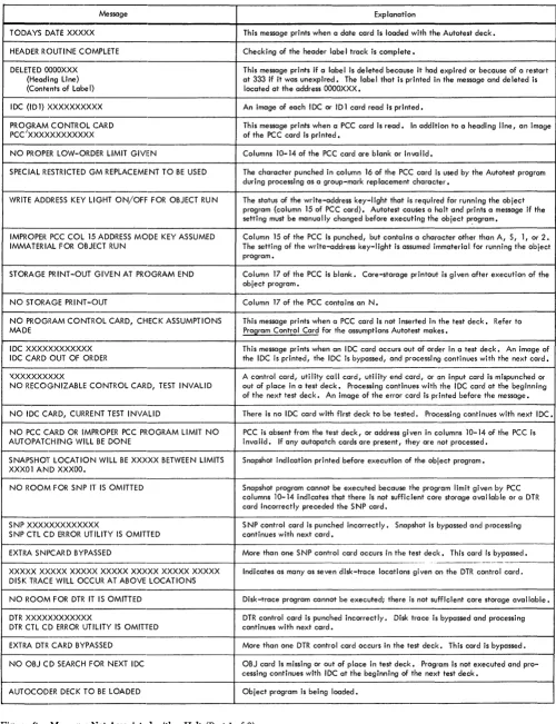
Autotest Halts and/or Messages ... 34
Autotest, a testing program for the IBM 1401 and 1460
Data Processing Systems, controls the use of utility programs to provide complete documentation for pro-gram evaXuation. It is useful for remote testing because it provides the programmer with an opportunity to pre-plan his test run with a minimum of operator in-tervention.
For a better understanding of the IBM 1401/1311
Disk Utility Programs used in Autotest, the reader should review the Systems B.eference Library (SRL) publications, Disk Utility Programs for IBM 1401/1311:
Specifications, Form C24-1484 and Disk Utility Pro-grams for IBM 1401/1311: Operating Procedures, Form
C24-3105.
There are two versions of the Autotest program available to the user, BK and 16K, depending on the
minimum size of the object machine used. Both ver-sions perform exactly the same functions and are de-signed so the core-storage area occupied by Autotest during the running of the object program occurs in the upper core-storage positions of the object machine
(BK or 10K) used. With the exception of some
core-storage considerations, the specifications and operating procedures for the two versions of Autotest are identi-cal. Where differences in the versions occur in this publication, the address for 16K Autotest appears first, without brackets, and the address for BK Autotest
fol-lows, included within brackets. Example: 15909
[7909].
The Autotel)t program:
• Clears core storage before loading each object pro-gram.
• Loads the object program. • Executes the object program.
Also, Autotest provides the following program fea-tures, which may be selected by the user.
1. Clear Disk Storage - Selected areas of disk storage can be cleared before or after execution of the object program.
2. Disk Record Load - Provides for the creation of disk :records from card input prior to the test of each individual program.
3. Print Disk - Data from selected areas of disk stor-age can be printed before or after execution of the object program.
Specifications
4. Disk-Label Program - Performs all necessary
maintenance operations on the label track of a disk pack.
5. Tape-File Generator - Provides for the creation of tape files prior to the test of each individual pro-gram.
6. Tape-to-Printer - Prints fixed- or variable-length, blocked or unblocked tape records.
7. Snapshot - Data from a selected area of core stor-age can be printed at specified times during the execution of the object program.
B. Disk Trace - Data that is read from, or written on, the disk during execution of the object program is traced and printed with the control field of the read or write instruction.
9. Core-Storage Printout - The contents of core stor-age can be printed at the end-of-job or when a hang-up condition occurs.
10. Autopatch - Allows the programmer to correct the object program without reassembling or computing 3-position machine addresses. Patch instructions can have indexed operands.
11. BO/BO List - An BO/BO list of all punched-card input and output can be obtained at the end of the complete test session.
Any number of these optional features can be used when testing an object pr<?gram.
The IBM 1401/1311 Autotest program requires that
the assembled program be in the same format as the condensed Autocoder card output.
Machine Requirements
The Autotest program can test programs written for all
IBM 1401/1460 systems. The machine used to test the
object programs must have the following configura-tion.
IBM 1401 Systems:
16,000 [8,000] positions of core storage An IBM 1311 Disk Storage Drive An IBM Disk Pack
An IBM 1402 Card Read-Punch
An IBM 1403 Printer, Model 2, or an IBM 1404 Printer Advanced Programming feature
High-Low-Equal-Compare feature
IBM 1460 Systems:
16,000 [8,000] positions of core storage An IBM 1311 Disk Storage Drive An IBM Disk Pack
An IBM 1402 Card Read-Punch An IBM 1403 Printer, Model 2 or 3
Indexing-and-Store-Address-Register feature
Autotest Specifications
Program Requirements
l. If control cards occur after the last data card in a
test deck, any last-card test must be changed to a
BRANCH IF CHARACTER EQUAL instruction. This can
be done with a replace-type autopatch card. (See
Autopatch Feature.) The last-card indication char-acter is punched in the last data card of the program to be tested. If the program does not use cards as input, this Autotest requirement can be ignored. 2. A snapshot routine can occur at any four-or-more
character instruction whose operands are not ad-dress-modified. It must not be a chained instruction. When it encounters the first snapshot, autotest automatically stores this instruction and then re-places it with an unconditional branch to the snap-shot routine. After snapsnap-shot is executed, the original instruction is executed and the program continues. Additional snapshots are accomplished by using autopatch cards to cause a branch to the snapshot routine located at 14907 [6907].
3. The segment-mark special character (0-7-8) should not be used in the object program if autopatch is to be used. Autopatch uses this special character internally as a group-mark with a word-mark re-placement character when loading the object pro-gram into disk storage. If the segment-mark special character (0-7-8) must be used, the programmer has the option of supplying another replacement character to the Autotest program. It is punched in the program control card. If this other character is specified, it must be excluded from the object pro-gram.
4. To decrease the time required for testing, the final halt (if a four-or-more character instruction) should be changed to an unconditional branch (not a haIt and branch) to an Autotest linkage routine. This can be done by using autopatch. If a final halt in the user's program is less than a 4-character instruction, the console operator must, after the program reaches this end-of-job haIt, manually adjust the console to branch to the linkage routine. The address of the Autotest linkage routine is 15909 (101) [7909 (IOZ)].
5. Object programs using the punch-feed-read special feature cannot be tested by Autotest.
6. If the disk-trace program that does not require a tape drive is used, disk read or write instructions located in positions 200-332 cannot be traced and/or any data read or written by disk instructions, and located in positions 200-332, cannot be displayed.
Autotest Standard Features
For every object program to be tested, Autotest auto-matically generates instructions to clear core storage, load the object program, and execute the object pro-gram. If the programmer desires, it also prints the contents of core storage after execution or when the machine stops because the program cannot be exe-cuted.
Clear Core Storage and Load Routine
Because Autotest automatically clears core storage and then loads the object program, the programmer should remove the loader (clear core storage and load routine) from the deck produced by the Autocoder processor. However, if these cards are not removed, Autotest automatically bypasses them.
After loading, Autotest executes the object program.
Core-Storage Printout
Autotest prints the contents of core storage at the conclusion of the object program unless the program-mer specifies otherwise on the program control card. The last instruction in the program to be tested branches to the Autotest linkage routine, which tests whether or not the core-storage printout program is to be executed. If it is to be executed, the routine loads the core-storage printout program from disk to core storage, and executes it immediately after loading.
The programmer can also specify that the contents of core storage are to be printed if the object pro-gram hangs up. After the machine halts, the operator can make the proper adjustments on the console to give control to the Autotest linkage routine in core storage. This routine loads the core-storage printout program from disk storage into core storage and exe-cutes it. If the Autotest linkage routine is destroyed by execution of the object program, a restart deck that reestablishes linkage is supplied by IBM.
UNPRINTABLE SUBSTITUTION
CHARACTERS CHARACTERS
( (12-5-8) $ (11-3-8)
<: (12-6-8) * ( 11-4-8)
:t:
(12-7-8) D ( 12-4-8)) (11-5-8) @ (4-8)
; (11-6-8) y (0-8)
fj, (11-7-8) /I (3-8)
. y (0-5-8) V (0-5)
~~ (0-7-8) / (0-1)
»
(6-8) X (0-7)y (7-8) % (0-4-8)
\ (0-6-8)
,
(0-3-8) [image:7.613.72.313.66.230.2]: (5-8) (12-3-8)
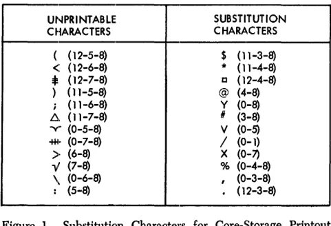
Figure 1. Substitution Characters for Core-Storage Printout and Snapshot Programs
1. The core-storage printout program prints the con-tents of core storage available to the user. It prints from position 001 to position 15500 [7500], in lines of 100 characters, with every ten characters fol-lowed by a blank. Each line of 100 characters is preced.ed by a key line that makes interpretation of the data easier. Blocks of 100 positions that are completely blank are bypa.ssed as far as printing is concerned. The program always prints from posi-tion 101 to posiposi-tion 199 even if they are blank. Po-sition 200 is never printed.
2. All unprintable characters are replaced with stand-ard printable characters (Figure 1). Example: Group marks (12-7-8) are replaced with the printable-character lozenge 0 (12-4-8).
3. All word marks are indicated by I's printed on the next line directly under the characters associated with the word mark.
4. For storage considerations, positions 201-332 and positions 14601M15500 [6601-7500] of core storage
are printed first, with word marks but without char-acter substitution. However, group marks (12-7-8) are replaced with a printable 0 (12-4-8).
5. Each line is labeled on the right-hand side with the appropriate 4- or 5-character address, which desig-nates the lowest core-storage location of that line. The word AREA is printed after the address for easy
recognition of the address by the programmer (that is, XXXOI-AREA).
Identification Card (IDC)
This must be the first card in the Autotest deck. Punch
IDC in collumns 1-3 and program identification data in
any of the remaining columns.
Any number of additional ][DC cards containing com-ments can accompany an object program. These must be placed directly behind the initial IDC card, at the
beginning of the test deck.
If any input data cards for a program are to be stacked in stacker 1, an IDC card with 1 instead of C
punched in column 3 must follow the IDC cards and
precede any of the OBJ, SNP, and/or DTR cards.
Stacker-Identification Cards
Stacker-identification cards are used to identify the punched-card output of the user's program. Autotest punches one or more stacker ID cards and directs the
cards into the correct punch stacker for each program to be tested. Columns 1 and 2 of each stacker-identifi-cation card contain ID and column 3 contains a
punch-stacker identification as follows:
Column 3 Stacker 8 8/2 stacker 4 4 stacker
N Normal punch
Columns 4-80 of the IDC card for the program being
tested are reproduced in columns 4-80 of each stacker-identification card.
Console-Status Card
A console-status card must follow the last IDC card.
The card is used to record the status of the console if a program process error occurs. It is directed into read stacker 1 and is identified by CCC in columns 1-3. Columns 4-80 contain the information punched in col-umns 4-80 of the last IDC card.
Note: Use of the console-status card is optional.
Program Control Card
(PCC)
A program control card must be used with every object deck to be tested or Autotest assumes the following:
1. The object program requires no sense-switch con-trol.
2. Condition of the write-address key-light (ON or OFF) is immaterial during the running of the object
program.
3. There are sufficient unused upper core-storage posi-tions for loading the snapshot and/or disk-trace programs if called for.
If part of an object program is stored in these upper positions of core storage, it could overlay the snapshot and/or disk-trace program. Autotest does not warn the programmer of insufficient core stor-age before loading the object program unless there is a program control card.
4. Autopatch is not to be used.
5. The core-storage printout program is executed auto-matically if an end-of-job condition is reached. If
the program cannot be executed and the operator manually restarts the machine at the Autotest link-age routine, the core-storlink-age printout program is
also executed. In both cases, after the printout is completed, Autotest continues to read cards, search-ing for a print-disk (PRD) utility call card, a tape-print (T/P) call card, a disk-label-program utility call card, a c1ear-disk-storage (CDS) utility call card, a halt (HLT) card, or the next IDC card.
6. Tape drives are not to be used for testing.
When a program control card is used, it is placed immediately following the IDC cards when the
con-sole-status card is not used. Otherwise, it follows the console-status card. It is punched in the follow-ing format:
Columns Contents 1-3 pcc
4-9 Punch from one to six of the alphabetic charac-ters, B, C, D, E, F, G, in any order, to indicate which sense switches must be ON during the run-ning of the object program.
10-14 Punch the 5-character address of the highest core-storage position required by the object pro,:, gram. This address is used to test for sufficient core-storage positions for the snapshot, disk-trace, and autopatch routines. If a snapshot (SNP) or disk-trace (DTR) control card is subse-quently encountered and the core-storage area is insufficient, Autotest prints a message and does not load or execute the routines.
If this field is left blank, Autotest assumes there is sufficient unused upper core storage for the snapshot and I or disk-trace program.
Because autopatch stores patch instructions beginning above the upper core-storage limit specified in these columns, a program control card is required if autopatch is to be used. If a program control card is not present, Autotest causes any autop'atch cards to be bypassed.
15 Specifies write-address key-light requirement for object program.
16
l. Punch'A if the write-address key-light is to be initially on and remains on during the exe-cution of the entire object program. 2. Punch S if the write-address key-light is to be
initially off and remains off during the exe-cution of the entire object program. 3. Punch 1 if the write-address key-light is to be
initially on, but. the setting may be changed during execution. of the object program. 4. Punch 2 if the write-address key-light is to be
be initially off, but the setting may be changed during the execution of the object program.
5. Leave field blank if setting of the write-address key-light is immaterial for running of the object program (no disk write instruc-tions).
Note: Autotest will halt and print a message before running the object program if the write-address key-light setting must be changed be-fore object program execution. However, when combining modes dunng object program execu-tion, the user must program halts and messages when the write-address key setting is to be changed.
A special character is punched if both of the following conditions hold:
Columns
17
18-23
Contents
l. Autopatch is used.
2. The segment-mark special character (0-7-8) is used in the object program.
If a special character is punched, it must be excluded from the object program (see Autotest Specifications - Replacement Character). If one or both of these conditions are not met, the field is left blank.
Punch N if a core-storage printout is not desired, either when an end-of-job condition is reached or when the program execution cannot be com-pleted. When the last instruction (an uncondi-tional branch to the Autotest linkage routine) is encountered or when the machine is manually restarted at the linkage routine (15909 [7909]), the core-storage printout program is bypassed and autotest continues to read cards, searching for a halt (lILT) card, a print-disk (PRD) utility call card, a tape-print (Tip) call card, a disk-label-program utility call card, a clear-disk-stor-age (CDS) utility call card, or the next IDC card.
Leave the field blank if the core-storage print-out program is to be executed.
Note: If the program hangs up (execution cannot be completed) and a manual restart at the Autotest linkage routine is unsuccessful (the linkage routine has been erroneously destroyed), linkage is re-established with a restart deck, deck C. (See Core-Storage Printout.) In this case, a core-storage printout is provided regardless of the contents of column 17 of the pcc.
Punch the numbers of the tape drives to be used during object program execution. Each of these columns can contain any number from 1-6. The tape drives do not have to be specified in any particular order and the punching can begin in anyone of the 6 columns. Use these columns to specify the numbers of the drives on which are mounted: the object program tapes, any tapes used by the tape utility programs, the disk-trace tape, and any precreated tape speci-fied in a lILT card. If tapes are used during object program execution, a pcc card with these columns correctly punched must be provided.
Autotest Optional Features
In addition to the standard functions described in the previous section, the Autotest program provides op-tional features, that can be selected by the programmer to obtain more complete documentation of all object programs. There are two types of optional features, or routines, used by Autotest:
1. Disk Utility and Tape Utility Programs for IBM
1401/1311, which are supplied by IBM for use with
Autotest or with other programs:
• Clear Disk Storage • Disk Record Load • Print Disk
• Disk Label
To use one or more of these utility programs in testing with Autotest, the programmer must gen-erally place a utility call card before the correspond-ing control cards and a utility end card after them. These cards identify the particular utility within the Autotest program to which the control informa-tion applies.
2. Autotest F eatul'es, which can be used only with the Autotest program:
• Snapshot feature • Disk Trace feature • Autopatch.
These features do not require special utility call cards. Control information is placed on the same card that identifies the particular feature. However, snapshot and disk-trace require separate execute cards:, which are placed before the normal execute card in the object program or overlay segment to which the feature applies"
Clear Diisk Storage (CDS)
The clear-disk-storage program can be used before or after program execution if it: is desirable to set certain areas to an initial condition. Punch CDS in columns 1-3 of a card and place behind it the necessary control cards described in this section.
To fill specified areas of disk storage with blanks or any desired IBM 1401/1460 character, place a CDS utility call card in the test deck after the IDC cards and before any of the snapshot (SNP), disk-trace (DTR), or object (OBJ) cards. The CDS card is placed after the data cards following the object program to restore to normal the disk-addressing scheme after modifying it during the execution of the object program.
Normally, before loading a file into disk storage, the file area is filled with blanks. In some cases, however, it is desirable to use 9's or some other character. When a track or record is subsequently read from the disk, unused llocations are easily identified as fields contain-ing only the clearcontain-ing character.
It is usually desirable to restore the normal addresses to a disk pack if they have been modified by the object program. Because the modified addressing scheme must be known to restore the normal addresses, it is important that the programmer use the CDS utility program after program execution when he has modi-fied disk addresses.
An area can be cleared in either the move or load mode, and in either 20-sector or track-record format. The write-address key-light must be ON for execution of the CDS program. It is important that an area be cleared in the mode and format that will be used subsequently to read from that area.
CDS Addresses
The clear-disk-storage program writes the sector ad-dresses in the address portions of the cleared areas. The user has three options from which to choose in writing the addresses.
l. Sequential addresses can be written, beginning with the address given as the lower limit of the area, and continuing through the track containing the upper limit. If the track-record format is used, the ad-dresses written are computed from the upper-limit indication. If the upper limit is given as the zero sector of the track, the addresses written are the zero-sector addresses of each track. If the upper limit is given as the 16th sector of the track, the 16th-sector address of each track is written.
For example, if the limits on the control card are given as 000000-000335, the address written for the first track is 000015, the second track is 000035, the third track is 000055, and so forth. Neither the mode nor the format used need be that in which the area was previously written.
2. The user has the option of writing a set of sequen-tial addresses that are compatible with the address-ing structure on other disk drives in the system. For example, he may clear the area limited by addresses 000000-000219, which refer to the first disk drive in the system, and write sequential addresses 020000-020219, which refer to the second disk drive In this case, the lower limit specified on the control card (see CDS Control Cards) is 020000; the upper limit is 020219. The reference number on the card is 0 because the first disk-drive addresses are pres-ently on the pack.
Again, if track-record format is used, the ad-dress written for each track is computed from the upper-limit indication. Using track-record format in the preceding example instead of 20-sector for-mat, the address written for the first track is 020019, the second track is 020039, and so forth. Neither the mode nor the format used need be that in which the area was previously written.
3. The same addresses as those originally in the area can be rewritten. If this option is taken, the area must be cleared in the same mode (M or L) and the same format (20-sector or track-record) as that in which it was previously written.
CDS Control Cards
The cards are punched in the following format: Columns 1 2-7 8-13 14 15 16 17 18-20 21-40 41-60 61-80 Contents
M or L to indicate move or load mode of op-eration.
6-digit address of the lower limit of the disk-storage area to be cleared. If the addressing structure is to be modified (see CDS Addresses, step 2), the lower limit reflects the lower address desired on the pack after clearing.
Note: The lower limit must be the zero sector of the first track, even if the track does not phys-ically contain a zero sector.
6-digit address of the last sector on the last track to be cleared. (Although anyone of the 20 valid addresses of the last track to be cleared can be used here, the address of the 20th sector pro-vides the greatest time efficiency.) If the ad-dressing structure is to be modified, the upper limit reflects the upper address desired on the pack after clearing.
The upper and lower limit of a disk area must be on the same pack.
Note: If track-record format is being used, for time efficiency the upper limit should reflect the one sector that is used as the track address.
0, 2, 4, 6, or 8 to indicate disk-storage drive containing the area to be cleared.
0, 2, 4, 6, or 8 to indicate disk-storage drive to which the addresses now on the pack refer. (If
retaining same address, punch $.)
The character to which the data portion of the track is to be cleared.
Track format to be used: blank: 20-sector 1: track record
Blank - not used.
}
Control information for up to three addi-tional disk areas to be cleared is punched in the preceding format.
Note: Although the upper and lower limits for a disk area must be in the same pack, the disk areas specified on one control card can be on separate packs.
CDS End Card
Immediately following the control cards is a utility end card. Columns 1-4 of this card are punched ECDS.
Disk Record load (DRl)
A disk-record-Ioad utility call card follows the IDC
card(s) and occurs before any of the SNP, DTR, or OBJ
cards. It is used if the programmer wishes to load addresses, single records, or entire tracks into IBM 1311
disk storage before program-execution time. Punch
DRL in columns 1-3 of the card and place it ahead of
the control-data cards described subsequently. The disk-record-Ioad program reads data from the specified
10
track or sector into core storage, inserts the information from the cards into the desired locations, and writes the data on the disk.
In program testing, this option is often used to set up a sample file of records. It can also be used to modify existing disk records or to change addresses or data on a track.
If one record is placed in several locations on a track, a sector-scan indication in the control card causes the program to change all the sectors with the same address as that specified. If such a sector scan is required, or if an alteration is to be made to a disk address, the write-address key-light must be ON during
execution of the DRL program. Otherwise, it must be OFF.
DRL Input Cards
The disk-record-Ioad program does not require sepa-rate control and data cards. Instead, each input card contains both the data to be inserted and the control information. The first 20 columns of each card contain the required control information. Data to be inserted is punched in the remaining 60 columns.
Any number of input cards can follow a DRL utility
call card in the test deck.
The cards are punched in the following format:
Columns 1 2-7 8-11 12-13 14 15 16 17 18 19 Contents
M or L to indicate move or load mode.
6-digit address of the track or sector to be op-erated upon.
4-digit location of the data within either the sector or track record, depending on which format is used (first position is 0001). If chang-ing a disk address, leave columns 8-10 blank and punch $ in column 11. See Note at the end of this section.
2-digit length of the data field (maximum is 60).
If $ in column 11, leave 12 and 13 blank. 0, 2, 4, 6, or 8 to indicate disk-storage drive on which the pack is mounted.
Blank - not used by Autotest.
Identical disk address option:
1: specifics scan of entire track to alter all records with identical addresses (the write-address key-light must be on if a scan is speci-fied).
blank: if no identical addresses.
Word-mark option:
1: specifies, if in the load mode, that a word mark is to accompany the first character of data. blank: if word mark is not desired or if in move mode.
Track format to be used: blank: 20-sector 1: track record
Columns 20
21-80
Contents Blank - not used.
The data or address to be inserted on the disk pack.
Note: If changing an address, the new address is punched in columns 21-26 and must be a valid one for the track operated on. Columns 2-7 contain the address to be changed. Column 11 contains a $. Columns 8-10, 12, and 13 are left blank. The write-address key-light must be ON when changing disk addresses.
ORL End Card
A utility end card must immediately follow the DRL control cards. Punch EDRL in columns 1-4 of this card.
Print Disk (PRO)
The print-disk program produces a printed copy of an area of disk storage. This program can be executed either before or after execution of the object program, or both. It can print tracks written in either the move mode or load mode and in either 20-sector or track-record format. If desired, special characters that are not printable with the standard 52-character set can be replaced with a printable alphameric or special character.
If a printed copy of a disk area is desired before object-program execution, place a print-disk utility call card in the test deck after the IDC cards and before any of the SNP, DTR, or OBJ cards. For a disk print after execution, place the print-disk card after the data fol-lOWing the object program. Punch PRD in columns 1-3
of the card and place it ahead of the control cards de-scribed subsequently.
PRO Control Cards
Any number of control cards can follow a PRD utility call card in the test deck. From one to four disk areas can be specified on one control card. (A disk area can be from one track to an entire disk pack.)
The cards are punched in the following format:
Columns
1
2-7
8-13
14
Contents
M or L to indicate move or load mode of opera-tion.
6-digit address of the lower limit of the disk-storage area to be printed. Note: The lower limit must be the zero sector of the first track even if the track does not physically contain a zero sector.
6-digit address of the last track to be printed. Although anyone of the 20 valid addresses of the last track can be used to obtain a disk-storage print through the 20th sector, the ad-dress of the 20th sector provides the greatest time efficiency. Note: If track-record format is being used, for time efficiency the upper limit should reflect the one sector that is used as the track address.
0, 2, 4, 6, or 8 to indicate disk-storage drive containing the area to be printed.
Columns 15
16
17
18-20
21-40
41-60
61-80
Contents
Character to be substituted for all special char-acters unprintable with the standard 48-charac-ter print chain.
Leave blank if no character is to be substi-tuted. This option allows faster processing.
\Vord-mark option:
blank: specifics, if in the load mode, that word-mark indications are to be printed.
1: specifies that word-mark printout is not desired in load mode.
Track format to be used: blank: 20 sector 1: track record
Blank - not used
}
Control information for up to three addi-tional disk areas to be printed is punched in the preceding format.
Note: Although the upper and lower limits for a disk area must be in the same pack, the disk areas specified on one con-trol card can be on separate packs.
PRO End Card
Immediately following the PHD control cards must be
a utility end card. Columns 1-4 of this card are punched EPRD.
PRO Print Format
An index, which aids in determining character posi-tions, is ptinted at the top and bottom of each page. In the 20-sector format, the program prints one sector per line. Each line contains an M or L to indicate the mode used to write the sector, followed by the sector address and the record.
In the track-record format, the first line of each track begins with an M or L and the address. The rec-ord is printed beginning after the address. If a new page is started during the printing of a track, the mode and address are reprinted with the first data line on the new page. Each line except the last contains 100 data characters.
When printing areas that are written in the load mode, the user has the option of printing an indication of word marks. A word mark is indicated by printing a one (1) under the character with which it is asso-ciated.
Disk-Label Program
The disk-label program performs all necessary main-tenance operations on the label track of a disk pack. The program is used to:
1. Set up the initial header-label track on a disk pack. 2. Remove the entire label track by clearing it and
restoring the addresses to the original range. 3. Enter a new label.
i
~ ZControl Portion ROLIN Z B
:§ ~
~ These Columns Unused
Ji
0--" JI
J
i! 6 "
J! ;;; u..
I 1516-20 21-24 25-2930 3940-44 45--49 50 51-54 5 5 - - 6 0 61--6667 80
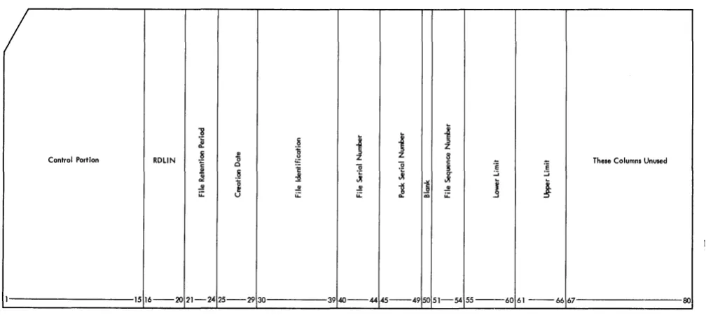
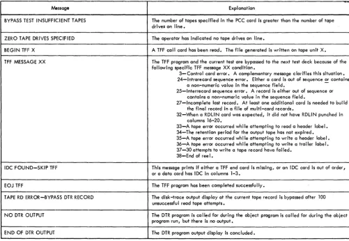
Figure 2. RDLIN Card
5. Ivlake changes to an existing label. 6. Print labels.
7. Punch and print labels.
ROLIN Cards
RDLIN cards are used as input to this program.
Nor-mally, the standard RDLIN card shown in Figure 2 is
used. When it is necessary to operate on fields not contained in the standard RDLIN card, an expanded
XPN2 RDLIN
...
"'0
's
51
~ ~ :.::i
.:!II.' ::::> ~
c
"0 51 ~
c
~
Cii z e::: CI) e::: CI)
1 56 910 1516 2021 26~7 28 3334
/
XPNI RDLIN"8
S ~
~
~
i
ji
E::I
8- c 0 .~ c u Z Z
0 ~ ~ '0
~
1::g
.2 "'0 51 ~ CI) ei
~ ::::> CI) u 3! CI) V)
~ e::: V)
U .:!II.
8. '0 ~ ~ ~ ..!!
~ V) Z u: u: u::: u: ~ u
1 2 56 910 1516 2021 2425 2930 3940 44 45
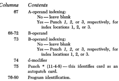
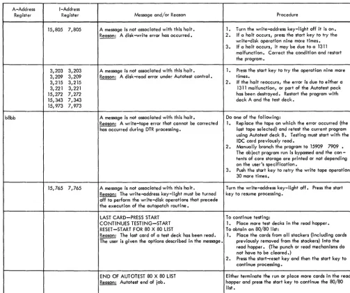
Figure 3. Expanded RDLIN Card Format
...
's
:.::i
format is used (Figure 3). The expanded format con-sists of two cards. The first five columns of the first card are punched as in the standard RDLIN card.
Col-umns 6-9 of the first card contain XPNl. ColCol-umns 1-5 of the second card are left blank, and columns 6-9 of the second card contain XPN2.
Columns 16-20 of both cards contain RDLIN.
The header label fields are punched, as shown in Figure 3, in the same order as they appear in the 100-character disk label.
"'0
~
:S
l
51 "0CI)
Z ::::> e:::
3940 5455 80
j ~ c
u
5 ~l
Z 8 CI) E
CI) .- u CI)
~ -:e g "'Oc "til
..5!! JI C>
!! 15 c :!I
~J C> ~
J
u. Vi~ ~ C
"'0 "'0 ~ .:!II. ~
18
.:!II.~
15 C5 .:!II.c ..!! c 51 51 c g 51
c ..2 c u u
Cii u::: CI) 6~ CI)
Cii u CI) CI)
Cii CI)
0:0 e::: e::: e::: e::: e:::
[image:12.613.41.545.63.296.2] [image:12.613.45.548.440.703.2]Date Card
When the Autotest pack is built, the label track of the pack to be built is checked for unexpired files and a label is generated which protects the area of the pack used for Autotest routines. This label has today's date as a creation date, and a retention period of one day. A date card must be provided with the required
RDLIN cards when a label utility is being executed,
when building the pack with deck A, and when check-ing the header label with deck B. This card, if re-quired, must be the first RDLIN card of the label utility
control cards. The placement of this card in deck A or deck 13 is explained in Operating Procedures. Columns
I-S o 7-11
16-20
Contents
08205
Word-separator character (0-5-8 punches) Today's Date. Punch the year in columns 7, 8 and the day of the year in columns 9-11.
RDLIN
Set Up Initial Header-Label Track (NEW)
The disk pack on which the initial header-label track is to be set up may be previously labeled, contain active labels, or be unlabeled. If the operator does not know the condition of the label track he should use the NEW operation to remove all active labels.
When setting up the initial header-label track, the program performs the following operations:
1. Seeks address OX9980 and changes the addresses on the label track from OX9980-0X9999 to 000180-000199. If address OX9980 is not found, a label track with addresses 000180-000199 is assumed to be on the pack. All previous labels, active or non-active, are eliminated and a new label track is written.
2. Clears all 20 sectors to blanks.
3. Enters the label identifier (lHDRb) and the pack serial number in the first 19 sectors. Only the pack serial number is entered in the twentieth sector. The standard, single-card RDLIN card must be used
for this operation. It is punched as follows:
Columns Contents
1 Disk drive being used 2-4
:5
6-15 16-20 21-44 45-49 50-80
NEW
Disk drive to which the addresses on the pack are referenced
Not used
RDLIN Not used
Pack serial number Not used
The date card is not used with this operation.
Restore Normal Addresses (RNA)
This operation clears the entire label track to blanks and restores the addresses to the range: OX9980-OX9999. The label track on drive 0 cannot be restored by using RNA.
The standard, single-card RDLIN card must be used
for this operation. It is punched as follows:
Contents
Disk drive being used
RNA
Columns 1
2-4
5 Disk drive to which the addresses on the last track are to be referenced
6-9 10-15 16-20
Blank Not used
RDLIN 21-80 Not used
The date card is not used with this operation.
Enter a New Label (ENTR)
This operation is used to enter a complete new header label. The program first searches the label track to insure that there are no unexpired header labels that pertain to files within the limits given in the RDLIN
card. Labels are checked for files within the same relative limits with addresses referenced to other disk drives. Any expired labels pertaining to this area are printed and then deleted. The program then enters the new label from the RDLIN card. The pack serial number
entered in the NEW card is retained, regardless of
whether it is punched in the RDLIN card.
Either the standard or the expanded RDLIN card
format can be used. If the standard format is used, all fields not contained in the RbLIN card are blanked. The RDLIN card is punched as follows:
Columns 1
2-5 6-9 10-15 16-20
Contents
Disk drive being used
ENTR
Blank, XPNl, or XPN2 Not used
RDLIN
The rest of the fields in the RDLIN card, with the
ex-ception of the pack serial number (columns 45-49), are entered in the label. If any fields are left blank, blanks are written in the corresponding positions of the disk label. The lower and upper limits of the area in disk storage to which the label applies must be punched in the RDLIN card.
Delete Labels (DELT)
This operation is used to delete either all of the expired header labels pertaining to files within specified limits or to delete any specific label. If an unexpired label is to be deleted, it must be deleted by specific file identi-fication. All labels deleted are printed.
The standard, single-card RDLIN card is used for this
operation. The RDLIN card is punched as follows:
Columns
1
2-5
6-9
10-15
16-20
21-29
30-39
Contents
Disk drive being used
DELT Blank
Not used
RDLIN Not used
File identification, if a specific header label is to be deleted. Otherwise, these columns are blank.
40-54 Not used
55-66 Lower and upper limits of the areas to which the labels apply, if alliabcls within the limits are to be deleted. Otherwise, these columns are blank. If limits are to be used, columns 30-39 must be blank.
67-80 Not used
The date card must be supplied for this operation if all labels within specified limits are to be deleted.
Change a Label (CHNG)
This operation is used to make changes to individual fields within a header label. The program finds and prints the header label specified in the file-identifica-tion field of the RDLIN card. All non-blank fields in the RDLIN card are then substituted for the corresponding
fields in the header label. The changed label is then printed and written back' onto the label track.
Either the standard or the expanded RDLIN card
format can be used. The card is punched as follows:
Columns 1
2-5
6-9
10-15
16-20
30-39
Contents
Disk drive being used
CHNG
Blank, XPN1 or XPN2
Not used
RDLIN
File identification (must be punched)
All other fields are entered in the corresponding fields of the label if punched.
The date card is not used with this operation.
14
Print Labels (PRNT)
This operation prints either all of the header labels on a disk pack or only specifically requested labels. The standard, single-card RDLIN card is used with this
op-eration. The RDLIN card is punched as follows:
Columns Contents
1 Disk drive being used
2-5 PRNT 6-9 Blank
10-15 Not used
16-20 RDLIN
21-23 ALL, if all header labels are to be printed. 24-29 Not used
30-39 File identification, if specific label is to be printed
40-80 Not used
The date card is not used with this operation.
Punch and Print Labels (PNCH)
This operation punches and prints either all of the header labels on a disk pack or only specifically re-quested labels. The labels are punched in either stand-ard or expanded RDLIN card format. The standard,
single-card RDLIN card is used with this operation.
The RDLIN card is punched as follows:
Columns
1
2-5
6-9
10-15
16-20
21-23
24-29
30-39
40-80
Contents
Disk drive being used
PNCH, if labels are to be punched in the stand-ard RDLIN card format
PNCX, if labels are to be punched in the ex-panded RDLIN card format
Blank
Not used
RDLIN
ALL, if all header labels are to be punched and printed
Not used
File identification, if specific label is to be punched and printed
Not used
The date card is not used by this operation.
Tape-File Generation - Variable-Length Records
maximum record length that can be created is 13,000 [5,000]. Control cards and data cards are required to generate tape files.
Control Cards
There are two types of control cards for variable-length records:
1. The TFV control card calls in the object program and prepares for file generation on the new tape unit. It is punched in the following format:
Colum11s
1··3 4
5
6
Contents
TFV
Tape unit number on which the file is to be created (1-6).
Parity. A B ind.icates odd parity. Any other punch indicates even parity.
Blank
7 -80 Tape-file description
2. The ETFV control card signifies the end of the card-to-tape program. The ETFV card must be included. It is punched in the following format:
Column.s
1··4 5 .. 6 7-80
Data Cards
Contents
ETFV
Blank
Tape-file description
The data cards are punched in the following format:
Columr,rs
1 .. 4
5 .. 6
7-10 11-80
Contents
May contain numeric information for sequen-cing, but this information will not be checked.
WT - -Write tape record
RM - -Record mark TM - -Write tape mark
Blank - Record length exceeds this card ca-pacity.
Blank
Data to be created on the tape
These cards are used to create· the tape file specified by the TFV control card. The data to be created on tape is punched in columns 11-80 in the tape image format. Multiple data cards are used to create larger tape records. Each new record must start in column 11 of a new data card. The end of each record is specified by punching an 11-8··4 (asterisk) one position to the right of the last data character. The use of the asterisk in the control card does not prevent its use within the rec-ord as a character or part of the tape recrec-ord to be created. WT (write tape) must also be punched in
columns 5-6 of the last data card for each record. This causes the record to be written on the tape unit speci-fied in the TFV control card.
A tape mark may be generated on the tape by punching TM (tape mark) in columns 5-6 and leaving
the rest of the card blank. For example, if a tape mark is desired between the data file and a trailer label, a
TM card would be inserted before the first data card
of the trailer label.
Multifile tapes can be created by arrangement of the control and data cards as shown in the following example, which would generate three files on one tape:
TFV card
Data card for file 1
TM card
Data cards for file 2
TM card
Data cards for file 3
ETFV card
When generating blocked records that contain rec-ord marks (0-8-2) as record separators, the user can begin each individual record in the block on a new data card starting in column 11, rather than punch the complete block continuously. Punching RM (record
mark) in columns 5-6 indicates that the record mark used as the record separator is the last character con-tained in this card. All card columns to the right of the last record mark are ignored and only the record mark and the characters to the left are used to build the block. The next individual record of the block must begin in column 11 of the next data card. The last card of the block, as in single records, must have the WT
in columns 5-6 and an 11-8-4 (asterisk) punch follow-ing the last character of the block.
Tape-File Generation - Fixed-Length Records
The Autotest tape file generator can also create files that consist only of fixed-length records. The program transfers data from punched cards to magnetic tape. Although the basic data records, when processed from tape, may remain the same as they were when in cards, it is often desirable to modify the format of the records. Fields that were required in the card file may not be required on tape. The information in master and detail cards may be rearranged and consolidated in the tape records. Exception procedures and field-selection abil-ity are provided in this program to facilitate such modification.
For a better understanding of the fixed-length tape-file generator, the user should read the card-to-tape section of the Systems Reference Library publication: Tape Utility Programs with 120-Character Label
bility for IBM 1401 and 1460: Specifications, Form C24-3156. There are four exceptions to the specifications presented in this publication:
l. Multifile tapes can be created by Autotest only if
the files have identical control-card specifications.
2. The maximum output-tape record size is: 4,000 characters for an 8K machine. 12,000 characters for a 16K machine.
3. The tape rewind and unload option at end-of-job is not provided by Autotest.
4. Only sense switch A is used by Autotest when gen-erating a fixed-length tape file. The settings of the other switches are indicated in the TFF card.
Input Files
Input files must consist of fixed-length records. Each record must begin on a new card. The number of cards per data record must be the same for each record and is limited only by the amount of core storage available for the output tape record (see Output Files), except when performing field selection. In this case, the input record cannot consist of more than 99 cards.
Autotest can produce identical multi-file tapes only if the files have identical control-card specifications. The last file to be written must be followed by a card with /EOF/EO]/ in columns 1-9. When multiple files with identical control-card specifications are processed, each file except the last is followed by a card with /EOF / in columns 1-5.
If tape labels are to be written, a RDLIN card and a user-information card, if necessary, must precede the first record of each file.
Only sense switch A is used by Autotest when gen-erating a fixed-length tape file. The settings of the other switches are indicated in the TFF card.
Output Files
Output files consist of fixed-length data records that can be blocked or unblocked. The blocking factor (number of data records per tape block) is specified in columns 6-9 of the control card. In the event of an in-complete last block, the block is padded with a charac-ter indicated in the control card and is written as a full-length block. Terminal record marks can be in-serted after each record in a block.
The record size and blocking factor used is limited only by the size of the output-tape record that can be accommodated. The maximum output-tape record size depends on machine size:
4,000 characters for an 8K machine. 12,000 characters for a 16K machine.
If tape labels are not written, single tape marks are written at the end of each file and, with multi-reel files, at end-of-reel.
If tape labels are written, the program writes a header label followed by a tape mark before each file and a trailer label preceded and followed by a tape mark after each file. End-of-reel, in the event of multi-reel files, is indicated by an EaR trailer label preceded
and followed by a tape mark.
Sequence Checking
This program can perform two types of sequence checks on the input records:
l. J nterrecord sequence chec\dng is performed by comparing a predetermined field from one record to the next to assure ascending sequence of the records within a file. The field to be compared against can be a maximum of ten digits. It must be in the same location in each input record. Also, it must be an all-numeric field (blanks are converted to zeros) con-tained within one card of the cards comprising each input record. The first sequence number cannot be all zeros. Duplicate numbers are interpreted as a sequence error. Exception records are included in the check.
2. Intrarecord sequence checking is performed by comparing a predetermined field from one card to the next to assure ascending sequence of the cards composing a record. The field is normally one or two positions long, allowing as many as 99 cards per record. When this is the case, the sequence can be-gin again (normally with 01) with the first card of each record. If it is desired to assure ascending se-quence of all the cards within the fi~e, rather than within a single record, this field can be increased to a maximum of ten digits. In all cases, the field must be in the same location in each input card and must be an all-numeric field (blanks are converted to zeros). The first sequence number cannot be all zeros.
Exception Procedures
Records identified by the presence or absence of a field of up to 72 constant exception characters can be by-passed when the card-to-tape operation is performed. A punch in column 16 of the control card specifies that exception procedures are to be followed. A separate card called the exception card is supplied with the con-stant exception characters and the following informa-tion:
2. The length of the exception field.
3. The location of the field within the input record.
The exception field must be contained within one card, and that card mnst be in the same location in each record.
Field Selection
The program can select fields from the input record and arrange these fields in any order in the output record. A field selected for output must be within the limits of one card of the input record. Up to 16 fields can be selected. They are defined in separate field-selection cards in the order of their occurrence in the input record (see Field Selection Cards).
Each field definition specifi.es:
1. The location of the field in the input record. 2. The length of the field (maximum 80 positions). 3. The location in which it is to be inserted in the
output record.
Any positions of the output record that are not used are written as blanks.
Note: If a group mark is present in the high-order position of a selected field, a wrong-length-record error will occur.
Column-Binary Cards
This program can prepare binary tapes from binary cards. Input can consist entirely of column-binary cards or column-column-binary intermixed with BCD (binary-coded-decimal) cards. When processing col-umn-binary cards, each card is treated as a single record. The following operations cannot be performed when processing binary intermixed with BCD records:
1. Sequence checking. 2. Exception procedures. 3. Field selection. 4. Blocking.
5. Group··mark conversion. 6. Record-mark insertion.
When at file contains column-binary cards intermixed with BCD cards, the column-binary cards must have 7 and 9 punches in column 1. The resulting tape records are 84-characters long for BCD cards and 168-characters long for column-binary cards. The last four characters of BCD records and the last eight characters of binary records are written automatically by this program to provide a look-ahead feature that enables a program to distinguish between BCD and binary records during tape reading.
Files that contain all column-binary cards do not require the 7 and 9 punches in column 1. The user can specify that either the first 72 or all 80 columns of each
card be used, producing either 144- or lBO-character-position tape records. IJoak-ahead characters are not written after the records of all-binary files.
Parity
BCD tape records can be written in either even or odd parity. Even parity is written unless odd parity is speci-fied in the control card.
When binary or intermixed binary and BCD records are processed, the binary records are always written in odd parity and the BCD records are always written in even parity. Tape labels are always written in even parity.
Group-Mark Conversion
An IBM 7080 group mark (12-5-8) in cards can be con-verted to an IBM 1400 series group mark (12-7-8) when it is written on tape.
Totals Printout
At the end of each file, the program prints the number of cards read and the number of data records (includ-ing padded records) written on tape.
Note: See Control Card for a summary of the control-card information required.
Tape Rewind
The user specifies in column 17 of the control card which one of the following options he desires at end-of-job:
1. No tape rewind. 2. Tape rewind.
Control Cards
The user must provide three control cards when a tape file consisting of fixed-length records is to be generated. These control cards are:
1. The TFF card, which calls the program used to create the file. This card is punched in the following format:
Columns 1-3 4
5-10
Contents TFF
Output tape unit number (1-6).
These columns are used to indicate the settings of sense switches B-G respectively. A 1 punched in the corresponding column indicates that the sense switch is ON, and any other punch indi-cates that the sense switch is OFF.
2. The program control card which is used to supply the parameters of the file to be generated. This card is punched in the following format:
Columns 1-5 16.2 8-9 10-14 15 18 17 18 19,20 21-25 28 27 28 Contents
Input 1'ecord length. Punch the number of char-acters in each input record. This field must be all-numeric with high-order zeros punched.
Blocking factor (number of data records per tape record). The blocking factor must be all-numeric with high-order zeros punched.
Output record len'gth. These columns need be used only when performing field selection. Punch the number of characters per output data record, not including the terminal record mark if appended by the program.
Tape label code. Punch:
N - if no labels are to be read or written.
1 - if IBM standard 120-character labels are to be written on tape.
2 - if IBM standard 120-character labels on the output tape are to be read and checked on the file-identification field only.
3 - if IBM standard 120-character labels on the output tape are to be read and by-passed.
Exception code. Leave blank if no exception card is used. Punch a 1 if exception procedures are to be performed.
Rewind option. Leave blank if the output tape is not to be rewound at end-of-job. Punch a 1 if the tape is to be rewound.
Parity. Leave blank if the tape is to be written in even parity. Punch a 1 if odd parity is to be used.
Field-selection option. Leave blank if field se-lection is not to be performed. If field-selection cards are used, punch the number of fields to be selected. Punch the high-order zero if re-quired.
Not used.
Group-mark conversion. Leave blank if group-mark conversion is not desired. Punch a 1 if
IBM 7080 group marks (12-5-8) are to be con-verted to IBM 1400 series group marks (12-7-8) and then written on tap~.
Record type. Indicate the record type by punch-ing the correct code as follows:
blank - All BCD
1 - All binary, 80-column records.
2 -All binary, 72-column records.
3 - Mixed BCD and 80-column binary records.
If this column is punched, columns 1-14 must be blank.
Padding character. Punch the character to be used by the program to create padding records
Columns 29 31-35 38-40 41-51 52-80 Contents
that will fill out an incomplete block at the end of a file. The following characters, with their card codes indicated in parentheses, cannot be used for padding:
group mark (12-7-8) record mark (0-2-8) tape mark (7-8) word separator (0-5-8) substitute blank (2-8)
Terminal record-mark option. Punch a 1 if a record mark is to be appended to the end of each record, including padding records, in a tape block.
Creation date. These columns can be used only if a 1 is punched in column 15. Punch the date of the day that the program is being run as follows:
Columns 31-32 - year (i.e., (4)
Columns 33-35 - day of year (001 represents Jan 1, 385 represents Dec 31).
The date punched in these columns is used to check the retention cycle of the output tape and is also the creation date entered in the new header label.
Reel serial number. These columns can be used only if a 1 is punched in column 15. If the re-tention cycle check of the label on the output tape is bypassed, the contents of these columns are used as the reel serial number in the new header label.
Sequence checking. These columns are used to specify the input record field(s) that are to be used to check the sequence of records in a file and the sequence of cards in a record.
Columns 41-45 - Punch the high-order posi-tion of the field within each record that is to be checked for interrecord sequencing.
Columns 48, 47 - Punch the number of char-acters in the interrecord sequence field.
Columns 48, 49 - Punch the number of the column in each card in which the intrarecord sequence- field begins.
Columns 50, 51 - Punch the number of char-acters in the intra record sequence field. Note: Either interrecord or intrarecord sequence checking can be performed without the other.
Leave blank.
3. The /EOF/ card which must follow intermediate files
when a multi-file reel is being created.
4. The /EOF/EO]/ card which follows the data file and
indicates the end of the TFF program. It is punched
in the following format:
Columns 1-9
Field-Selection Cards
One or more field-selection card must be supplied if
field selection is to be performed. The number of se-lected fields determines the number of field-selection cards required. Each field definition requires ten posi-tions, which means that the maximum number, or 16 fields, can be defined in two cards.
Selected fields must be defined in the order of their appearance in the input record. Unused columns must be blank.
Each selected-field definition is punched in ten col-umns as follows:
Positions Contents
1,2 Card number. The program computes the num-ber of cards in each record from the numnum-ber of characters per record.
3, 4 Card column in which the field begins. 5,6 Number of characters in the field.
7 -10 High-order position of the field in the output record.
Exception Card
An exception card must be supplied if exception pro-cedures are to be performed. The format of the card is as follows:
Columns 1-72
73
74,75 76-80
ROLIN Card
Contents
The information that is compared against to identify an exception record. Punch this infor-mation beginning in column 1 and continue as far as necessary.
Exception code. The following codes can be used:
blank - Records identified by the presence of the exception field are bypassed.
1 - Records identified by the absence of the exception field are bypassed.
Number of columns to be compared.
High-order position within the record of the field to be compared.
If a new header label is to be written on the tape by the tape file generator, a RDLIN card containing the
label information must be supplied by the user. The format of the RDLIN card is as follows:
Columns 1-15 16-20 21-24 25-29 30-39'
Contents Not Used
RDLIN
Retention period Creation date File identification
Columns 40-44
45-48
49-52
53
54
55 56
57 58
Contents File serial number Reel sequence number
Leave blank
Density
Checksum
Block sequence
Tape checking/interpreting
Tape data recording technique Tape data processing technique
Creating system
Record format
Record length Blocking factor/size
Checkpoint
Not used 59-62
63
64-68
69-73
74
75
76 Indication of whether a user-information card is supplied or not. If label positions 101-120 are to contain anythin~ other than blanks, supply a user-information card and punch a 1 in this column of the RDLIN card.
77 -80 Not used.
User-Information Card
A user-information card is used if information is to be written in positions 101-120 of the header and trailer labels on the output tape. Punch the card as follows:
Columns Contents
1-20 Information to be written in positions 101-120 of the header and trailer labels.
21-80 Not used.
Tape.to.Printer Program
The Autotest tape-to-printer program prints the con-tents of tape records. Field selection ability (fixed-length records only) is provided to permit the user to specify that only certain fields are to be printed and to specify the desired format of the printed output. If
tape labels are present, the header label of each file encountered is printed.
For a better understanding of the Autotest printer program, the user should read the tape-to-printer section of the Systems Reference Library pub-lication: Tape Utility Programs with 120-Character Label Capability for IBM 1401 and 1460: Specifications,
Form C24-3156. There are five exceptions to the speci-fications presented in thi.s publication:
1. The maximum input-tape record size is:
4,000 characters for"an 8K machine. 12,000 characters for a 16K machine.
2. The program recognizes end-of-job when it proc-esses an ET/P end card instead of by file count or RDLIN card information.
3. A heading line cannot be printed preceding each file when processing multiple files.
4. The tape rewind and unload option at end-of-job is not provided by Autotest.
5. The settings of sense switches B-G are indicated in the T/P call card.
Input Files
This program can process fixed- or variable-length rec-ords, and the tape records can be blocked or un-blocked. If blocked, variable-length records are proc-essed, each record within the block (including the last) must be terminated by a record mark. Because the first four characters of blocked, variable-length tape records are normally a block character count, this program
ex-cludes these positions from the printout. The fifth po-sition of the tape block is considered the first popo-sition of the first data record.
'The