o
Systems Reference Library
IBM 1440 System Component Description
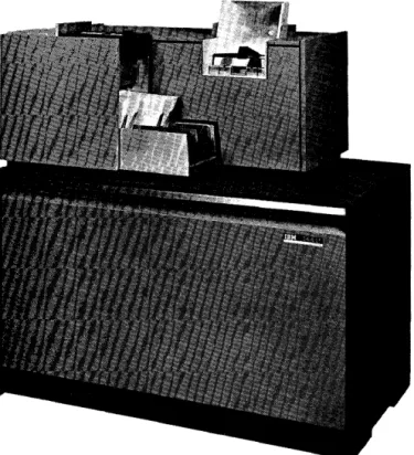
. 1442 Card Read-Punch
1443 Printer
Console Printer
This manual contains a detailed description of the Card
Read Punch, Printer, and Console Printer including the
operation codes for these devices. Also contained in
this manual is a complete description of input/output
timing, samples of program timing, and a description
of a method for determining throughput timing for the
1440 System. A list of input/output instruction times
and a character coding chart are also included.
o
o
Address comments reg arding this publication to :
(
_/)/ INPUT/OUTPUT DEVICES • • . •"':
o
Introduction . • • • • • • IBM 1442 Card Read-Punch IBM 1443 Printer, Modell •• IBM 1447 Console, Model 2 Console Printer . • • • • • •
INPUT /OUTPUT INSTRUCTIONS ••
OPERA TING KEYS, LIGHTS, AND SWITCHES. 1442 Card Read-Punch.
1443 Printer • • • • • • • • • • • • • • • • •
5 5 5 7
8
9
12 12 13
CONTENTS
INPUT/OUTPUT TIMING
...
151442 Card Read-Punch, Modell •• 15
1442 Card Read-Punch, Model 2 •• 17
1443 Printer, Modell 18
Console Printer Timing 20
THROUGHPUT TIMING FOR TI-lE 1440 SYSTEM • 21
Using the Timing Layout Chart.
...
21APPENDIX A
...
27· . ----'-.. -'-_'-_.L.._. ___ .. ___ . __________ J.. __ • _ ••. -, • . • . • - .• - .•• --.--:...J...i..i.-_. _____ . __ •.•
o
o
IBM 1440 Data Processing System
o
o
INTRODUCTION
The IBM 1440 Data Processing System represents a major advance in low-cost data processing systems. Processing methods of the 1440 are similar to those of the IBM 1401 Data Processing System, but the 1440 has input and output devices that enable it to be effec-tive in system areas where there has long been need for a data processing system but not the volume of work to justify such a system.
The IBM 1440 is primarily a file system, pro-viding a group of balanced input/output devices to work in conjunction with the high-speed 1441 Process-ing Unit and the 1311 Disk Storage Drive. The 1440 is a solid-state system with compact components and input/output devices that enable it to be located in an area approximately 15 x 15 feet. Available with the 1440 are the IBM 1442 Card Read Punch (in two models), and the IBM 1443 Printer.
The 1442 Card Read-Punch, Modell, reads cards at a rate of 300 cards per minute (cpm). Punching speed depends upon the last column punched and ranges from 50 cpm, when all 80 columns are punched, to 180 cpm when the first 10 columns are punched.
Model 2 reads ata rate of 400 cpm. Punching speed ranges from 91 cpm when all 80 columns are punched, to 270 cpm when the first 10 columns are punched.
The IBM 1443 Printer,Model 1 is capable of printing from 120 to 430 lines per minute. A print span of 120 positions of alphabetic and numerical data is standard. The print scan can be expanded to 144 positions as a special feature.
IBM 1442 CARD READ-PUNCH
The Card Read-Punch provides the system with card input and output. The 1442 reads cards serially, that
INPUT /OUTPUT DEVICES
is, column by column beginning with column 1 and ending with column 80.
The 1442 reads cards, using the principle of solar sensing to convert light energy to electrical energy. Figure 2 illustrates the path of a card through the solar-sense reading mechanism.
Twelve solar cells, one for each row of punching positions in the card, are exposed to light as holes in the card pass between the light source and the solar cells. This new reading feature makes possible the high-speed serial-reading ability of the 1442 Card Read-Punch.
Figure 2. Solar Cell Reading
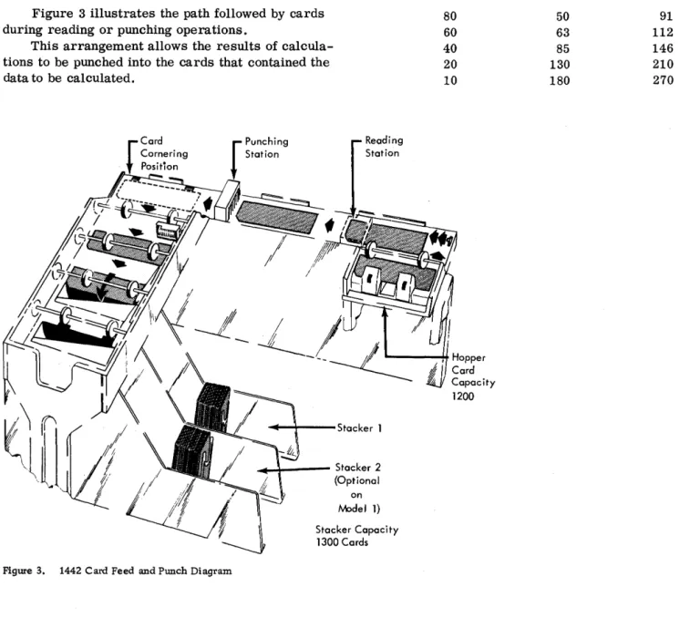
Figure 3 illustrates the path followed by cards during reading or punching operations.
This arrangement allows the results of calcula-tions to be punched into the cards that contained the data to be calculated.
~-+---Stacker 1
... _ - - Stacker 2 (Optional
on IYPdel 1)
After the 1442 punches data into a card, the pro-gram can eject the card into the stacker so that the next card is positioned for punching. Program
re-quirements may demand that the card not be ejected
0
in which case it remains in position (at the nextcol-umn following the last colcol-umn punched) so that the 1442 can punch other calculated results into it in sub-sequent punching operations.
Punching speed depends upon the position of the last column punched.
Last Column Punched
80 60 40 20 10
Capacity 1200
Cards per Minute
Model 1
50 63 85 130 180
Model 2
91 112 146 210 270
o
Stacker Capacity 1300 Cards
Figure 3. 1442 Card Feed and Punch Diagram
o
o
o
If it is necessary to separate reading and punch-ing operations, it is possible to attach an additional 1442 to the system. When this is done, either of the 1442 's can be used to read only, to punch only, or to read and punch.
The read hopper has a capacity of 1200 cards. The stacker is a radial-type stacker, which permits cards to be removed from the stacker without stopping the machine. The capacity of the stacker is 1300 cards. An optional stacker is available for the Model 1 if it is necessary to separate the cards after they have been processed. The Model 2 has two stackers as standard equipment.
IBM 1443 PRINTER, MODE L 1
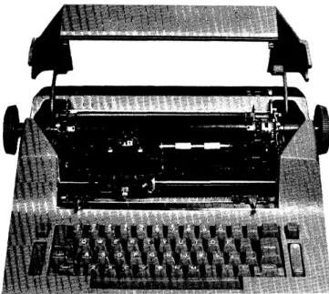
The Printer (Figure 4) is another output medium for the 1440 system. This unit has a rated print-ing speed of 150 lines per minute. With the special Selective Character Set feature, the rated printing speed ranges from 120 to 430 lines per minute. The actual printing speed that can be obtained for a particular job or application depends in part upon the total number of lines to be printed for the job, the amount of processing required for each line that is printed, and the "character set" that is used. The term "character set" is explained in a follow-ing paragraph. The standard number of positions that can be printed on one line is 120, with an additional 24 positions available as a special feature.
Figure 4. 1443 Printer
Horizontal spacing is 10 characters to the inch. Vertical spacing of six or eight lines to the inch can be manually selected by the operator. The vertical spacing between lines is performed by a tape-con-trolled carriage directed from the 1441 stored pro-gram. The sequence and arrangement of data on a line of printing is also controlled by the 1441 stored program.
The 1443 is equipped with a standard 52-charac-ter set: this means that each of the 120 or 144 print pOSitions can print 52 different characters: 26 alpha-betic; 10 numerical; and 16 special characters, namely: &.)::(-
$
* ,
% /
@ ? ! =to :--0 # •With the 52-character set, the 1443 is capable of printing 150 lines per minute. Other character sets are available. The specifications for these character sets are provided in the "Special Features" section.
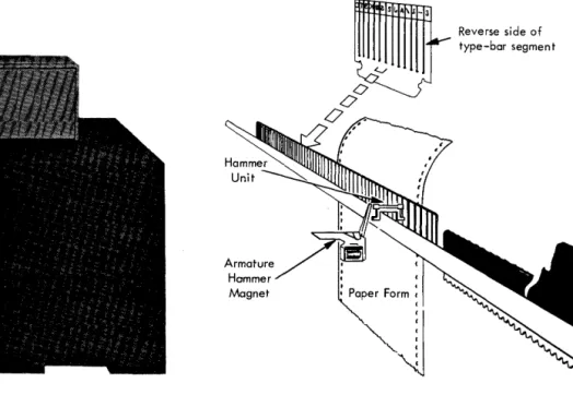
Method of Printing
Alphabetic, numerical, and special characters, are located on a thin metal bar (Figure 5) that travels back and forth in a horizontal plane. As each char-acter is positioned opposite a magnet-driven hammer, the hammer presses the print bar against the paper form and the character prints.
A line to be printed should be assembled in core storage in exactly the same manner in which it must appear as output. Before a character is printed, it is checked against the corresponding position in the print area of core storage to ensure the accuracy of printer output.
Reverse side of
~
~A_3v type-bar segment
Hammer Magnet
0°
0'
IBM 1447 CONSOLE, MODEL 2 CONSOLE PRINTER
The Console Printer is available on the 1447 Model 2 to provide communication between the operator and the processing unit, or between the operator and the disk storage units. The Console Printer can be used for direct input and output to the 1440 system or as a secondary printer. When the high -speed output of the 1443 Printer is not required, the 1447 can be used as the only printer.
Since the Console Printer, under program con-trol, can read from and write into storage, the 1440 system operator can either examine or alter the status ef a particular account, record, or instruction stored in the system.
This feature is especially useful in obtaining in-formation that is in disk storage, such as customers' accmm.ts, stock status data, and payroll details. Through the console printer the operator can request specific data from any disk record, and have the in-formation typed out immediately. This typed copy also serves as a log of information entered into or received from the 1440 system.
The Console Printer also operates in conjunction with the Alter and Character Display modes of the Console Mode switch.
Alter Mode
Data in core storage can be altered by using the following sequence of instructions:
1. Set the Mode switch to ALTER.
2. Set the Manual Address switches to the storage location where the data is to begin. (Data is entered from left to right.)
3. Press the Type key to unlock the keyboard. 4. Type the data to be entered.
5. After all data has been typed, press the Carrier Return key. This returns the carrier and locks the keyboard.
A word mark can be entered into core storage with a data character, by pressing the WM key before the data character is typed. Pressing the WM key causes the Console Printer to print a circumflex and take one space. The word mark is entered into core storage with the next character that is typed.
Figure 6. Console Printer
Character Display Mode
Data in core storage can be displayed by using the following sequence of instructions:
1. Set the Mode switch to CHARACTER DISPLAY.
2. Set the Manual Addres s switches to the storage location of the first character of the data to be displayed. (Data is read out from left to right.)
3. Press the Type key to start the printing of data.
4. Pressing the stop key on the console stops the printing of data.
Word marks are indicated by the printing of a circumflex just prior to printing the character the word mark is associated with in core storage. After the Stop key has been pressed to end the operation, pressing the Type key again resumes the Character Display oper~tion at the next successive higher core storage location.
The Console Printer has character spacing of 10 characters per inch. This spacing provides 85 characters per line.
o
o
o
This section describes the operation codes that the 1440 uses to control card reading, card punching, and printing.
Read Card
Mnemonic OP code A address B address d modifier
R M %Gn
xxx
RThis instruction is used to enter data from the Card Read-Punch into core storage.
The B address specifies the leftmost core stor-age position where the input data will be located. A group mark-word mark must be placed one position to the right of the core storage location where the last character of the input data will be placed. The instruction is stopped by the GM-WM; therefore the number of characters read from the card depends upon the length of the B field that is established. The length of the B field may be from 1 to 80 positions, plus one position for the GM-WM.
Word marks already in the storage positions of
O
the B field are neither considered nor affected. If the length of the data record is longer than the number of positions from the B address to the largest position in core storage, a wrap-around error is cre-ated. For example, in a system with 4000 positions of storage, if the input data consists of 75 characters, and the B address is 3979, the first 20 characters of the input data will be read in 3979 through 3999, and the remaining 55 positions will be placed in core stor-age positions 0 through 54, and the Storage Address light will be turned on.If there is more than one Card Read-"Punch in the system, the last character in the A address designates which Card Read-Punch is to be used.
As the card at the read station is being read, a card at the punch station is being moved past the punch station at the same speed and ejected into the stacker.
Punch Card
Mnemonic OP code A address B address d modifier
PS M
o/oOn
xxx
P This instruction is used to transfer data fromO.
core storage into the Card RePunch. The Bad-! dress specifies the leftmost core storage location of
INPUT/OUTPUT INSTRUCTIONS
the data to be punched. The length of the B field is determined by a group mark-word mark placed ad-jacent to its rightmost core storage position. Data is punched in successive columns of the card at the punch station. When a punch card operation follows a read operation, the card at the punch station station is at column one, and punching begins at column one. When a punch card operation follows another punch card op-eration, the card at the punch station is the card that has been punched in the previous operation, and punch-ing begins in succeedpunch-ing columns of the card, follow-ing the last column punched in the previous operation. This instruction is stopped by the GM-WM, therefore the number of characters punched into the card depends upon the length of the B field.
Word marks within the data being punched are neither considered nor affected.
Punch and Feed
Mnemonic OP code A address B address d modifier
P M
o/oOn
xxx
G This instruction serves the same function as the punch card operation, except that upon completion of the punching operation, the card is advanced com-pletely past the punch station, regardless of the last column punched. The card that was waiting at the read station is advanced so that column one is under the punch station, and a card from the hopper is ad-vanced to the read station. When cards are adad-vanced past the reading station by this operation, data in the cards is ignored. The card that is punched by this operation is advanced past the punch station, and is ejected into the stacker.Word marks within the data field being punched are neither considered nor affected.
(Write a Line)
Mnemonic OP code A address B address d modifier
W M %Y1 X01 W
determined by a GM -WM in its rightmost core storage position. The instruction is stopped by the GM-WM; therefore the number of characters printed depends upon the length of the B field that is estab-lished.
Word marks within the data being printed are neither considered nor affected.
The tens and units position of the B address must always be zero one.
NOTE: The last 100 positions of storage cannot be 'Used for printing operations. (For example, address 3901 cannot be used, when the system contains only 4000 positions of core storage. )
Print and Suppress Space
Mnemonic OP code A address B address d modifier
WS M
%Y1
B01S
This instruction prints a line following which the automatic carriage space is suppressed.
Write Console Printer
Mnemonic OP code A address B address d modifier
WCP M
%TO
xxx
WThis instruction is used to transfer data from core storage to the Console Input/Output Printer. The B address specifies the core storage location of the data to be printed, and the B field is addressed by its leftmost core storage address. The length of the B field. is determined by a group mark-word mark in its rightmost storage position. The instruction is stopped by the GM-WM; therefore the number of characters printed depends upon the length of the B field that is established. Sensing of the GM-WM terminates the operation, returns the print element to the left margin, and causes the Printer carriage to line space. If the field length exceeds the type-writer line length, a print element return and line space are initiated automatically and the printing is continued on the next line until a GM-WM is sensed. Data is printed as it appears in core storage. Should editing of data be required, the editing must be accom-plished by the program before the Write Console Printer operation is initiated.
Word marks within the data field are neither affected nor considered in the execution of this instruction.
Read Console Printer
Mnemonic OP code A address B address d modifier
RCP M
%TO
xxx
RThis instruction is used to enter data into core storage from the Printer keyboard. The B address specifies the core storage location where the input data will be placed, and the B field is addressed by its leftmost core storage address. The operation is normally terminated when the machine operator pres-ses the Carrier Return key. Pressing this key returns the print element to the left margin, effects a line space, and causes a GM-WM to be stored in the next sequential core storage location.
Word marks in the entry area of core storage are neither considered nor affected by this operation.
NOTE: If, during the keying operation, a GM-WM is sensed in the core location next in sequence, the Read Console Printer operation will be terminated, the print element returned, the . carriage line spaced and the keyboard locked.
When the number of data positions to be entered exceeds the number of printing positions in one typewriter line, the print element will automatically be returned from the right hand margin and the entry operation continued on the next line. The number of printing positions in one line is determined by the setting of the margin stops and cannot exceed 85 positions.
Stacker Select (Optional 1442 Modell Card Read-Punch)
Mnemonic OP code d character
SS
K 2This instruction causes the card at the punch station to fall into stacker 2. Unless stacker 2 has been selected before the operation that ejects the card (Read or Punch and Feed), the ejected card is directed to stacker 1.
Word marks are not affected.
Control Carriage
Mnemonic 0 P code d character
CC F
x
o
o
o
o
o
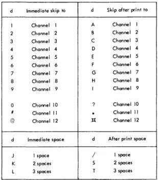
This instruction causes the Printer Control carriage to move as specified by the d character in one of the following ways:
1. A digit causes an immediate skip to a spec-fied channel in the carriage tape.
2. An alphabetic character containing a 12 zone causes a skip to a specified channel after the next line is printed.
3. An alphabetic character containing an 11 zone causes an immediate space.
4. An alphabetic character containing a zero zone causes a space after the next line is printed.
Figure 7 shows the function of the d character. If the carriage is in motion when a CONTROL CAR-RIAGE instruction is given, the program stops until the carriage comes to rest. At this point, carriage action is initiated again, and then the program advan-ces to the next instruction in storage.
Word marks are not affected.
d Immediate skip to d Skip after print to
1 Channel 1 A Channel 1 2 Channel 2 B Channel 2
3 Channel 3 C Channel 3
4 Channel 4 D Channel 4
5 Channel 5 E Channel 5
6 Channel 6 F Channel 6
7 Channel 7 G Channel 7 8 Channel 8 H Channel 8
9 Channel 9 I Channel 9
0 Channel 10 ? Channel 10
/I Channel 11
.
Channel 11 @ Channel 12 ):{ Channel 12d Immediate space d After print space
J 1 space / 1 space K 2 spaces S 2 spaces
L 3 spaces T 3 spaces
OPERATING KEYS, LIGHTS, AND SWITCHES
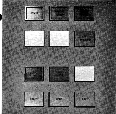
1442 CARD READ-PUNCH (Figure 8)
Power Light
This light indicates that power is applied to the Card Read-Punch control circuits.
Validity Check Light
This light is turned on when an invalid combination of punches occurs in the card column being read. If the I/O Check Stop switch is off, a program test will turn the Validity Check Light off. If the I/O Check Stop switch is on, pressing the Check Reset key on the con-sole will turn the Validity Check light off.
Punch Check Light
This light is turned on when an error is detected in output punching. If the I/O Check Stop switch is off, this light is turned off by a program test. If the I/O Check Stop switch is on, this light is turned off by pressing the Check Reset key.
Card Register Light
The light is turned on when a card is fed which is sufficiently off register, either in punching and/or in feeding, to prevent accurate data transfer. If the I/O Check Stop switch is off, this light is turned off by a program test. If the I/O Check Stop switch is on, this light is turned off by pressing the Check Reset key on the console.
Ready Light
This light indicates that the Card Read-Punch is pre-pared to accept instructions from the Processing Unit. The following conditions are required:
1. Power on
2. Cards registered at the punch and at the read stations.
3. Cards in hopper
o
4. Stacker not full5. No error conditions
NOTE: After run-in, a card need not appear at the punch station. If the first operation calls for punching, a read and eject cycle will auto-matically be initiated before punching occurs.
Feed Check Light
This light is turned on when a card is mispositioned in the card path, or-a Read Station Lamp Check occurs. The Read Station Lamp Check determines that all the lights in the solar-cell reading mechanism are func-tioning properly. The light will be turned off by the following action.
Card mispositioned Run out cards (clear jam if necessary). Run in cards with Read Punch start.
The IBM Customer Engineer must be called if there is a solar-cell lamp check failure.
Start key
To run in 1. Power on 2. Card path empty 3. Cards in hopper
4. Press Read Punch Start key to feed one card. Ready light comes on.
To restore to ready status after
manual stop Press Read Punch Start key
Stop key
Removes the Read Punch from ready. The system is unaffected unless the Read Punch is selected by the program.
o
Figure 8. 1442 Operating Keys and Lights
&-onprocess Runout Key
This key is used to eject cards from the card path, without processing them. The key is ineffective un-less the Read Punch is removed from ready status and the hopper is empty.
Last Card Sequence (Sense Switch A on Console)
The last card operation provides the logical means of terminating an application after the final card has been processed. The sequence is initiated when the last card has been fed from the hopper into the read station and the system is stopped. The operator then
1. turns Last Card switch on (Sense switch A, Console Panel), and
2. presses the Read Punch Start key.
This releases the interlock and allows the remain-ing card to be read and processed as the program requires. As the card passes the read station the
O
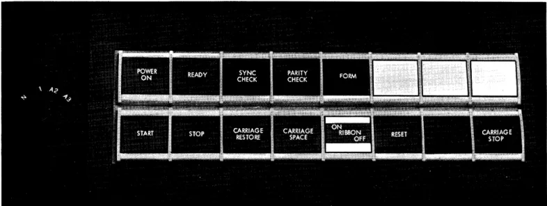
last card indicator is turned on for subsequent . te sting (B IlIA)1443 PRINTER (Figure 9)
Power On Light
This light indicates when DC power is applied to the Printer control circuits.
Ready Light
This light indicates that the printer has been condi-tioned by the operator to accept instructions from the processor. It is turned off when the Stop key is pressed, when an error is detected, or when the Printer runs out of forms.
SYNC (Synchronization) Check Light
This light is turned on when the type bar is not prop-erly synchronized. When this occurs, the Printer is removed from Ready. Pressing the Printer
Reset key turns the light off.
Parity Check Light
This light is turned on when a parity error is detected by the error check circuits. It is turned off when the Check Reset key on the Console is pressed, or when the Parity indicator is program-tested.
Form Light
This light is turned on when approximately four inches of the last form remain to be printed. When this occurs, the Printer is automatically removed from ready status. Pressing the Start key will cause the remaining lines of the form to be printed, one at a time, each time the Start key is pressed.
Start Key
Pressing this key with power on and with printed forms in position places the 1443 Printer in a ready status to accept instructions from the 1441 Processing Unit.
Pressing this key with the Forms light on causes the Printer to take only one print cycle, if the pro-cessing unit directs the Printer tQ do so.
Stop Key
affected unless the program selects the Printer in a not-ready status.
Carriage Restore Key
Pressing this key positions the carriage at channel 1. If the carriage feed clutch is disengaged, the form will not move. If it is engaged, the form will move in syn-chronization with the control tape.
Carriage Space Key
Pressing this key causes the form to advance one space.
Ribbon Switch
When this switch is turned off, the ribbon and the mechanism of the print bar stop and the latter is disengaged. This switch must always be turned off
Figure 9. 1443 Operating Keys and Lights
,.,,,.,,,, .. ,.,,,."".",,, ... ,,, .... ,,,,., ... , ... _".,.,, ... _-",,, ... '."" ",.""".". __ ... """"
before the ribbon is changed or the type bar is re-moved. For normal printing operation, this switch must be turned on.
Reset Key
Pressing this key resets all Printer check circuit indicators.
Carriage Stop Key
Pressing this key stops carriage operation and re-moves the Printer from ready status.
Carriage Clutch Knob (not shown in Figure 9)
The Carriage Clutch controls the carriage tape drive and the form feeding mechanism. If it is set to neu-tral, automatic form feeding cannot take place.
o
o
•
o
•
o
,
o
1442 CARD READ-PUNCH, MODEL 1
Card Reading
Cards are read at two speeds: 285 cpm and 300 cpm. Either of these speeds is possible if the card read instruction is given within certain bounds. The 285 cards per minute cycle is:
Read Time
10 ms 126 ms
Eject and Register
54 ms
Clutch
Latch Point
20 ms
. 2 1 0 m s
-If 80 columns of a card are read and the Card Read instruction is given during the 20 ms at the end of the total card read cycle of 210 ms, then a rate of 285 cards per minute will be achieved. If less then 80 columns are read, there is commensurately more time available for computation.
T = .0111
(Lr
+ 1) + 10 + ~1 + 1. 3 (LB + 1U (1)The figures in the bracket represent that portion of the total card cycle during which the card is actually being read and the 10 represents the clutch pickup time. (LB + 1) is the number of card columns being read plus an additional cycle that is required to sense the terminating group mark-word mark in core storage. Formula (1) can be consolidated as follows:
.1 ms 10.0 21.0
~
32.4
Instruction Time. 0111
(Lr
+ 1) Clutch Pick upTime to read the GM-WM
T
=
32.4 + 1. 3LBThe time available for the computation to take place within the card read time (overlap) is given by the following formula:
C
=
210 - T (2)The following table shows representative times based upon formula (1) and formula (2).
INPUT jOUTPUT TIMING
No. of Card Columns Read
1 40
80
Interlocked for Reading {ms}
33
84
136
Process Time Avai lable (ms)
177
126
74
*Assuming four instructions per millisecond.
Approximate No. of Instructions Executed*
708
504 296
If the Card Read instruction is given before the last 20 ms of the card read cycle, the clutch will still be engaged and 10 ms will be deleted from the total cycle, assuming all 80 columns are read, as follows:
Read Time
126 ms 54 ms 20 ms
2 0 0 m s
-The above cycle is equivalent to a rate of 300 cpm. The formula to compute read time is now
T= 42.4+ 1. 3LB
The clutch pickup time (10 ms) is eliminated, but the program will be interlocked for the 20 ms beyond the clutch latch point. The formula to compute the computation time available for overlap must be adjusted as follows:
C = 200 - T (3)
The following table shows representative times based upon formula (3).
No. of Card Columns Read
Interlocked for Reading {ms}
Process Time Avai lable (ms)
Approximate No. of Instructions Executed 1 40 80 43 94 146 157 106 54 628 424 216
If the total cycle exceeds 210 ms, that is, if the card read time and the computation or other time is greater than 210 ms, then there is a corresponding drop in the number of cards read per minute. The formula to compute the effective number of cards read per minute is as follows, where X is the elapsed time between card read impulses and it is greater than or equal to 210 ms:
The following table shows representative times based upon formula (4).
Cycle Time X (ms)
Approx. No. of Instructions Executed per Cycle
210 300 400 500 Card Punching 285 200 150 120 840 1200 1600 2000
The 1442 Card Read-Punch punches a column in 12.5 ms. 210 ms is necessary to move the card from the read station to the punch station and can be overlapped with computation time according to the rules for reading. A Punch and Feed instruction makes all 210 ms available for overlap. If reading and/or computation can be confined to this 210 ms period, then the following formula provides the number of cards punched per minute:
cpm= 60,000
12.5 LB + 210
The following table shows representative speeds based upon formula (5).
Columns
Punched cpm
1 270
20 130
40 85
80 50
(5)
If the total cycle time is greater than 1210 ms the time required to punch 80 columns plus 210 ms -the formula for -the number of cards punched per minute is given by the following, where X is the time between punch instructions and is greater than or equal to 1210 ms.
cpm = 60,000
X (6)
The following table shows representative speeds.
Cycle Time X (ms) cpm
1210 50
1300 46
1400 42
2000 30
At certain times, a program may call for the reading of a card, processing of the information, and then subsequently punching into the same card. It is important to consider the card design in such cases.
For example, suppose a card containing 40 columns of information is read into the system. Subsequently, 40 columns are to be punched into the same card. If columns 1-40 were to be read, and columns 41-80 to be punched, then a graphical representation of the operation would be as follows:
Read Ccrd
Compute
Punch Card
210
126 1---1
1000
Using formulas (1) and (2), the overlap available when reading 40 columns is 126 ms. Since the last
40 columns are to be punched, the LB field in core storage must be 80 characters in length, of which the first 40 are blanks. Although no punching takes place for the blank columns, 12. 5 ms is involved for every card column skipped until column 41 is positioned under the punches, at which time signifi-cant data is punched into the remaining 40 columns. Hence, the total punch time is 80 x 12.5= 1000 ms for a total cycle time of 1210 ms.
Now consider the reverse card design situation. Suppose the last 40 card columns of the card were read and the first 40 columns were punched. The cycle would then be as follows:
Read Card 1-1 ---=2::...:..10-=---1
Compute
Punch
74
f---l
500
Although only the last 40 columns contained data, the entire card was read in order to get this data into core storage. Hence, for the determination of overlap time, an 80-column card is considered as being read and formulas (1) and (2) give an overlap time of 74 ms. Since only the first 40 columns are to be punched, the punch time is thus, 12.5 x 40= 500 ms for a total cycle time of 710 ms. It is assumed that computation time can be performed within card read time. If not, there is still considerable ad-vantage to organizing the card form as shown in the second example above, since an additional 500 ms are gained by this method. In the first case, the cycle time is 1210 ms and the throughput is 50 cpm. In the second case, the cycle time is 710 ms and the throughput is 85 cpm, a significant increase in card throughput.
In the operation of reading a card and then punching into the same card, the total cycle time
o
..
o
•
,
o
•
o
o
can be determined from formulas (5) and (6), since overlap depends upon the card read portion of the
.~
cycle and punching time is the same in both cases. As mentioned, however, card design is quite important in this case.
1442 CARD READ-PUNCH, MODEL 2
Card Reading
The Model 2 reads at either 375 or 400 cpm, depending upon when the card read instruction is given.
Eject and Register
Read Time
Clutch Latch Point
10 ms 96 ms 39 ms 15 ms
~.~---160ms---~.~
The basic cycle is 160 ms (equivalent to 375 cpm), which is reduced to 150 ms (400 cpm) if a card
read instruction is given prior to the last 15 ms of the end of the card read cycle. Reading time for a card is given by the following formula:
T = .0111
(~+
1) +10 +~5
+1. 0 (LB + 1D (7)Here, the 10 is the clutch pickup time and the quantity in the bracket represents the time actually spent in reading the card. This formula can be consolidated to:
T
=
26. 1 + 1. 0 LBThe time available for overlapping computation is given by:
C -= 160 - T (8)
The following table shows representative times based upon formulas (7) and (8).
No. of Card Interlocked
Columns Read for Reading (ms) Overlap {ms}
I 27 133
40 66 94
80 106 54
If a card read instruction is given before 15 ms of the end of the cycle, a rate of 400 cpm can be achieved.
Read Time
96 ms
Eject and Register
CI",h
I
Latch Point
39ms 15ms
....1---
150 ms!-The formula to compute read time is now:
T = 31. 1 + 1. 0 LB
The formula for determining the overlap time available for computation is now:
C= 150 - T (9)
The following table shows representative times based upon formula (9).
No. of Card Interlocked
Columns Read for Reading (ms) Overlap (ms)
I 32 118
40 71 79
80 III 39
If the total cycle is greater than 160 ms, the following formula, with X ~ 160, provides the number of cards per minute:
cpm= 60~00
(10)
The following table shows representative speeds based upon formula (10).
Length of Cycle cpm
Card Punching 160 200 300 500 375 300 200 120
The Card Read-Punch punches a column in 6.25 ms. 160 ms is necessary to move the card from the read station to the punch station and can be overlapped according to the rules of reading. A Punch and Feed instruction allows 160 ms to be overlapped. The following gives the number of cards punched per minute:
_ 60,000
cpm-6.25 LB + 160 (11)
The following are some representative times:
If the total cycle is greater than 660 ms, which is the time required to pWlch an 80-column card, the following formula, with X equal to or greater than 660 , applies:
60,000 cpm=
--'---X (12)
The following table shows representative speeds based upon formula (12).
Cycle Times {ms} 660 750 900 1000 90 80 66 60
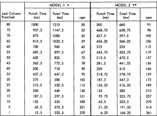
Figure 10 shows card read time and the overlap time available for processing of all 80 columns of a card in increments of 5 columns. Figure 11 shows card pWlching time, the overlap time available for pWlching, and the equivalent card-per-minute speed.
Reading in ConjWlction with PWlching
Many applications involve a combination of reading and punching. The pWlching speeds in Figure 12 are based on a program of reading a card, performing calculations on its data, and punching results in the same card.
MODEL I at 285 cpm MODEL 2
Cols. Process or Overlap Card Read Cols. Process or Overlap Read Time (ms) Available Time (ms) Read Time (ms) Available
80 74 136 80 54
75 81 129 75 59
70 87 123 70 64
65 94 116 65 68
60 100 110 60 74
55 107 103 55 79
50 113 97 50 84
45 120 90 45 89
40 126 84 40 94
35 133 77 35 99
30 139 71 30 104
25 146 64 25 109
20 152 58 20 114
15 159 51 15 119
10 165 45 10 124
5 172 38 5 129
I 177 33 I 133
Figure 10. Card Read Times
The emphasis in this type of application is not placed on the number of columns punched but where the punched columns are in the card. With the Modell, punching the 5 columns in the beginning of the card gives 118 cpm greater throughput than pWlching columns 26 to 30; with the Model 2, throughput is increased by 149 cpm.
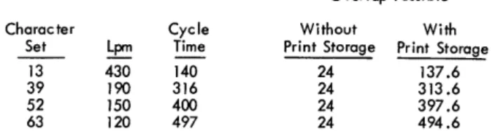
1443 PRINTER, MODEL 1
The Printer can accommodate four different character sets. The speed of each model depends upon the set used. The amount of time available for overlapping operations is 24 ms in all cases. The following table gives the lines per minute for corresponding character sets:
Char. Cycle
Set Lpm Time Overlap {ms}
13 430 140 24
39 190 316 24
52 150 400 24
63 120 497 24
The 24 ms at the end of the cycle permit the spacing or skipping of two lines within this time. Each additional line skipped or spaced requires an additional 10 ms. This period of time must be allowed for in the over-all cycle time.
If the time between print operations exceeds the total print cycle for any given character set,
at 375 cpm Card Read Time (ms)
106 101 96 91 86 81 76 71 66 61 56 51 46 41 36 31 27
o
o
•
,
o
•
o
o
MODEL 1 •
Last Column Punch Time Total Time Punch Time Punched (ms) (ms) cpm (ms)
80 1000 1210 50 500 75 937.5 1147.5 52 468.75 70 875 1085 55 437.5 65 812.5 1022.5 59 406.25
60 750 900 63 375
55 687.5 897.5 67 343.75 50 625 835 72 312.5 45 562.5 772.5 78 281.5
40 500 710 85 250
35 437.5 647.5 93 218.75 30 375 585 103 187.5 25 312.5 522.5 115 156.25 20 250 460 130 125 15 187.5 397.5 151 93 75 10 125 335 180 62.5
5 62.5 272.5 221 31.25 1 12.5 222.5 270 6.25 * 210 ms of process time avai lable during card movement time
•• 160 ms of process time avai lable during card movement time
Figure 11. Card Punch Times
formula (13) should be used to obtain the correspond-ing lines per minute, with X, the time between print operations as follows:
X~ 140 13 - Character set
X~ 316 39 - Character set
X~ 400 52 - Character set
X~ 497 63 - Character set
I 60,000
pm=-X-- (13)
Available with the Printer is a Print Storage Feature, which permits an overlap during most of the print cycle. The execution time for a print instruction when the Print Storage feature is installed is:
T=2.4 ms (14)
This time includes the instruction time and the time required by the processing unit to place
MODEL 2 . .
Total Time
(ms) cpm 660 91 628.75 96 597.5 100 566.25 106 535 112 503.75 119 472.5 127 441.25 136 410 146 378.75 159 347.5 173 316.25 189 285 210 253.75 237 222.5 270 191. 25 314 166.25 361
MODEL 1 MODEL 2 Columns to
be Punched Cards per Minute Cards per Minute
1 - 5 221 314
6 -.• 10 179 270
11 - 15 151 236
16 - 20 130 210
21 - 25 115 189
26 - 30 103 172
Figure 12. Card Punch Times - Punching into a Card Just Read
Process overlap time available is the difference between 2.4 ms and the corresponding cycle times for the different character sets. For example, for the 52-character set,
Overlap= 400 - 2.4 (15)
Figure 13 shows the effect of the Print Storage Feature.
Character
Set Lpm
13 430 39 190 52 150 63 120
Cycle Time
140 316 400 497
Overlap Possible
Without With
Print Storage Print Storage 24 137.6 24 313.6 24 397.6 24 494.6
Figure 13. Printing TIme - with and without Print Storage
CaNSO LE PRINTER TIMING
The console printer serves as both input and output for the 1440 system. In either of these modes, it is
an unbuffered operation. No overlap time is available. The timing of the console printer is:
Input
T = .0111 (LI +1) +Operator Keying Time Output
T = .0111 (LI +1) +68 (LB) +800 (CR-1)
The only possibility of overlap time in either of these operations comes on the last carrier return which signals the end of the respective operations. Thus, the time needed to print out two lines of 50 characters each is:
.0111 x 8 68 x 100
1 x 800
.088 ms 6800.000 rns
800.000 rns * 7600.088 rns
*The second carrier return is overlapped by processing.
o
•
o
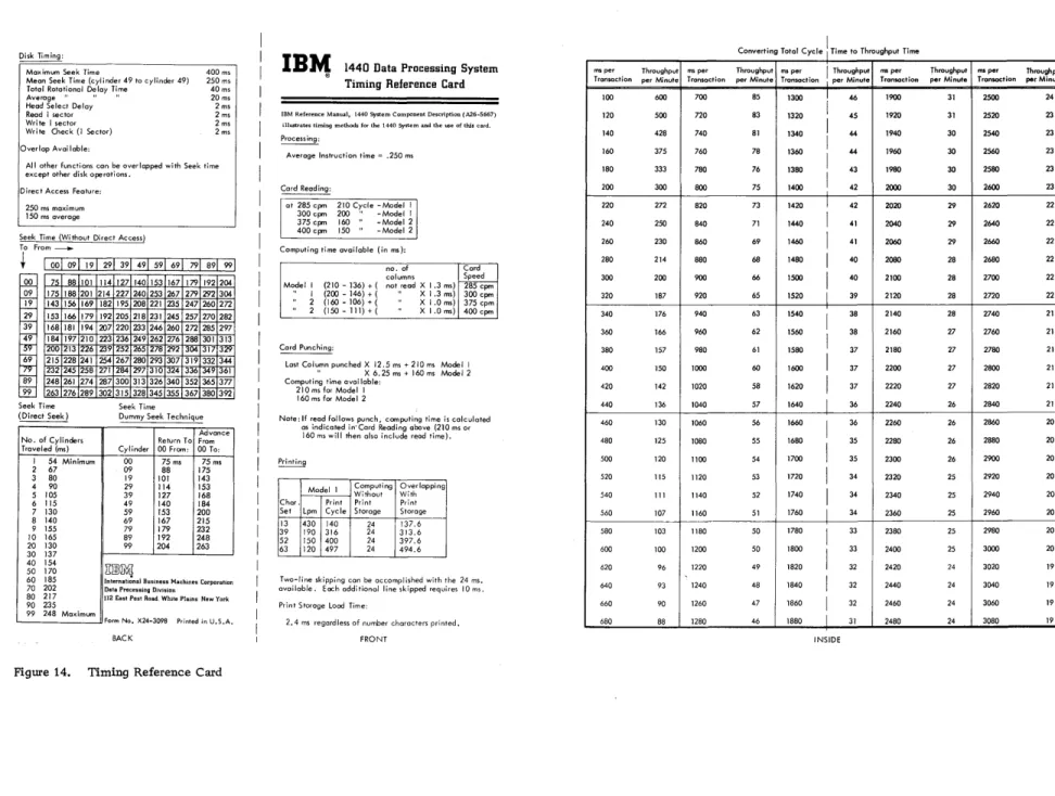
The Timing Reference card in Figure 14 and the Tim-ing Layout Chart in Figure 15 are available as aids to developing throughput times. The information in the Timing Reference card consists partially of material summarized from the timing considerations provided in this Manual and the timing considerations provided in 1440 System Component Description, 1311 Disk Storage Drive (Form A26-5668). The same principles used in the Timing Layout Chart has been used in previous examples.
The remaining portion of this manual des cribes how a 1440 program can be indicated on the Timing Layout Chart and how the throughput time for each transaction can be calculated.
USING THE TIMING LAYOUT CHART
The Timing Layout Chart is designed to show the basic operations the 1440 System is performing. If it is used with care and discretion, it can give a very good idea not only of how to time out an application, but of how to judiciously program it as well. Suppose
O
there is an operation involving the reading of a card, the processing of data from the card, the printing of a line and the punching of that line into the s arne card.o
In this example, forms design is important because how the last 40 columns are programmed to be read and how the first 40 columns of the same card are programmed to be punched will affect the speed of the operation. In this operation it is assumed that the Print Storage feature is not installed.
The first operation, reading the card, takes 210 ms. This line is drawn to scale as all others. The formulas in the Timing Reference Card show that 74 ms of the card read cycle are available for processing. During this time a seek is initiated which on the aver-age takes 250 ms. Since this seek is purely on a ran-dom basis and there is no fore knowledge of when the record will be found, the maximum time for finding it (250 ms) must be allowed before processing is started.
When the proper cylinder has been found, it is necessary to wait until the appropriate sector has come under the read-write heads before Read Disk Time is started. This may take anywhere from 0 to 40 ms. An average rotational delay of 20 ms is shown. From this point on, however, assuming that it has taken 20 ms to find the record, it must be assumed that the same sector will be available every 40 ms, and this relationship should be taken advantage of in
THROUGHPUT TIMING FOR THE 1440 SYSTEM
determining the write disk and write disk check times. As shown, it takes 4 ms to read the disk and proces-sing of the record follows it. If the record is subse-quently to be written back onto the same sector in the same cylinder, the crucial point in the timing is the number of revolutions the disk has made by the time the record is ready to be written back on its respec-tive cylinder. It is important to note that whenever the cylinder addressed is the one just used in a prior operation, no Seek instruction is required, because the cylinder is still under the read-write heads. The only delay is the delay caused by the rotation of the individual disk itself. This analysis is shown by the increments of 40 ms laid off on the line depicting Rotational Delay. In this way, one can determine when it is possible to perform the next disk operation.
Processing time can be estimated at about. 250 ms per instruction. In this case, process time can be assumed to be approximately 96 ms. As can be seen from Figure 16, a process time of approxi-mately 96 IDS involves waiting for the cylinder to
be properly positioned. If a write disk operation of 4 ms is depected, there will be another delay of 20 ms until the sector again comes under the read -write heads, and the time for the write check operation begins. At the conclusion of this cycle (approximately 570 ms) the print operation begins. The print operation is started before the punch operation in order to overlap the two during the last 24 ms. Total cycle time, for this example is 1446 ms, the equivalent of 41 transactions per minute.
The total cycle time in milliseconds can be con-verted to throughput time in minutes by dividing the total cycle time into a constant of 60,000 (see Timing Reference Card, Figure 14). This table shows total cycle times, ranging from 100 ms to 3080 ms, in increments of 20 ms, and the corresponding through-put times in minutes. In using this table, one should take the total cycle time, find a corresponding, or" closely corresponding, time from the "millisecond" column of the table, and note the number opposite the millisecond figure which is the total number of trans-actions that can be processed in one minute. This number, divided into the total number of transactions in a job, will give the total job time.
N N
Disk Timing:
Maximum Seek Time 400 ms
250 ms 40ms 20 ms 2ms Mean Seek Time (cylinder 49 to cylinder 49) Total Rotational Delay Time
Average" " II
Head Select Delay Read I sector Wri te 1 sector Write Check (I Sector)
2ms 2 ms 2 ms Overlap Avai lable:
All other functions con be overlapped with Seek time except other disk operations.
Direct Access Feature:
250 ms maximum 150 ms average
Seek Time (Without Direct Access) To From---.
+
I __ I __ I __ I __ I __ I __ I __ I r -QQ 09 }1 29 39 49 69 ~ 89 9975 88 175 188 143 156 153 166 168 181 184 197 200 213 215 228 232 245 248 261 263 276 Seek Time (Direct Seek)
101 201 169 179 194 210 226 241 258 274 289
No. of Cylinders Traveled (ms)
I 54 Minimum 2 67 3 80 4 90 5 105 6 115 7 130 8 140 9 155 10 165 20 130 30 137 40 154 50 170 60 185 70 202 80 217 90 235 99 248 Maximum
114 127 140 153 167 179 192 204 214 227 240 253 267 279 292 304 182 195 208 221 235 247 260 2n 192 205 218 231 245 257 270 282 207 220 233 246 260 2n 285 297 223 236 249 262 276 288 301 313 239 252 265 278 292 304 317 IJ~
254 267 280293 307 319 332 344 271 284 297310 324 336 349 361 287 300 313 326 340 352 365 377 302 315 328 345 355 367 380 392
Seek Time Dummy Seek Technique
Advance Return To From Cylinder 00 From: 00 To:
00 75 ms 75ms 09 88 175 19 101 143 29 114 153 39 127 168 49 140 184 59 153 200 69 167 215 79 179 232 89 192 248 99 204 263
m]l~
International Business Machines Corporation Data Processing Division
112 East Post Road. WhIte Plams New York
Form No. X24-3098 Printed in U.S.A.
BACK
Figure 14. Timing Reference Card
IBM
® 1440 Data Processing SystemTiming Reference Card
IBM Reference Manual, 1440 System Component Description (A26-5667) illustrates timing methods for the 1440 System and the use of this card.
Processing:
Average Instruction time = .250 ms
Cord Reading:
at 285 cpm 210 Cycle -Model I 300 cpm 200 " - Model I 375cpm 160" -Model 2 400 cpm 150" - Model 2 Computing time available (in ms):
no. of Card columns Speed Model I (210 - 136) + ( not read X 1.3 ms) 285 cpm
., I (200 - 146) + ( " X 1.3 ms) 300 cpm 2 (160 - 106) + ( X 1.0 ms) 375 cpm 2 (150-111)+( XI.Oms) 400cpm
Card Punching:
Last Column punched X 12.5 ms + 210 ms Model I " X 6.25 ms + 160 ms Model 2 Computing time avai lable:
210 ms for Model I 160 ms for Model 2
Note: If read follows punch, computing time is calculated as indicated in· Card Reading above (210 ms or 160 ms will then also include read time).
Printing
Model I Computing Overlapping Without With Char. Print Print Print Set Lpm Cycle Storage Storage 13 430 140 24 137.6 39 190 316 24 313.6 52 150 400 24 397.6 63 120 497 24 494.6
Two-line skipping can be accomplished with the 24 ms. available. Each additional line skipped requires 10 ms. Print Storage Load Time:
2.4 ms regardless of number characters printed. FRONT
ms per Throughput
Transaction per Minute
100 600 120 500 140 428 160 375 180 333 200 300 220 272 240 250 260 230 280 214 300 200 320 187 340 176 360 166 380 157 400 150 420 142 440 136 460 130 480 125 500 120 520 115 540 III 560 107 580 103 600 100 620 96 640 93 660 90 680 88
Co tong Total . Cvcle , I . T to ThroughDut Ti me
ms per Throughput ms per I Throughput ms per
Transaction per Minute Transaction I per Minute Transaction
700 85 1300
I
46 1900 720 83 1320 45 1920 740 81 1340
I
44 1940 760 78 1360 I 44 1960 780 76 1380I
43 1980 800 75 1400I
42 2000820 73 1420 I 42 2020 840 71 1440
I
41 2040860 69 1460 I 41 2060 880 68 1480
I
40 2080 900 66 1500I 40 2100 920 65 1520 I 39 2120 940 63 1540
I
38 2140960 62 1560
I
38 2160980 61 1580 37 2180 1000 60 1600 I 37 2200 1020 58 1620 I 37 2220 1040 57 1640 I 36 2240 1060 56 1660
I 36 2260
1080 55 1680
I
35 2280 1100 54 1700 35 2300 1120 53 1720 I 34 2320 1140 52 1740
I 34 2340 1160 51 1760 I 34 2360 1180 50 1780
I 33 2380
1200 50 1800
I
33 2400 1220 49 1820 32 2420 1240 48 1840
I
32 2440 1260 47 1860 I 32 2460 1280 46 1880 I 31 2480INSIDE
Throughput
per Minute
31 31 30 30 30 30 29 29 29 28 28 28 28 27 27 27 27 26 26 26 26 25 25 25 25 25 24 24 24 24
N
o
IBlt1
Job:
MS
0
0 100 200 300 111111111111111111111111111111111111111111111111111111111111111111
Read Card
Seek
Rotational Deloy
Read Disk
Process
Write Disk
Write Check
Print Storage
Punch
0 100 200 300
HOW TO USE LAYOUT CHART
1) Layout job on chart.
Determine total milliseconds per transaction.
o
o
1440 Data Processing System Form No. X24·3097
Printed in U.S.A
Timing Layout Chart
Date:
~JO 500 600 700 800 900 1000 1100 1200 1300 1400 1500
400 500 600 700 800 900 1000 1100 1200 1300 1400 1500
A more complete explanation of how to use this chart is contained in IBM Reference Manual. 1440 System Component Description (Form A26-5667)
2) From Timing Reference Card (X24-3098) get throughput per minute or
3) Calculate job time: 1. Total milliseconds
Throughput per Minute = 60,000 Total Job Time
=
Volume of Items2. Throughput per minute _ _ _
tv
~
IB"1
1440 Data Processing SystemTiming Layout Chart
Form No. X2.t-J097
Job: __________________________________ ___ Date: _____________ ___
MS I) 0
I
I
~
Read Card
Seek
Rotationa Delay
I
Read Disk
Process
Write Disk
Write Check
Print Storage
Punch o
i
100 200
100 ---200
HOW TO USE LAYOUT CHART
1) Layout job on chart.
300
---300
Determine total milliseconds per transaction.
Figure 16. Timing without Print Storage
400 500 600 700
P
~ 4-4-
1-¥
'.
._-400 500 --- 600 ---
---
700 2) From Timing Reference Card (X24-3098)get throughput per minute or
Throughput per Minute = 60,000 ms per transaction
800 900
--
-800 900
1000 1100 1200 1300 1400 1500
III~JJ~I ~l~~1 ~11Il~l~ll!l~~1~
11111111111111111
PUNCH FIRST 40 COLUMNS PHINT 120 CHARACTER LINE
TOTAL CYCLE TIME = 1446 MS
NO. OF TRANSACTIONS PER. MINUTE = 41
I I
I
Y'
"I
~ ...
_-1000 .. 1100
---
1200 - 1300 1400 1500A more complete explanation of how to use this chart is contained in IBM Reference Manual, 1440 System Component Description (Form A26-S667)
3) Calculate job time: 1. Total milliseconds
Total Job Time
=
Volume of Items2. Throughput per minute ____ __
o
IBM
®o
1440 Data Processing System Timing Layout Chart
o
Form No. 12"-3097 Printed in U.S.A.
Job: ____________________________________ __ Date: _ _ _ _ _ _ _ _
MS I) 0
I Read Card
Seek
Rotationa Delay
I
Read Disk
Process
Write Disk·
Write Check
Print Storage
Punch 0
100 200
100 200
HOW TO USE LAYOUT CHART
J) Layout job on chart.
300
1/
300
Determine total milliseconds per transaction.
I I Fold to Here
400 500 600 700
~ P
~
400 500 00 700
2) From Timing Reference Card (X24-3098)
get throughput per mi nute or
Throughput per Minute = 60,000 ms per transaction
800
r(
800
900 1000 1100 1200 1300 1400 1500
I I I I I I I I I I I I I I I I I I I I I I I II I I I I I I I I I I I I I I I I I I I I I I II I I I I I I I I I I I I I I I I I
~eAD lAST 40 COL f/MNS OF CARD.
PUNCH FIRST 40 COLUMNS OF CARP. PRINT 12() - CIIA~AC TcR LINE.
APPROX IMATEL 'I 400 INsrRtJCTIONS PROCESS TIME.
TOTAL CYCl.e := /070 MS
NO. OF' TRANSACTIONS ,ocR MINUTE -=5tD
900 1000 1100 1200 1300 1400 1~ 00
A more complete explanation of how to use thIs chart is contained In mM Reference Manual, 1440 System Component Description (Form A26-5667)
3) Calculate job time: I. Total milliseconds
Total Job Time
=
Volume of Items2. Throughput per minute ____ _
"'''''''''-'''-''-.--'-.'-~-'-'~~-~-With the Print Storage feature installed the last portion of the print cycle which involves sending the print line to print storage, takes only 2.4 InS. Within
the balance of the print cycle, a period of 397.6 ms for the 52 -character set, one can write back and check the record on its respective cylinder, and most of the punch cycle can take place. The over-all cycle time is thus reduced from 1446 ms in the first example to 1070 ms in this example, the equivalent of goingfrom
a rate of 41 transactions per minute to 56 transactions per minute or an increase uf 36%. This points up the importance of the Print Storage feature. From this example, it can be seen that those operations which can be overlapped, such as the Read, Seek, Punch, and Print with Print Storage, should be given special attention when one is laying out the timing chart, so that as much work as possible can be done within their framework.
()
()
o
o
o
APPENDIX A INSTRUCTION TIMES
Instruction Timing (ms) .0111 x (L Address Registers ofter Operotion Notes I + : A address
Control Carriage 1)
---Load Characters 1 + 2 LA) A-LA
Move Characters 1 + 2 LW) A-LVI'
Print (write a line) 1)+ 376 ms B + 197 Punch Card 1)+ 12.5 (LB)ms %Gn
Punch Card 1)+ 6.25 (LB)ms %Gn
Punch and Feed 1)+ 12.5 (LB)ms %Gn Punch and Feed 1)+ 6.25 (Ls)ms %Gn
Read Card 1 )+IO+[21-t-1.3(LB+ 1) J %Gn Read Card 1)+ 10+[15+ 1. O(LB+ I) 1 %Gn
ReadConsole Printer 1) %TO
*Stacker Select 1)
---*Write Console Printer 1 )+68 (LB)+800 (CR-l) %TO
*Special Feature
Key to abbreviations used in formulas:
LA Length of the A fiald
LB Length of the B field LI Length of Instruction
LW Length of A or B field, whichever is shorter I/O Timing for Input or Output cycles
Fm
A
X B address
--- Pius remaining form-movement time, if carriage is moving when instruction is given. B-LA
B-LW B + 197
B + LB+ 1
B + LB+l High-Speed Model
B + LB+l
B + LB+l High-Speed Model
B + LB+l
B + LB+l High-Speed Model
B + LB+l
---B + L---B+ 1 CR = Number of Print Element Retums
Forms movement times
A address of instruction
B address of instruction
NSI
Thousands and tens of starti ng address
APPENDIX B CHARACTER CODING CHART
()
CARD 52 52 CARD 52 52 DEFINED CHARACTER CODE BCD CODE 13 39 A H 63 DEFINED CHARACTER CODE BCD CODE 13 39 A H 63
Blank C X X X X X G 12-7 B A 4 2 I X X X X
Period 12-3-8 B A 8 2 I X X X X X H 12-8 B A 8 X X X X
)::( Lozenge 12-4-8 C B A 8 4 ):( ) X I 12-9 C B A 8 I X X X X
[ Left Bracket 12-5-8 B A 8 4 I X I (- zero) 11-0 B 8 2 X X X
<
Less Than 12-6-8 B A 8 4 2 X J 11-1 C B 1 X X X X:!=
Group Mark 12-7-8 C B A 8 4 2 I X K 11-2 C B 2 X X X X& Ampersand 12 C B A & + X L 11-3 B 2 1 X X X X
$ Dollar Sign 11-3-8 C B 8 2 I X X X X M 11-4 C B 4 X X X X
* Asterisk 11-4-8 B 8 4 X X X X N 11-5 B 4 I X X X X ] Right Bracket 11-5-8 C B 8 4 I X 0 11-6 B 4 2 X X X X
i Semicolon 11-6-8 C B 8 4 2 X P 11-7 C B 4 2 I X X X X ~ Delta 11-7-8 B 8 4 2 I X Q 11-8 C B 8 X X X X
- Hyphen II B X X X X R 11-9 B 8 I X X X X
/ Diagonal 0-1 C A I X X X '" Record Mark 0-2-8 A 8 2 X X X
, Comma 0-3-8 C A 8 2 I X X X X S 0-2 C A 2 X X X X % Percent Mark 0-4-8 A 8 4 % ( X T 0-3 A 2 1 X X X X
V Word Separator 0-5-8 C A 8 4 I X U 0-4 C A 4 X X X X
\ Left Obi ique 0-6-8 C A 8 4 2 X V 0-5 A 4 1 X X X X
+1+ Segment Mark 0-7-8 A 8 4 2 I X W 0-6 A 4 2 X X X X -0 Substitute Blank 2-8 A X X X X 0-7 C A 4 2 I X X X X
I Number Sign 3-8 8 2 I I = X Y 0-8 C A 8 X X X X @ At Sign 4-8 C 8 4 @ I X
Z 0-9 A 8 I X X X X : Colon 5-8 8 4 I X X X o (Zero) 0 C 8 2 X X X X X
>
Greater Than 6-8 8 4 2 X I I I X X X X X..f Radical 7-8 C 8 4 2 I X 2 2 2 X X X X X ? (Plus Zero) 12-0 C B A 8 2 X X X 3 3 C 2 I 'x X X X X
A 12-1 B A I X X X X 4 4 4 X X X X X
B 12-2 B A 2 X X X X 5 5 C 4 I X X X X X
C 12-3 C B A 2 I X X X X 6 6 C 4 2 X X X X X
D 12-4 B A 4 X X X X 7 7 4 2 1 X X X X X
E 12-5 C B A 4 1 X X X X 8 8 8 X X X X X
0
o
•
Card Punch Times (Figure 10) . Card Read-Punch, 1442 Card Read Times (Figure 10) • Card Register Light, Card Read-Punch Carriage Clutch Knob, Printer. Carriage Restore Key, Printer. Carriage Space Key, Printer Carriage Stop Key, Printer Character Coding Chart Character Set, Printer
Character Spacing, Console Printer • Console Printer, 1447 Model 2 Control Carriage, Instruction . • •
d-Character for Control Carriage
Feed Check Light, Card Read-Punch Form Light, Printer • • . • • • • . • Formulas - Read, Punch, and Overlap Time
Card Punching, Modell Card Punching, Model 2 Card Reading, Model 1 Card Reading, Model 2 Console Printer Print Storage Printer • • . .
IBM 1442 Card Read-Punch
IBM 1443 Printer, Modell • • • • . • • • • • IBM 1447 Console, Model 2 Console Printer Input/Output Timing
Instruction Times .
...
Last Card Sequence
...
Nonprocess Runout Key, Card Read-Punch
Operating Keys and Lights, Card Read-Punch •• Operating Keys and Lights, Printer
Output Timing • • • • • .
Parity Check Light, Printer
19 5 18 12 14 14 14 14 28 7 8 8 10 11 12 13 16 17 15 17 20 19 18 5 7 8 15 27 13 13 12 13 15 13
Power Light, Card Read-Punch Power on Light, Printer. . Print and Suppress Space Print, Instruction Print Storage Printer, 1443
Printing Times (Figure 13) • Punch Card, Instruction • • Punch Card and Feed, Instruction Punch Check Light, Card Read-Punch . Punch Times, Card • • • • • • . • • Punching and Reading in Same Card
Read Card, Instruction • • • • . Read Console Printer Instruction. Read Times, Card • • . • • • • Reading and Punching in Same Card. Ready Light, Card Read-Punch • Ready Light, Printer. • • • Reference Card, Timing Reset Key, Printer. . • Ribbon Switch, Printer ••
Select Stacker, Instruction Sense Switch A. • • • • • • Start Key, Card Read-Punch Start Key, Printer • • • . • • • Stop Key, Card Read-Punch. Stop Key, Printer • • . • • SYNC Check Light, Printer
Throughput Timing Timing . • • • • •
1442 Card Read-Punch Modell. 1442 Card Read-Punch Model 2 1443 Printer
Console Printer, 1447 Model 2 Timing Layout Chart • . •
Timing Reference Card • . • • • • •
Validity Check Light, Card Read-Punch.
Write Console Printer, Instruction
INDEX 12 13 10 9 19 7 20 9 9 12 19 18, 19
9 10 18 18, 19 12 13 22 14 14 10 13 12 13 12 13 13 21 15
...
1517 18 20 25 22 12
o
o
A26-5667-0
TIrn~
~(i
~
0\
I
(fI
0\ 0\
"
Io