Systems Reference Library
IBM 2540
1CompoI1lent Description
and Operating Procedures
This publication explains the operating principles, procedures, and controls of the IBM 2540 Card Read Punch. Special features for the 2540 are also discussed.
Refer to the SRL publication, IBM 2821 Control Unit, Form A24-3312, for information concerning the commands, status and sense indicators, and other programming considerations that affect the 2540.
This publication is a major revision, and obsoletes the previous edition, Form A21-9033-0. R~:start procedures have been revised in several places, and other minor changes have been made throughout the manual.
CONTENTS
5 IBM 2540 CARD READ PUNCH 5 Introduction
5 Operating Principles
5 Data-Mode 1
5 Reading
5 Punching
5 Stacker Selection
8 Special Features
8 Data-Mode 2
8 Punch Feed Read
9 51-Column Interchangeable Read Feed 9 Operator Controls
9 Reader Controls
10 Punch Controls
11 Common Indicator Lights
11 Operating and Restart Procedures 11 Initial Start
11 Restarts from Error Conditions
INTRODUCTION
The IBM 2540 Card Read Punch is an input~output device for IBM System/360 Models 30 and higher. Connection of the 2540 to a System/360 processing unit is made through an IBM 2821 Control Unit, Model 1, 4, or 5, attached to a multiplexor or selector channel. All data and control signals trans-ferred between the processing unit and the 2540 pass through the 2821; buffers in the 2821 permit the transfer of data independent of the reading and punch-ing speed of the 2540.
The 2540 has separate read and punch feeds, with maximum reading speed of 1000 cards per minute and maximum punching speed of 300 cards per min-ute. The punch hopper holds approximately 1350 cards; the read hopper and file-feed magazine hold approximately 3100 cards.
The five radial stackers of the 2540 are so con-trolled that three stackers serve each feed: stackers R1 and R2, at the right end of the stacker group, can receive cards from the read feed only; stackers P1 and P2, the leftmost stackers, can receive cards from the punch feed only; and the center stacker, RP3, can receive cards from both feeds. RP3 should not be used for both the reader and the punch at the same time. Each stacker holds approximately 1350 cards; cards can be removed from any stacker with-out interrupting operation of the 2540.
OPERATING PRINCIPLES
Data-Mode 1
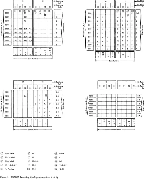
The 2540, as well as all System/360 configurations, uses the EBCDI code (Extended Binary Codc~d Decimal Interchange code) for all operations in data-mode 1 (Figure 1). Information processed in data-mode 1 is checked for validity according to the rule, "Any com-bination of punches in a single card column is valid
if it contains no more than one punch in rows 1-7.
I'
Reading
The 2540 read operation requires three machine cycles. During the first cycle, the card moves from the hopper to the read-check station (Figure 2). During the second cycle, the card passes through the readcheck station to the read station. During the -second cycle, the read-check brushes read the
IBM 2540 CARD READ PUNCH
punches in the card and develop a hole count for each column. On the third cycle, the card passes through the read station to the pte-stacker station. Data read from the card during the third cycle enters the read buffer in the 2821, from where it will be passed to the channel in response to the next read instruction.
Also during the third cycle, a second hole count is developed by the read brushes for each column and compared to the hole count from the read-check sta-tion. Disagreement between the two counts results in a read-check.
Punching
The punch operation requires four machine cycles. During the first cycle, the card leaves the hopper and moves to the blank station (Figure 2). During the second cycle, the card moves past the blank station to the punch station.
Data from the punch buffer in the 2821 is punched into the card during the third cycle as the card moves row-by-row through the punch station, and a hole count of the data being punched is developed and stored for each column. During the fourth cycle, the card passes through the punch-check station, where the punch-check brushes read the card, and develop a second hole count for each column, com-paring it to the hole count from the punch station. After punch checking, the card passes into the stacker area.
Stacker Selection
Read-stacker selection on the 2540 can be specified with the card-read instruction, or selection can be delayed until the program can evaluate the informa-tion read from the card and determine the appropri-ate stacker. There is no time limit for specifying the stacker selection, except that the select command must be given before, or with, the next Read com-mand.
01 .Bit POlitionl 0,1
00
I
01 110 111Bit Positionl 2,3,
0000
0001
CD @ G) @ ® ® (J)
I®
OS SP &
·~iT
I---50S /
"- _ OQJO
.0 F5 2 _ _
'"
~- ~11c
0 ~OO
~ 0101 CD
~10 0111
1000
~ RES BYP PN
HT NL LF RS
LC BS fOB UC DEL lL PRE EOT
II
3 .s:.
~
_Ii
CE[D~~~
l - ' - - - - Z O n e P u n c h e l - - - I
~
01 Bit Positions0,1 . Bit Positions 00 01 10 11 2,3
1001
1010
.0
'"
1011..;
c 1100
:~
~ 1101 CD
1110
1111
~I
Qj) f .
-5M ¢ ! : 2-8
f
-S I 3-8
1
-<
.
% @'-8 \
1
-( )
-f--==~
+ ;
>
; 6-81
-I ---, ? 7-8
"
-ITITJI"J"loJI
I ,
.
Zone Punchel II
CD
12-0- 1-8-9 @ 12 @ 0-2-8®
12- 1 1- 1-8-9 (2) 11 @°
ill 11-0-1-8-9
®
12-11-0 @ 0-1@ 12- 11-0-1-8-9 ® 12-0 @ 11-0- 1-9
® No Punches @ 11-0 @ 12- 11
Figure 1. EBCDIC Punching Configurations (Part 1 of 2)
"-..0
'"
~. !!! ,~ ~ CD 0000 0001 0010 0011 0100 0101 0110 0111 1000 1001 \ 1010~
1011 ~ 1100:~
( 1101 ~~ 1110
""
10 11
00 01 1O
"
00 01 10"
® @ @ @
°
~
a i A J I
b k I B K S 2
c I t C L T 3
d m u 0 M U
..
e n v E N V 5
f a w F 0 W 6
9 P )( G P X 7
h q y H Q Y 8
i r z I R Z 9
12 12
:1
II
"I
I
I
I
"
11 11°
°
°
I
~,---
Zone Punches---~1 - 0 1 , - - - Z o n e Punchel---!
Bit Positions 0,1 Bit Positionl
2,3 ...--~ 1 f---2 f---3 1 f--- u
..
c ).2f---5 'm
0 f---6 I---7 f---8
f
-9
I...---Bit POlitions 0, I Bit Positions
2,3
'-8l
::
)~
6-8
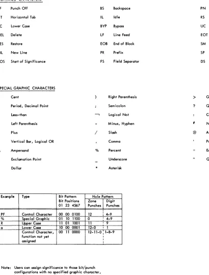
[image:6.617.55.554.59.700.2]CONTROL CHARACTERS
PF Punch Off BS Backspace PN Punch On
HT Horizontal Tab IL Idle RS Reader Stop
LC Lower Case BYP Bypass UC Upper Case
DEL. Delete LF Line Feed EaT End of Transmission
RES Restore EOB End of Block SM Set Mode
NL New Line PR Prefix SP Space
SOS Start of Significance FS Field Separator DS Digit Select
SPECIAL GRAPHIC CHARACTERS
¢ Cent Right Parenthesis
>
Greater- thanPeriod, Decimal Point Semicolon ? Question Mark
< Less-than
-,
Logical Not ColonLeft Parenthesis Minus, Hyphen
,
Number+
&
$
Plus / Slash
Vertical Bar, Logical OR Comma
Ampersand 0/0 Percent
Exclamation Point Underscore
Dollar * Asterisk
Example Type Bit Pattern Hole Pattern
Bit Positions Zone
I
Digit01 23 4567 Punches Punches
I
PF Control Character 00 00 0100 12 : 4-9
% Special Graphic 01 10 1100 0 I 4-9
R Upper Case 11 01 1001 11 I 9
a Lower Case 10 00 0001 12-0 I 1
Control Character, 00 11 0000 12-11-0 I 1-8-9
function not yet I
assigned I I
Note: Users can assign significance to those bit/punch configurations with no specified graphic character, but such assignments will not be supported by IBM.
Figure 1. EBCDIC Punching Configurations (Part 2 of 2)
Punch-stacker selection must be specified with the punch instruction. In 1400 Compatibility opera-tions, however, the stacker selection in a punch in-struction can be used to stack the card punched by
@ At
Prime, Apostrophe
Equal
Quotation Mark
the previous punch instruction.
[image:7.613.69.479.63.601.2]Punch Hopper
Punch Sta1'ion
Punch Check Station
Pre- Stacker Station
Read Check Station
Read Hopper
Blank Station (PFR brushes
installed here)
uuuuu
_1=
P1 P2
Figure 2. Card Paths
SPECIAL FEATURES
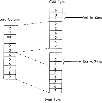
Data-Mode 2
The Column-Binary special feature on the 2821 per-mits the 2540 to read and punch records in data-mode 2 (column-binary coding). Each of the 80 card columns can contain two characters in data-mode 2. The upper six positions in each column are assigned to an odd-numbered storage byte; the lower six positions are assigned to the next higher even-num-bered byte (Figure 3). Because each character has just six bits, POSitiOlllS 0 and 1 of each 8-bit byte processed in data-mode 2 are set to zero.
Any combination of punches in a single column is valid in data-mode 2; validity checking in the 2540 read feed is suspended during data-mode 2 operation. Hole-count checking in both feeds is maintained.
Punch Feed Read
The PFR (Punch-Feed-Read) special feature consists of a set of 80 reading brushes installed in the blank station in the 2540 ptmch feed (see Figure 2). With PFR, the 2540 can process prepunched cards in the punch feed. Prepunehed data is read, and can be sent to the processing unit; new information can be punched into the cards after they have been read. If
the cards in the punch feed are not prepunched, the normal punch instruetions can be used. If the cards are prepunched, the PFR instructions must be used, or punch-check errors will result.
Reading and punching in the punch feed are simul-taneous: as data leaves the punch buffer and is punched row-by-row at the ptmch station, it is replaced by
RP3 R2 R1 Read Station
data from the card at the punch-feed-read station. Because the data being read from the punch feed enters the punch buffer, separate files of cards can be read simultaneously, one file in each feed, by the 2540.
A hole count is developed for each column read at the punch feed-read station. To this count is added the hole count from the data punched into the card at the punch station, and the total count is verified at the punch-check station. For this reason, punching in prepunched columns is permissible with PFR, but such punching cannot repeat the prepunch-ing. For example, punching an X-punch in a column that already contains a 2-punch is allowed; punching the letter K (X and 2 punches) into that column would repeat the 2-punch and would therefore cause a punch-check error.
Card Column
12 11
00
1 2
3
-4 5 6 7 8 9
Odd Byte
P
o
1 2 3 4 5 6 7 Po
1 2 3 4 5 6 7Even Byte
t---
Set to Zerot---
Set to Zero [image:8.612.40.563.49.217.2] [image:8.612.319.520.478.682.2]51-·Column Interchangeable Read Feed
The 51-Column Interchangeable Read Feed special feature makes possible the reading of either 80-column or 51-column cards by the 2540. The read hopper, the file-feed magazine, and stackers R1 and R2 are modified to permit the processing of either type of card; the capacities of these two stackers are reduced to approximately 800 cards, and maximum reading speed is reduced to 800 cards per minute for both types.
To change the 2540 from 80-column to 51-column card reading, the operator must place a guide rail at each side of the file-feed magazine to center the shorter cards on the magazine tray. He must also install side plates in the hopper to position the cards in the center of the hopper, and adjust stackers R1 and R2 by pulling forward the card guides at the rear of the stackers, and swinging down the adjustable card-pivot levers.
Returning to 80-column operation requires that the preceding steps be reversed. It is also sound practice to run a few 80-column cards through the feed before beginning operation after changing from the 51-column setup to ensure that all changes have been made correctly. This can be accomplished by loading a few cards into the hopper, entering them into the transport by pressing the reader start key, and performing a non-process-runout (NPRO) opera-tion.
Because the 51-column cards are read in the center of the read feed, data from these cards enters positions 15-65 of the read buffer. Positions 1-14 of the buffer remain blank. At the programmer's op-tion, data from the full 80 positions in the buffer, with positions 66-80 also blank, can be sent to the channel for each full-card record, or the full card can be read by terminating the data transfer after position 65.
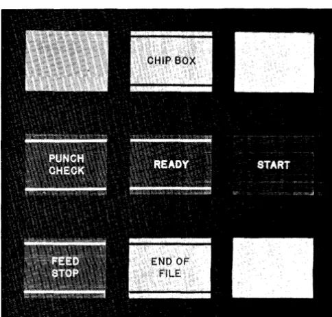
Figure 4. Reader Controls and Common Indicator Lights
OPERATOR CONTROLS
The 2540 operator controls are of three types: those affecting only the reader (Figure 4), those affecting only the punch (Figure 5), and those that reflect conditions common to both feeds (see Figure 4).
Reader Controls
Start Key
The reader start key has three functions:
1. Pressing the start key feeds cards to all stations in the read feed, enters the data from the first card into the read buffer in the 2821, and places the reader in Ready status if the read feed is clear of cards, hopper or the file-feed magazine contains cards, power is on, and all interlocks are satisfied.
2. Pressing the start key, when the hopper is empty, the reader end-of-file light is off, and the hopper joggler gate is open causes an NPRO of any cards in the read feed into stacker Rl.
3. Pressing the start key after clearing an error that required operator intervention, initiates any necessary feed cycles and places the reader in Ready status.
[image:9.615.330.572.454.685.2] [image:9.615.64.301.506.685.2]Stop Key
Pressing the reader stop key halts card movement at the completion of the current operation, turns off the reader end-of-file light, and places the reader in Not Ready status.
End-of-File Key
Pressing the reader end-of-file key conditions the 2540 so that card feeding and reading will continue, after the read hopper is empty, until the last card has been read and stacked.
Lights
As an aid to the programmer and the operator in planning restart methods, the following descriptions of error lights include the associated 2540 sense indications.
Feed Stop (Sense-Bit 1, Intervention Required) turned on when the reader motor is stopped by a card jam, a misfeed, a read clutch failure, or a failure to receive a signal from the 2821 after a read cycle is completed. Fe,ed Stop is turned off by the NPRO key.
Read Check (Sense-Bit 3, Equipment Check) signals the detection of a hole-count check, a parity check, an addressing error, or a translate check in the 2821 read buffer. Read Check is turned off by the next cOIn.mand.
Ready indicates that the reader is in Ready status.
Validity Check (Sense-Bit 4, Data Check) indicates that an invalid punch configuration (more than one punch in rows 1-7 of a single column) has occurred in a read or PFR data-mode 1 operation. Validity Check is turned off by the next command.
End-of- File indicates that the end-of-file key has been pressed, and that the end-of-file circuits are active. The end-of-file light goes out and the circuits are deactivated if the stop key is pressed, or if the last card has been stacked and an additional feed instruction, or read and feed instruction, has been received by the reader.
Punch Controls
Start Key
The punch start key has three functions:
1. Pressing the punch start key feeds cards into the punch and blank stations if the punch feed is clear of cards, the hopper contains cards, power is on, and all interlocks are satisfied. If PFR is installed, the contents of the first card enter the punch buffer in the 2821. 2. Pressing the punch start key with the hopper
empty causes a NPRO of all cards in the
punch feed into stacker PI. If PFR is installed, the punch end-of-file light must be off for a NPRO operation.
3. Pressing the punch start key after an error condition requiring operator intervention has been cleared initiates any necessary feed cycles, and restores the punch feed to Ready status.
Stop Key
Pressing the punch stop key halts card movement at the completion of the current operation, and places the punch in Not Ready status. If PFR is installed, pressing the punch stop key turns off the punch end-of-file light.
End-of- File Key
The end-of-file key is installed in the punch feed when the 2540 is equipped with the PFR special feature. Pressing the punch end-of-file key causes the 2540 to continue feeding and processing cards after the punch hopper is empty until the last card is read and stacked. This key should not be pressed for jobs that do not issue the PFR Read com:mand for the last card of the file, because the 2540 will not punch the last record after the last card is read.
Lights
As an aid to the programmer and the operator in planning restart methods, the following descriptions of error lights include the associated 2540 sense indications.
Chips (Sense-Bit 1, Intervention Required) indicates that the chip box is either full, or improperly positioned.
Re~ indicates that the punch is in Ready status.
addressing error, or translate check in the 2821 buffer. Punch Check is also turned on if these errors occur during a PFR Read operation. This indication is reset by the next command.
Feed Stop (Sense-Bit 1, Intervention Required) is turned on when the punch motor is stopped by a card jam, a misfeed, or a punch-clutch failure.
Feed Stop is turned off by the NPRO key.
End-of- File (installed in the punch feed only when the 2540 is equipped with the special feature) PFR turns on when the punch end-of-file key has been pressed, activating the punch-feed end-of-file circuits. If the punch stop key is pressed, the punch end-of-file light will go out and the circuits will be deactivated.
Common Indicator Lights
Transport (Sense-Bit 1, Intervention Required) indicates a card jam in the transport area of the 2540. This light goes out when the jam is cleared and the covers are closed.
Power indicates that the 2540 is being supplied with dc power.
Stacker (Sense-Bit 1, Intervention Required) indicates that anyone of the five stackers is filled.
Fuse indicates that a signal fuse in the 2540 has blown. A blown fuse must be replaced by a fuse of the sam,e size. An IBM Customer Engineer should be notified whenever a fuse has blown, because this could indicate a malfunction in the 2540 circuitry.
OPERATING AND RESTART PROCEDURES
Initial Start
To begin operation with the 2540 reader:
1. Perform a NPRO operation by opening the joggler gate, emptying the hopper, and pressing the reader start key to ensure that no cards are left in the feed.
2. Load the desired cards into the hopper of the file-feed magazine, and close the joggler gate. Card decks less than one-inch thick should be placed directly in the hopper with the card weight; larger decks can be placed in the file-feed magazine.
3. Press the reader start key. To begin operation with the 2540 punch:
1. Perform a NPRO operation by emptying the hopper and pressing the punch start key.
2. Load the desired cards into the punch hopper. 3. Press the punch start key.
Restarts from Error Conditions
The 2540 uses the flexible System/360 command set; therefore, different external error conditions can each require different restart procedures, depending on whether the 2540 operation is reading, punching, or PFR. If the program provides some programmed message to indicate the 2540 sense conditions, (type-out, print(type-out, system console display, etc.) the operator can use this message to determine which specific restart procedure he should follow. To locate the error card for read-check and validity-check errors, the operator should be familiar with the type of processing used by the program: that is, whether the program is reading and stacking each card with a single command, or delaying the stacker selection until the data from the card is analyzed.
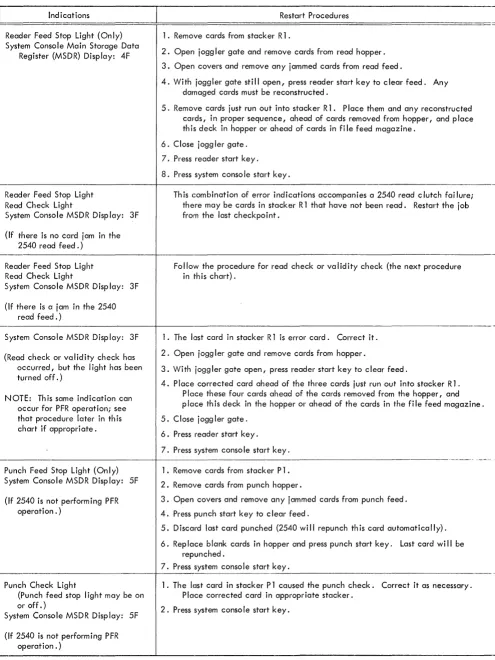
Figures 6 and 7 show the various 2540 error indications and appropriate restart procedures for standard operations, for PFR operations, and for 2540 Compatibility-mode operations. The procedures in Figure 7 assume that the I/O-Check-Stop switch on the system console is on. External indications and channel indications are included in both figures. The programmer should display the sense indications to the operator.
NOTE: The punch end-of-file key, installed as part of the 2540 Punch-Feed-Read special feature, should not be used when the 2540 is operating in 2540 Compatibility mode.
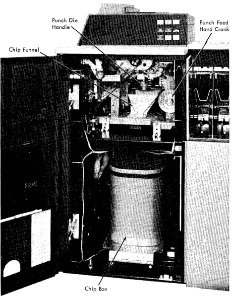
Jam Removal
The operator can gain access to the top of the read feed, transport and stacker area, and punch feed by raising the top covers of the 2540. He can remove the read-check brushes, the read brushes, the punch-check brushes, and the P FR brushes, as necessary, to free jammed cards (Figure 8).
If brushes must be removed, avoid contact be-tween the brushes and any other part of the machine. Such contact can damage the brushes or blow a fuse. When replacing these brushes, the locking pins should be snapped into place before a restart is attempted. A series of reader checks or punch checks upon restarting could indicate damaged or improperly positioned brushes.
Jams in the punch unit could require the operator to open the front cover of the punch feed, crank the punch clutch to a setting between 3350
3:nd 3500 ,
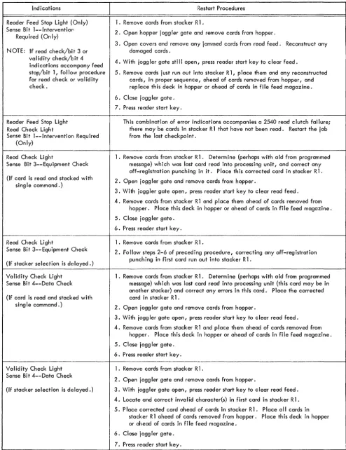
Indications
Reader Feed Stop Light (Only) Sense Bit 1--lnterventior:
Required (Only)
NOTE: If read check/bit 3 or validity check/bit 4 indications accompany feed stop/bit 1, follow procedure for read check or validity check.
Reader Feed Stop Light Read Check Light
Sense Bit 1--lntervention Required (Only)
Read Check Ligh·t
Sense Bit 3--Equipment Check
(If card is read and stacked with sing Ie command.)
Read Check Light
Sense Bit 3--Equipment Check
(If stacker selection is delayed.)
Validity Check Light Sense Bit 4--Data Check
(If card is read and stacked with sing Ie command.)
Validity Check Light Sense Bit 4--DOIta Check
(If stacker selection is delayed.)
Restart Procedures
1. Remove cards from stacker R 1 .
2. Open hopper j ogg ler gate and remove cards from hopper.
3. Open covers and remove any jammed cards from read feed. Reconstruct any damaged cards.
4. With joggler gate still open, press reader start key to clear feed.
5. Remove cards just run out into stacker R 1, place them and any reconstructed cards, in proper sequence, ahead of cards removed from hopper, and rep lace this deck in hopper or ahead of cards in file feed magazine.
6. Close jogg ler gate.
7. Press reader start key.
This combination of error indications accompanies a 2540 read clutch failure; there may be cards in stacker R 1 that have not been read. Restart the job from the last checkpoint.
1. Remove cards frorn stacker R 1. Determine (perhaps with aid from programmed message) which was last card read into processing unit, and correct any off-registration punching in it. Place this corrected card in stacker R1.
2. Open j ogg ler gate and remove cards from hopper.
3. With joggler gate open, press reader start key to clear read feed.
4. Remove cards from stacker R 1 and p lace them ahead of cards removed from hopper. Place this deck in hopper or ahead of cards in file feed magazine.
5. Close jogg ler gate.
6. Press reader start key.
1. Remove cards from stacker R 1 .
2. Fo 1I0w steps 2-6 of preceding procedure, correcting any off-reg istration punching in first card run out into stacker R 1.
1. Remove cards from stacker R 1. Determine (perhaps with aid from programmed message) which was last card read into processing unit (this card may be in another stacker) and correct any errors in this card. Place the corrected card in stacker R 1 .
2. Open jogg ler gate and remove cards from hopper.
3. With jogg ler gate open I press reader start key to c lear read feed.
4. Remove cards from stacker R 1 and p lace them ahead of cards removed from hopper. Place this deck in hopper or ahead of cards in file feed magazine.
5. Close jogg ler gate.
6. Press reader start key.
1. Remove cards from stacker R 1 .
2. Open jogg ler gate and remove cards from hopper.
3. With joggler gate open, press reader start key to c lear read feed.
4. Locate and correct inval id character(s) in first card in stacker R 1.
5. P lace corrected card ahead of cards in stacker R 1. P lace a II cards in stacker R 1 ahead of cards removed from hopper. Place this deck in hopper or ahead of cards in file feed magazine.
6. Close jogg ler gate.
7. Press reader start key.
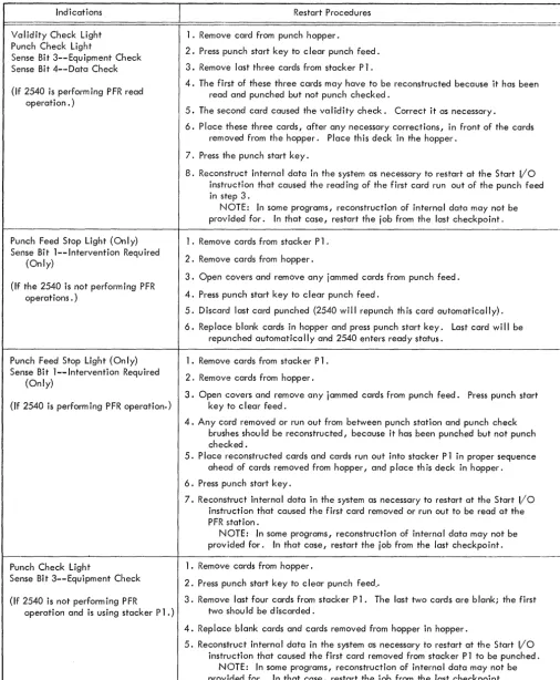
[image:12.615.45.540.56.699.2]Indications
Validity Check Light Punch Check Light
Sense Bit 3--Equipment Check Sense Bit 4--Data Check
(If 2540 is performing PFR read operation. )
Punch Feed Stop Light (Only) Sense Bit l--Intervention Required
(Only)
(If the 2540 is not performing PFR operations. )
Punch Feed Stop Light (Only) Sense Bit l--Intervention Required
(Only)
(If 2540 is perform ing P FR operation.)
Punch Check Light
Sense Bit 3--Equipment Check
(If 2540 is not performing PFR
operation and is using stacker Pl.)
Restart Procedures
1. Remove card from punch hopper.
2. Press punch start key to clear punch feed.
3. Remove last three cards from stacker Pl.
4. The first of these three cards may have to be reconstructed because it has been read and punched but not punch checked.
5. The second card caused the validity check. Correct it as necessary.
6. Place these three cards, after any necessary corrections, in front of the cards removed from the hopper. Place this deck in the hopper.
7. Press the punch start key.
8. Reconstruct internal data in the system as necessary to restart at the Start I/o instruction that caused the read ing of the first card run out of the punch feed in step 3.
I'-IOTE: In some programs, reconstruction of internal data may not be provided for. In that case, restart the job from the last checkpoint.
1. Remove cards from stacker Pl.
2. Remove cards from hopper.
3. Open covers and remove any jammed cards fr.om punch feed.
4. Press punch start key to clear punch feed.
5. Discard last card punched (2540 will repunch this card automatically).
6. Replace blank cards in hopper and press punch start key. Last card wi" be repunched automatica" y and 2540 enters ready status.
1. Remove cards from stacker Pl.
2. Remove cards from hopper.
3. Open covers and remove any jammed cards from punch feed. Press punch start key to c I ear feed.
4. Any card removed or run out from between punch station and punch check brushes shou Id be reconstructed, because it has been punched but not punch checked.
5. Place reconstructed cards and cards run out into stacker P 1 in proper sequence ahead of cards removed from hopper, and place th is deck in hopper.
6. Press p'Jnch start key.
7. Reconstruct internal data in the system as necessary to restart at the Start I/O instruction that caused the first card removed or run out to be read at the PFR station.
NOTE: In some programs, reconstruction of internal data may not be provided for. In that case, restart the job from the last checkpoint.
1. Remove cards from hopper.
2. Press punch start key to clear punch feed ..
3. Remove, last four cards from stacker Pl. The last two cards are blank; the first two should be discarded.
4. Replace blank cards and cards removed from hopper in hopper.
5. Reconst;ruct internal data in the system as necessary to restart at the Start I/O instruction that caused the first card removed from stacker P 1 to be punched.
NOTE: In some programs, reconstruction of internal data may not be provided for. In that case, restart the job from the last checkpoint.
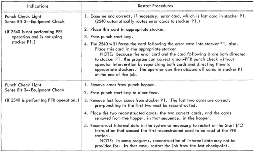
[image:13.618.60.566.62.676.2]Indications
Punch Check Light
Sense Bit 3--Equipment Check
(If 2540 is not performing PFR operation and is not using stacker Pl.)
Punch Check Light
Sense Bit 3--Equipment Check
(If 2540 is performing PFR operation.)
Restart Procedures
1. Exam ine and correct, if necessary, error card, wh ich is last card in stacker Pl. (2540 automatically routes error cards to stacker Pl.)
2. Place th is card in appropriate stacker.
3. Press punch start key.
4. The 2540 will force the card following the error card into stacker Pl, also. Place th is card in the appropriate stacker.
NOTE: Because the error card and the card following it are both directed to stacker P 1, the program can correct a non-PFR punch check without operator intervention by repunching both cards and directing them to appropriate stackers. The operator can then discard cill cards in stacker Pl at the end of the job.
1. Remove cards from punch hopper.
2. Press punch stclrt key to clear feed.
3. Remove last four cards from stacker Pl. The last two cards are correct; pre-punching in the first two must be reconstructed.
4. P lace the two reconstructed cards, the two correct cards, and the cards removed from the hopper, in that sequence, in the hopper.
5. Reconstruct internal data in the system as necessary to restart at the Start I/O instruction that caused the first reconstructed card to be read at the PFR station.
NOTE: In some programs, reconstruction of internal data may not be provided for. In that case, restart the job from the last checkpoint.
Figure 6. Restart Procedures - Standard and PFR Operation (Part 3 of 3)
handle clockwise until the lock at the top of the die is released, and, if necessary, trip the ejection trigger on the handle to remove the die from the machine.
[image:14.617.53.556.41.342.2]Indications
Reader Feed Stop Light (Only) System Console Main Storage Data
Register (MSDR) Display: 4F
Reader Feed Stop Light Read Check Light
System Console MSDR Display: 3F
(If there is no card jam in the 2540 read feed.)
Reader Feed Stop Light Read Check Light
System Console MSDR Display: 3F
(If there is a jam in the 2540 read feed.)
Restart Procedures
1. Remove cards from stacker R 1 .
2. Open joggler gate and remove cards from read hopper.
3. Open covers and remove any jammed cards from read feed.
4. With joggler gate still open, press reader start key to clear feed. Any damaged cards must be reconstructed.
5. Remove cards just run out into stacker R 1. Place them and any reconstructed cards, in proper sequence, ahead of cards removed from hopper, and place th is deck in hopper or ahead of cards in fi Ie feed magazine.
6. Close joggler gate.
7. Press reader start key.
8. Press system conso Ie start key.
Th is combination of error indications accompanies a 2540 read clutch fai lure; there may be cards in stacker R 1 that have not been read. Restart the job from the last checkpoint.
Follow the procedure for read check or validity check (the next procedure in 'this chart).
~---+---System Console MSDR Display: 3F
(Read check or validity check has occurred, but the light has been turned off.)
NOTE: Th is same indication can occur for PFR operation; see that procedure later in th is chart if appropriate.
1. The last card in stacker R 1 is error card. Correct it.
2. Open jogg ler gate and remove cards from hopper.
3. With joggler gate open, press reader start key to clear feed.
4. Place corrected card ahead of the three cards just run out into stacker R 1. Place these four cards ahead of the cards removed from the hopper, and place th is deck in the hopper or ahead of the cards in the fi Ie feed magazine.
5. Close jogg ler gate.
6. Press reader start key.
7. Press system conso Ie start key.
~---+--- ---Punch Feed Stop Light (Only)
System Console MSDR Display: 5F
(If 2540 is not performing PFR operation. )
Punch Check Light
(Punch feed stop I ight may be on or off.)
System Console MSDR Display: 5F
(If 2540 is not performing PFR operation. )
1. Remove cards from stacker Pl.
2. Remove cards from punch hopper.
3. Open covers and remove any jammed cards from punch feed.
4. Press punch start key to c lear feed.
5. Discard last card punched (2540 wi II repunch th is card automatically).
6. Replace blank cards in hopper and press punch start key. Last card wi II be repunched.
7. Press system console start key.
--~---1. The last card in stacker P 1 caused the punch check. Correct it as necessary. Place corrected card in appropriate stacker.
2. Press system conso Ie start key.
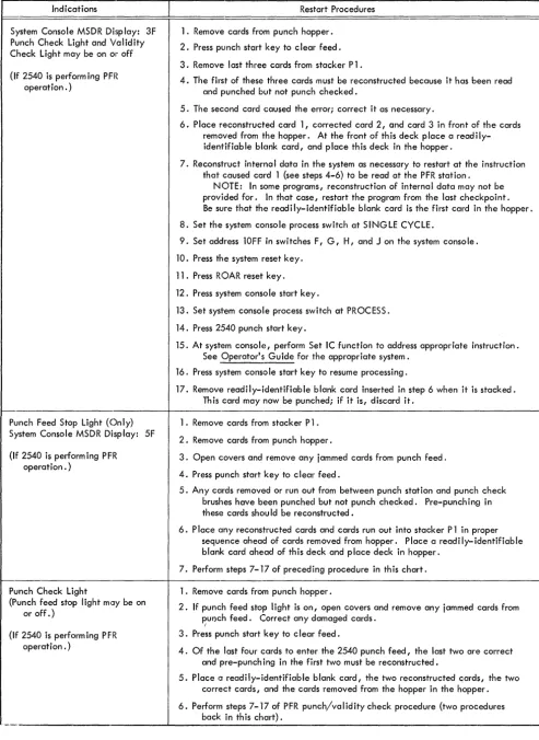
[image:15.613.69.564.36.696.2]Indications
System Console MSDR Di:)play: 3F Punch Check Light and Validity Check Light may be on Ol~ off
(If 2540 is perform ing PFR operation. )
Punch Feed Stop Light (Only) System Console MSDR Display: 5F
(If 2540 is performing PFR operation. )
Punch Check Light
(Punch feed stop light mlJy be on or off.)
(If 2540 is performing PFR operation. )
Restart Procedures
1. Remove cards from punch hopper.
2. Press punch start key to c lear feed.
3. Remove last three cards from stacker Pl.
4. The first of these three cards must be reconstructed because it has been read and punched but not punch checked.
5. The second card caused the error; correct it as necessary.
6. Place reconstructed card 1, corrected card 2, and card 3 in front of the cards removed from the hopper. At the front of th is deck p lace a read i Iy-identifiable blank card, and place this deck in the hopper.
7. Reconstruct interna I data in the system as necessary to restart at the instruction that caused card 1 (see steps 4-6) to be read at the PFR station.
NOTE: In some programs, reconstruction of internal data may not be provided for. In that case, restart the program from the last checkpoint. Be sure that the readily-identifiable blank card is the first card in the hopper.
8. Set the system console process switch at SINGLE CYCLE.
9. Set address lOFF in switches F, G, H, and J on the system console.
10. Press the system reset key.
11. Press R OAR reset key.
12. Press system console start key.
13. Set system console process switch at PROCESS.
14. Press 2540 punch start key.
15. At system console, perform Set IC function to address appropriate instruction. See Operator's Guide for the appropriate system.
16. Press system console start key to resume processing.
17. Remove readily-identifiable blank card inserted in step 6 when it is stacked. Th is card may now be punched; if it is, discard it.
1. Remove cards from stacker Pl.
2. Remove cards from punch hopper.
3. Open covers and remove any jammed cards from punch feed.
4. Press punch start key to c lear feed.
5. Any cards removed or run out from between punch station and punch check brushes have been punched but not punch checked. Pre-punching in these cards shou Id be reconstructed.
6. Place any reconstructed cards and cards run out into stacker P 1 in proper sequence ahead of cards removed from hopper. Place a readily-identifiable blank card ahead of this deck and place deck in hopper.
7. Perform steps 7-17 of preceding procedure in this chart.
1. Remove cards from punch hopper.
2. If punch feed stop light is on, open covers and remove any jammed cards from pUr)ch feed. Correct any damaged cards.
/
3. Press punch start key to c lear feed.
4. Of the last four cards to enter the 2540 punch feed, the last two are correct and pre-punch ing in the first two must be reconstructed.
5. Place a readily-identifiable blank card, the two reconstructed c:;:ards, the two correct cards, and the cards removed from the hopper in the hopper.
6. Perform steps 7- '17 of PFR punch/validity check procedure (two procedures back in this chart).
[image:16.618.46.540.36.713.2]Punch Check Brushes
Figure 8. Access to Transport
Figure 9. Access to Punch Feed
Reading
Brushes
Read
[image:17.612.68.580.38.298.2] [image:17.612.67.301.349.648.2]READER'S COMMENT FORM
IBM
2540 Component Description
and Operating Procedures
Form A21-9033-1
• Your comments, accompanied by answers to the following questions, help us produce better publications for your use .. If your answer to a question is "No" or requires qualification, please eXI?lain in the space provided below. Comments and suggestions become the property
of IBM.
• Does this publication meet your needs? • Did you find the material:
Easy to read and understand? Organized for convenient use? Complete?
Well illustrated?
Written for your technical level?
Yes
o
o
o
o
o
o
No
o
o
o
o
o
o
• What is your occupation? _ _ _ _ _ _ _ _ _ _ _ _ _ _ _ _ _ _ _ _ _ _ _ • How do you use this publication?
As an introduction to the subject?
0
For advanced knowledge of the subject?
0
For information about operating procedures?0
As an instructor in a class?
0
As a student in a class?0
As a reference manual?0
Other __________________________________________________ __• Please give specific page and line references with your comments when appropriate.
If you wish a reply, be sure to include your name and address.
A21-9033-1
fold
L
BUSINESS REPLY MAILNO POSTAGE NECESSARY IF MAILED IN THE UNITED STATES
, _ _ _- - - - J
Attention: Product Publications, Dept. 245
fold
JIrn~
<!lPOSTAGE WILL BE PAID BY •••
IBM Corporation
Systems Development Division Development Laboratory Rochester, Minnesota 55901
International Business Mal:hines Corporation Data Processing Division
FIRST' CLASS PERMIT NO. 387 ROCHESTER, MINN.
fold
A21-9033-1
ilrn~
®International Business Machines Corporation
Data Processing Division
K;
...
I
8
w
W
I