2016 International Congress on Computation Algorithms in Engineering (ICCAE 2016) ISBN: 978-1-60595-386-1
1 INTRODUCTION
Battlefield environment
Terrain Equipment … Special effect
Physical model
Reconnaissance model
Firing model
Maneuvering model
Intelligent model
Decision
Analytical judgment
[image:1.516.57.243.333.529.2]Regulation
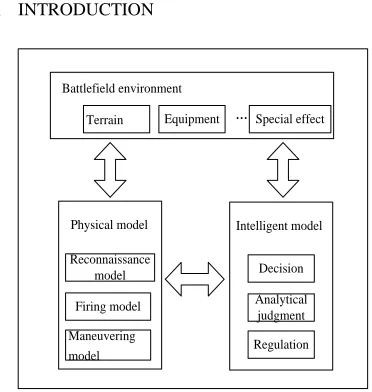
Figure 1. CGF model structure.
Computer Generated Forces (CGF) refers to simula-tion entities generated and controlled by computer in simulation battlefield environment. Manual control is not required for these entities. They are able to auto-matically give response to events in simulation battle-field environment which are the same as the actions taken in real battlefield. CGF has become important technical support for battle simulation and training simulation. As tank is important operation equipment for land force, the study of CGF lays the foundation to
establish battle simulation system for land force. Tank CGF contains various resolution ratios. For example, the attributes for CGF of a single tank, a tank platoon, or a tank battalion to focus on are completely different. CGF models with a high resolution ratio can be inte-grated into a high-level CGF model with a low resolu-tion ratio. CGF for single tank is the model with the highest resolution ratio in tank combat power. Estab-lished models which have been well improved with the highest fineness can be integrated into CGF mod-els for a tank platoon, a tank company, or even a higher-level tank combat unit according to certain algorithm. This paper has studied the main war power of single tank equipment and established a CGF model for single tank.
2 MODEL STRUCTURE
The organizational structure of CGF model requires good interoperability, reusability, and convenience to precisely describe the essential properties of modeling objects. According to the main functions of tank combat, we divide CGF model into four parts: ma-neuvering model, firepower model, reconnaissance model and intelligent model, among which maneu-vering model, firepower model and reconnaissance model belong to tank physical behavior model while the intelligent model belongs to human behavior mod-el. Intelligent model can obtain battlefield information according to the reconnaissance model in physical model, and it can make maneuvering decisions or
A CGF (Computer Generated Forces) Model for Single Tank
Lu Chen, Renyou Zhang & Bo Dong
Operational Experiment Center, Armored Force Academy, Bengbu, Anhui, China
ABSTRACT: A CGF (Computer Generated Forces) is the entity to simulate certain fighting equipment or unit in combat simulation system. A single tank CGF model is designed based on its fighting ability and characteristic. The model simulates not only the physical behaviors of mobility, fire, reconnaissance, but also the artificial be-haviors of decision. The mechanism of all the bebe-haviors is discussed, and the scientific and reasonable CGF model is constructed, which is validated by some warfare simulation systems.
decisions to use firepower based on various tactical regulations and analytical judgment, so as to achieve the interaction between two kinds of models.
Besides, tank CGF shall also accomplish the inter-action with battlefield environment, such as obtaining reconnaissance information, road information during maneuvering, and target information of firepower model. See Figure 1 for tank CGF model.
3 MANEUVERING MODEL
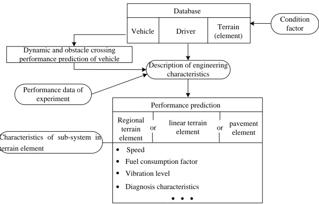
Maneuvering refers to vehicle passing ability and reachable running speed under certain terrain condi-tions. Maneuvering model describes the vehicle ma-neuverability. Theoretically, it can be a complete mathematical analysis model of which the input pa-rameters include pavement characteristics, vehicle performance and driver’s operation information while the output parameters include the highest running speed, barrier bypassing situation and fuel consump-tion of vehicle under certain terrain condiconsump-tions.
Pavement characteristics include the pavement na-ture and gradient. Based on methods of expressing complex terrain, pavement can be further divided into regional plot, segment plot and route. Terrain parame-ters within each plot, segment and route are presumed to be identical. This assumption is based on considera-tion for vehicle response sensitivity, actual measure-ment and convenience for experimeasure-mental calculation. It is accomplished by dividing each individual terrain factor into several differentials.
Vehicle performance mainly includes detailed de-scription of vehicle geometrical features, inertia fea-tures and mechanical properties. Performance module can include the calculation or measurement of ground
flatness, the dynamic response to obstacle crossing and bumping, and the requirements for ground clear-ance and traction during obstacle dispersing expressed by a series of parameters.
Driver information mainly refers to the driving ac-tions taken by driver, such as the operation input to gears, accelerator and joystick. In ideal situation, it can be regarded as the optimized driving actions taken by driver.
Detailed maneuvering model is constructed by a se-ries of vehicle running theose-ries. See Figure 2 for its basic composition and structure.
4 FIREPOWER MODEL
4.1 Exterior ballistic model
Ballistic trajectory simulation is a complex problem. Due to the influence brought by the initial velocity of projectile, the angular spin rate of projectile, the injec-tion angle of projectile, the quality, the shape and gravity of projectile, the air friction, the wind direction, the wind speed and bias, the flight path of shell pro-jectile in the air can be a very complex space curve. With the known initial velocity and sighting angle of gun (
0is obtained by looking up database accordingto target distance), the following differential equation of external ballistics can be resolved.
y x y y x x v dt dy v dt dx g v v G y CH dt dv v v G y CH dt dv / / ) ( ) ( / ) ( ) ( / (1)
Dynamic and obstacle crossing performance prediction of vehicle
Condition factor
Description of engineering characteristics
Performance data of experiment
Performance prediction
Regional terrain element
or linear terrain element
pavement element or Characteristics of sub-system in
terrain element
Database
Vehicle Driver Terrain (element) · · · Speed Diagnosis characteristics Vibration level Fuel consumption factor
·
· ·
[image:2.516.98.420.55.261.2]·
Where: Crefers to the elastic coefficient; H(y) refers to the air density function; G(v)refers to the resistance function. It is the function of velocity
v
and resistance law ( )0 a v
Gx with value expressed as
) ( 10 737 . 4 )
( 4 0
a v vG v
G x .
In initial conditions: t=0, x=0, y=0,
x x0 0 0
v = v = v cos(α ) , vy = vy0 = v sin(α )0 0 ( v0
refers to the initial velocity of gun and 0 refers to
the sighting angle of gun). With the known conditions, the above equation can be precisely resolved.
4.2 Projectile dispersion
Due to the influence of various random factors, pro-jectile may not be able to hit the target. In fact, the project dispersion obeys normal distribution. When CGF tank shoots target, points of impact will be in ellipse dispersion of the target center if it is the aiming point. Projectile dispersion distance and directional scattering follow normal distribution law. The disper-sion representations are respectively the distance probable error
d
G and the deflection probable error
f
G .
In analog computation of random disturbance of points of impact, the system error of tank gun shooting can be assumed as zero, and then the following steps can be taken to calculate random disturbance:
a. Use the pseudo-random number generators equally distributed by computer to generate two ran-dom numbers
1
and 2
on (0, 1).b. Set V12R11,V22R21, then V1 and V2
will be equally distributed within (−1, 1). Set
2 2 2 1
V
V
S
. If S1, we reject V1 and V2 and goto step ①; if S1, then there is a random point (V1, V2) within the shot plane.
c. Establishη = V -2lnS / S1 1 , η = V -2lnS / S2 2
then
1 and
2refer to the random numbers individ-ually obey the normal distribution N (0, 1).d. With the condition of already-known tank ball type and firing range, we look up firing table database to find direction probable errorGf, high-low probable
errorGg, fall anglec, and range probable error c
g
d G ctg
G .
e. Calculate random disturbance variables. X-direction random disturbance variable = deflec-tion probable error 4Gf×
1, and Y-direction randomdisturbance variable = range probable error 4Gd×
2.5 RECONNAISSANCE MODEL
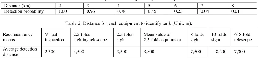
Reconnaissance of single tank is mainly accomplished by visual inspection and vehicle-mounted observation instrument inspection. Visual inspection is mainly realized by the description of target-finding probabil-ity. Under conditions with the same light environment, the probability of target detection by naked eyes be-comes lower in farther distance. Assume that the probability statistics of finding the target is shown in Figure 1, then whether the target will be detected in the model can be judged by looking up Table 1.
Through the observation completed by different visualizers, a statistical value of the distance to detect the target can be found. See Table 2 for the object distance (which is an assumed value and we assume that the tank of enemy can be found) in reconnais-sance accomplished by observation equipment.
The tests indicate that between the sights with dif-ferent amplification factors and visual observation, the following approximation relation can be found in the distance to identify (or find) the target:
D = Dm
W
1
(2) Where, Dm refers to the distance to find (or identify) the target by visual observation;D refers to the distance to find (or identify) the tar-get through some instrument;
W refers to the amplification factor of the instru-ment.
6 INTELLIGENT MODEL
[image:3.516.53.470.578.672.2]Intelligent model describes the perception, decision and implementation of tank on battlefield. The main purpose of establishing an intelligent model is to drive the physical tank controlled by computer in the system,
Table 1. Probability to find moving tank by visual inspection.
Distance (km) 2 3 4 5 6 7 8
Detection probability 1.00 0.96 0.78 0.45 0.23 0.04 0.01
Table 2. Distance for each equipment to identify tank (Unit: m).
Reconnaissance means
Visual inspection
2.5-folds sighting telescope
2.5-folds sight
Mean value of 2.5-folds equipment
8-folds sight
10-folds sight
6–8-folds telescope
Average detection
such as target tank or friendly neighbor. The intelli-gent model in this paper applies a gradational structure. It divides the structure into three structures according to the directions of information flow—the battlefield perception structure, the inferential decision structure and the mission planning structure.
As the interface of intelligent model, battlefield perception is in charge of obtaining and screening the abstract external environment information, analyzing the battlefield situation and judging the size of threat. The mission planning structure is in charge of plan-ning combat mission. It can divide problem planplan-ning into atomic tasks conforming to operational require-ments according to tactical regulations. The inferential decision structure can infer and analyze current prob-lems according to environment information, mission situation and related tactical regulations, decide its tactical operation and accomplish concrete functions by controlling physical model.
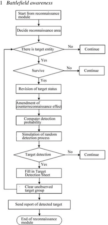
[image:4.516.61.243.268.648.2]6.1 Battlefield awareness
Figure 3. Reconnaissance flow chart of tank.
The entity battlefield perception of tank is mainly achieved by tank driver’s visual observation or by searching the range of observation with observation equipment. The observation results depend on search mode, range, environment, human factors, involved current state and target state.
Double-layer description method is used in sin-gle-tank search mode. See Figure 3 for the basic pro-cess of search.
6.2 Inference decision
There are many ways to make decisions, such as the inference based on regulations, the inference based on examples and the inference based on language envi-ronment. In intelligent area, the inference based on regulations has been wildly used. At present, many practical application systems can manifest stable per-formance with good effect. In addition, with quantity that is not huge, the single-vehicle operational regula-tion is relatively simple. Therefore, we are still using inference decision method based on regulations. The key of inference decision method based on regulations is to establish a knowledge base which is a group of decision rule collection for decision task completion.
The knowledge in the knowledge base refers to a rule with several condition attributes and one decision attribute. The rule can be expressed as follows:
If c(1)&c(2)&…&c(n) Then action
Where: The status condition is from c(1), c(2)…to c(n) while action refers to the behavior generated un-der the status.
See Table 3 for part of the detailed rule base. Table 3. Decision rule base.
Task Target Action
Search target A-type target Transit shooting
Search target B-type target Transit shooting
Search target C-type target Shooting
Search target D-type target Evasive action 1
6.3 Action planning
The action planning is to break up the actions gener-ated in tactical regulation decision into physical mod-ules which can complete several sub-actions individu-ally and transfer physical modules through control command. See Table 4 for action planning base.
The knowledge representations in action plan li-brary are as follows:
Action Sub-action (1) Value (1) …
[image:4.516.262.461.430.499.2]All sub-actions and sub-action names can corre-spond to the functional modules of physical modules. The implementation of sub-actions is accomplished by physical model.
7 REALIZATIONS AND APPLICATIONS
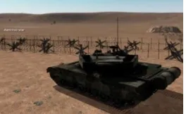
[image:5.516.54.465.67.420.2]The CGF for single tank established based on this paper can well describe the main behaviors and abili-ties of tank in real world which can satisfy the basic applications of various simulation training systems. Figure 4 shows the situation when a tank finds obsta-cles and bypass them. Figure 5 is the two-dimensional display of tank running route. According to Figure 5, the tank CGF designed from the model proposed in this paper can basically choose the marching route according to the principles of marching along the road and bypassing obstacles.
Figure 4. Bypassing barrier.
Figure 5. Route of self-motion march.
REFERENCES
[1] Guo, Q.S., Yang, L.G. & Yang D.P. 2006. Introductory Theory of Computer Generated Forces. Beijing: Nation-al Defense Industry Press.
[2] Sun, L.B., Liu, Y., Sun, J.Z. & Ni, H. 2010. Route Plan-ning Model Based on Mixed Perceptual Information.
Computer Engineering. 05.
[3] Tang, Z.J., Shi, S.Y. & Xue, Q.et al. 2013. Modeling and Simulation of the Process of Tank CGF Target Spotting.
Journal of System Simulation. 05.
[4] Li, G.H., Yang, L.G. & Guo, Q.S. et al. 2001. Simulation of the Maneuvering Characteristics of M1A2 Tank CGF System. Computer Simulation. 12.
Table 4. Action planning base.
Action Sub1 Sub2 Sub3 Sub4 Sub5 Sub6
Pass the minefield by following the signs. Start
March to counter point
March to counter point
March to counter point
Shock Start Speed up March to counter point
Stopping fire Stop shooting Start Acceleration March to counter point
Marching fire Speed cut Shooting Battlefield
observation Acceleration
Evasive action 1 Speed up Turn left Turn right Turn left Turn right March to counter point
Evasive action 2 Stop Start Acceleration March to counter point
Cover 1 March to
counter point Stop
Cover 2 March to
counter point Stop
Bypass to the right Turn right Bypass to march
March to counter point
Bypass to the left Turn left Bypass to march
[image:5.516.88.220.510.591.2]