2016 International Congress on Computation Algorithms in Engineering (ICCAE 2016) ISBN: 978-1-60595-386-1
1 INTRODUCTION
Numerical control technology is the basis of manu-facturing automation, flexibility, integrated production, and the essential means to improve product quality and labor productivity [1]. In the process of numerical control machining, numerical control programming is the foundation work, and programming by using CAD/CAM technology is widely used [2]. However, as the powerful manufacturing country, Japan can just conduct manual programming in implementation of numerical control skills identification, grading as-sessment and skills competition. CAD/CAM software is not allowed to be used for automatically program-ming, and programming macro program to conduct machining is the necessary occupational qualities for numerical control manufacturing personnel [3]. Macro program can directly manifest machining ideas of technologist, and the adjustment is flexible.
User macro program is the advanced form of nu-merical control programming [4], and the advantages
are very obvious corresponding to automatic pro-gramming by adopting CAD/CAM software. By adopting CAD/CAM to conduct programming, geo-metric modeling must be firstly conducted, and then program is generated [5]. The storage space demands toward machine tool are very large; however, the storage space of majority machine tool system not exceeds 256K. For the larger program, if machine tool DNC mode is adopted to machine, when computa-tional accuracy is high and feed speed F value is high-er, the transmission speed of program is unable to keep pace with the actual feed speed of machine tool, and the stagnation behavior of tool production appears to have a strong impact on product quality. However, the length of macro program is short, the response of system calculation is quick, and negative influence brought by transmission machining can be fully avoided [6]. In addition, machining precision of soft-ware programming is influenced by NC tool path cal-culation, CAD modeling calculation accuracy, inter-polation error, CAD drawing file conversion accuracy among different software and post-processing link, particularly extruding in high precision production [7].
Space Curved Surface Numerical Control Macro Program Milling
Programming and Simulation
Xiaoming Geng1* & Hongkang Wang2
1
Anhui Vocational College of Electronics & Information Technology, Bengbu, Anhui, China 2
Biochemical (Anhui) Co., Ltd., Bengbu, Anhui, China
ABSTRACT: In numerical control machining, the mode of automatic programming by CAD/CAM software for machine program has already been popularized. Relative to automatic programming, user macro program is the advanced form for numerical control programming, there are many advantages in the usage of production, but the degree of recognition in production is not very high, and the programming level macro program of employed person is not high. This article aims at FANUC numerical control system, analyzes the curved surface and the relevant equation from the perspective of analytic geometry, divides the commonly-used curved surface of nu-merical control milling, proposes programming ideas of macro program through case comparison, programs macro program corresponding to curved surface machining to conduct simulation of numeric control simulation tool path line, and simultaneously offers proposal for variable setting of macro program programming so as to reasonably program milling macro program in production according to the curved surface machining characteris-tic. Furthermore, this article also improves productivity on the premise of product quality assurance.
Keywords: space curved surface; mathematical model; numerical control milling; macro program; program-ming; simulation
Macro program is programmed in open type [8], all kinds of programming techniques can be used; pro-gram is concise, easy to understand and convenient to modify to reduce trial cut workload and labor intensity [9]
, and lessen influences of all kinds of errors in au-tomatic programming; the cycle of product design and machining is short, and production efficiency is obvi-ously improved. In production, CAD/CAM technique and user macro program shall mutually combine and learn from each other in mutual emulation. This article analyzes from the mathematical perspective and pro-poses strategy and ideas for programming of macro program aiming at the curved surface in FANUC nu-merical control system.
2 CURVED SURFACE MATHEMATICAL
DESCRIPTION
Space curved surface S is generally described through the zero set of three-dimensional function, that is:
( , , ) 3 ( , , )0
x y z R F x y z
S (1) 0 ) , , (x y z
F is the general equation for the curved surface S. If F is respectively the polynomial function and the transcendental function, the corresponding curved surface S is respectively called the algebraic surface and the transcendental surface. The degree of polynomial F(x,y,z) is called the degree of alge-braic surface. Analytic geometry studies linear and quadratic algebra curved surface, higher-degree alge-braic curved surface is the object of study for algebra-ic geometry, while the transcendental curved surface is the object of study for differential geometry [10].
Point
A
(
x
,
y
,
z
)
in the curved surface can be de-scribed through three binary functions, which are the parameter equation of the curved surface: ) , ( ) , ( ) , ( ) , , ( t s z z t s y y t s x x z y x
A (2)
Wherein the parameter
(
s
,
t
)
belongs to some area in plane, the image of function zf(x,y) is also a kind of special parameter equation.3 COMMON SPACE CURVED SURFACE
MACRO PROGRAMMING
3.1 The design of cylindrical surface machining macro programming
Cylindrical surface is the path surface formed by de-terminate curve in parallel translation along with
di-rectional straight line, or the path surface formed by directional straight line in parallel translation along with determinate curve [10]. As shown in Figure 1, the typical characteristic includes a determinate curve (generatrix or leading line) and a directional straight line (leading line or generatrix). The curve is quadratic space curve, and the space curve is generally de-scribed as the intersecting line of two space curved surfaces, the general equation can be expressed as
0 ) , , ( 0 ) , , ( z y x G z y x
F , the parameter equation can be
ex-pressed as ) ( ) ( ) ( t z z t y y t x x
(there is a variable parameter).
The parameter equation of the curved surface contains two variable parameters, composition of the curved surface shall be fully used in numerical control pro-gramming, namely a space curve and a straight line are used for writing numerical control macro program.
Figure 1. Cylindrical surface.
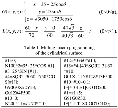
Case 1: Line segment L translates parallel to the ground along with the space curve G to form the cy-lindrical surface A, and programming of milling macro program for cylindrical surface A is tried to complete. Wherein G is the space non-circle curve intersected by spherical surface and cylindrical surface, and expres-sion formula of space curve G and line segment L are as follows: cos 1750 3050 sin 25 cos 25 35 : ) , , ( z y x z y x G (0≤θ≤π), t z y x z y x L 60 3 40 3 40 60 0 70 60 : ) , ,
[image:2.516.262.463.424.608.2]( (0≤t≤1).
Table 1. Milling macro programming of the cylindrical surface.
#1=0;
N100#2=35+25*COS[#1] ; #3=25*SIN [#1] ; #4=SQRT[3050-1750*CO S[#1]]; G90G0X#2Y#3; G01Z#4F500; #10=0; N200#11=#2-70*#10; #12=#3+60*#10; #13=#4-[40*SQRT[3]-60] *#10; G01X#11Y#12Z#13F500; #10=#10+0.1; IF[#10LE1]GOTO200; #1=#1+5; G91G0Z30; IF[#1LT180]GOTO100;
pro-gramming of line interpolation, and the last one is relevance of the two above programs to achieve varia-ble cycle control and complete linear description of the whole curved surface, that is to form machining tool path line.
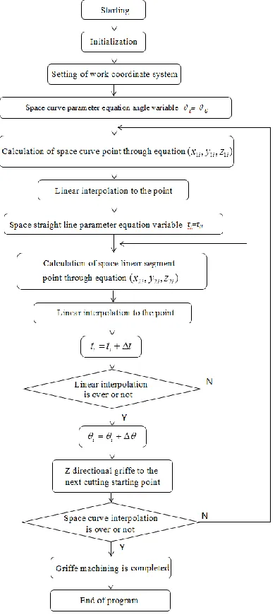
Figure 2. Programming logical relationship diagram of cylindrical surface macro program.
When programming, straight line program can be inserted into space curve program, starting point coor-dinate of the straight line is respectively generated through circulation calculation of space curve; curve program also can be inserted into straight line program, namely the space curve is used as the generatrix, and the straight line is used as the guide line to program.
[image:3.516.57.252.117.552.2] [image:3.516.294.432.157.248.2]The space curve is used as the guide line in the case, and the linear segment is translated to from the cylin-drical surface. In order to improve machining preci-sion, single-track mill is adopted in the program, namely griffe returns after completion of every cutting to feed again. Programming ideas of macro program are shown in Figure 2, macro program is shown in Table 1, and program tool path numerical control sim-ulation result is shown in Figure 3:
Figure 3. Cylindrical surface macro program run tool path.
3.2 The programming design of rotating curved surface machining macro program
[image:3.516.272.457.427.483.2]As shown in Figure 4, common rotating curved sur-face includes spherical sursur-face, rotating paraboloid and ellipsoid surface. Compared with cylindrical sur-face, the composition of rotating curved surface also includes two key factors, which are generatrix and rotation center line. Macro program is programmed by aiming at two geometric elements formed by curved surface, and then relevance is conducted to achieve variable cycle control and form machining tool path line.
Figure 4. Rotating curved surface.
Case 2: Known parabola 210 0 x
y (xmax 90), rotating paraboloid is formed by rotating around axle X (z is positive value), and writing of numerical con-trol milling macro program of the curved surface is tried to complete.
Analysis: Parabola rotates to form paraboloid, and then the paraboloid mathematical model is
) (
10 2 2
z y
parabolic equation is converted to parameter equation:
) 3 3 ( 10
102
t t y
t x
[image:4.516.55.252.117.618.2](3)
Table 2. Rotating paraboloid milling macro program.
#1=0;
N100#2=10*#1*#1; #3=10*#1; G01X#2Y#3F500; #10=0;
#11=#3;
N200 #12=#11*COS#10; #13=#11*SIN#10;
G01Y#12Z#13F500; #10=#10+2;
IF[#10LT180]GOTO200; #1=#1+0.1;
G91G0Z30; G90X#2Y#3; G01Z0;
IF[#1LT3]GOTO100;
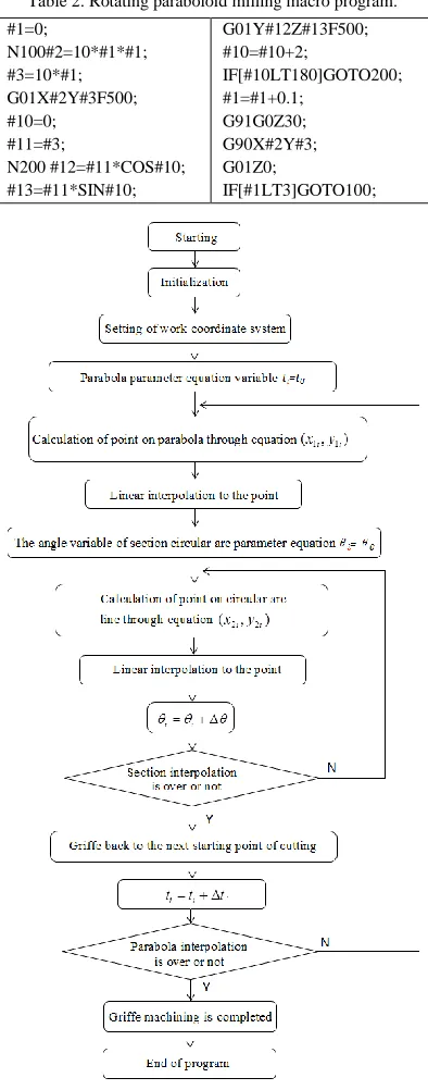
Figure 5. Rotating paraboloid milling macro program logic diagram.
Then the macro program is programmed according
to program logical relationship. Rotating paraboloid milling macro program logical structure is shown in Figure 5, tool path numerical control simulation path is as shown in Figure 6, and macro program is shown in Table 2.
[image:4.516.295.433.239.336.2]The case is programming of rotating curved surface; the guide line is parabola; section circular arc line segment is programmed by adopting parameter mode (circular interpolation instruction also can be used for programming); two lines are all quadratic curves so as to further generalize to the part surface of other similar structure, namely the macro program can be pro-grammed by adopting the mode for the curved surface formed by biquadratic curve. As shown in Figure 7, it is the internal surface tool path simulation path of a part, the guide line of the curve surface is an elliptical curve, and the section is another elliptical line.
[image:4.516.292.432.367.459.2]Figure 6. Simulation path of rotating paraboloid tool path
Figure 7. Programming tool path example of forming the curved surface by the biquadratic curve.
[image:4.516.263.444.500.568.2]3.3 Macro programming design of the guide line space curved surface of the double-section
Figure 8. The guide line curved surface of double-section.
type of curved surface can be called the guide line space curved surface of the double-section.
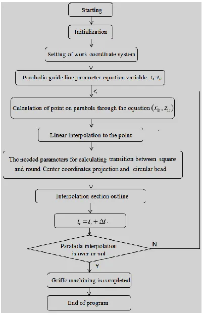
Figure 9. Upper square and lower round curved surface milling macro program logical structure.
Case 3: The known curved surface is formed by scanning of the upper section and the lower section along with a parabola, the upper section is a square with the length of each side of 60, the lower section is a round with the diameter of 120, and the height is 60. The parabolic equation is shown as follows:
) 60 0 ( 60
15 900
60
t t
z
t
x , the numerical
con-trol milling macro program of the curved surface is tried to program.
Analysis: For the guide line curved surface of the double-section, the key for programming is to estab-lish the rule of transition changes between two tions. One of the sections is used as the transition sec-tion of programming to program (for example, the square can be regarded as the graph with fillet radius for 0, and the round can be regarded as the square with the radius for R), and then mathematical relation be-tween relevant parameters is deduced, calculation is conducted according to the equation. Finally, macro program is completed according to the logical rela-tionship. In the case, the square with circular bead is
[image:5.516.265.468.232.458.2]used as the transition section to program, tool path is from top to bottom, mathematical correlation between the depth of cut and the size of circular bead is estab-lished, and the relevant parameters are calculated to program. In addition, scanning line is quadratic parab-ola and shall be completed in programming. For the similar structure curved surface, for example, the pat-tern is adopted by double-section and ellipse [11] to conduct programming. Figure 9 is curved surface milling macro program logical structure chart, tool path simulation path is shown in Figure 10, and macro program is shown in Table 3. The similar structure tool path is shown in Figure 11 with the scanning line in straight line.
Table 3. Upper square and lower round curved surface nu-merical control milling macro program.
#2=0;
WHILE[#2LE60]DO1; N100#20=
60-SQRT[15*[60-#2]]; #30=60-#2;
G01X#20 Z#30F500; #3=#20-[30-#2/2]; #4=30-#2/2; G1Y-[#20-#3]; G2X#4Y-[#20]I-#3;
G1X-#4;
G2X-[#20]Y-#4J#3; G1Y#4;
G2X-[#4]Y [#20]I#3; G1X#4;
G2X[#20]Y [#4]J-#3; G1Y0;
[image:5.516.282.440.498.602.2]#2=#2+3; END1;
Figure 10. Upper square and lower round parabola guide line curved surface macro program tool path.
3.4 Programming design of macro program of spherical surface
Spherical surface machining adopts the machining mode of hierarchy. Spherical surface is used as one type of rotating curved surface; the macro program is programmed not only according to programming de-sign ideas of rotating curved surface, but also by adopting spherical surface coordinate system; spheri-cal surface helispheri-cal line is used as tool path line to pro-gram; the program is more concise to effectively re-duce generation of tool marks on the cutting part.
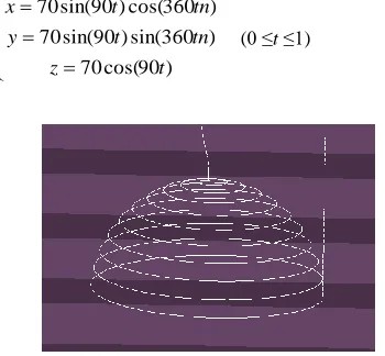
Case 4: Hemisphere is machined in the milling mode, the radius of sphere is 70mm, and numerical control machining macro programmed is tried to write.
Analysis: In spherical coordinate system, spherical point can be expressed as M(r,θ,ϕ) and can mutually
switch with rectangular coordinates cos sin sin cos sin r z r y r x ,
wherein r is the radius of sphere, θ is the included angle between vector quantityOMand axle Z, and ϕ is the included angle between vector quantityOM and axle X. Spherical surface helical line is deduced to generate on the basis of sine curve and Archimedes helical line, and the machined spherical surface can be used as cutting path line through spherical surface helical line. The helical line equation of the spherical surface in the case can be expressed as:
tn t r 360 90 70
(0 ≤t ≤1) (4)“90” is the latitude angle of hemisphere, n is the number of stitches of the helical line, and spherical coordinates are translated into rectangular coordinates executed by machine tool:
) 90 cos( 70 ) 360 sin( ) 90 sin( 70 ) 360 cos( ) 90 sin( 70 t z tn t y tn t x
[image:6.516.265.462.128.214.2](0 ≤t ≤1) (5)
Figure 12. Spherical machining tool path.
By using formula (5), the program can be finished. Spherical surface milling macro program is shown in Table 4, and machining tool path simulation path is shown in Figure 12.
Table 4. Macro program of machining spherical surface by adopting spherical helix.
#1=0; N100#10=90*#1; #20=360*#1; #30=10; #2=70*SIN#10*COS[36 0*#1*#30]; #3=70*SIN#10*SIN[360*# 1*#30]; #4=70*COS#10; G01X#2Y#3Z#4F500; #1=#1+0.002; IF[#1LT1]GOTO100;
3.5 The design of variable parameter
[image:6.516.265.462.451.593.2]When numerical control macro program is written, the key is to utilize variable to conduct cycle calculation. The variable parameter is equivalent change, such as variable control path line as the angle parameter and coefficient variable control cutter space, the generated tool path evenly changes, but the even tool path may influence the machining quality at times. As the spherical surface shown in Figure 12, there are differ-ent areas, such as flat area and steep area, even changes of tool path cannot entirely adapt all of the machining area, for example, increase of adjustable variable parameters, and the machining quality of the products can be improved. The variable can be used flexibly according to the physical truth. As listed in Table 5, in addition to equivalent setting variable, progressive increase or diminishing variable also can be used, or certain condition is set, and equal differ-ence of variable changes when meeting the conditions.
Table 5. Setting of variable.
Equivalence change
Progressive in-crease or dein-crease
Subsection changes #1=0; …… #1=#1+2; #1=0; #2=2; N20#1=#1+#2; …… N30#2=#2*0.9; IF[#1LT20]GOTO 20; #1=0; #2=2; WHILE[#1LE20] DO1; N10#1=#1+2; END1; …… WHILE[#1LE40] DO2; N30#1=#1+#2; …… N40#2=#2*0.9; END2; 4 CONCLUSION
[image:6.516.58.233.495.657.2]equation of the curved surface or the parameter equa-tion is established, the machining macro program can be written. Analysis of the curved surface of part can be divided according to the described cylindrical sur-face, rotating curved surface and one guide line of the double-section. In addition to the curved surface, plane, thread, drilling, chamfering and circular bead can be machined by writing macro program. The use of macro program in the production of machine tool can effectively guarantee the machining precision of products and improve the process quality of operating personnel, and the use of numerical control macro program shall draw enough attention.
REFERENCES
[1] Li Faxin. 2002. The design of numerical control ma-chining automatic programming system based on CAD/CAM. Xi’an: Northwestern Polytechnical Univer-sity.
[2] R. Soenen & G. J. Olling. 1995. Advanced CAD/CAM system: state-of-the-art and future trends in feature technology. Chapman & Hall on behalf of the Interna-tional Federation of Information Processing (IEIP). [3] Zhu Yuefeng. 2008. The study of numerical control
sys-tem macro program based on FANUC0i. Hefei: Hefei University of Technology.
[4] Zhang Fei. 2010. Research on automatic programming system for Mould-electrodes based on power mill. Guangzhou: Guangzhou University.
[5] Oberweis A, Pankratius V. & Stucky W. 2007. Product lines for digital information products. Information Sys-tems, 32(6): 909-939.
[6] Wang Fengbo & Sun Shibin. 2011. Application of FA-NUC system macro program to Parabola type parts. Coal mine machinery, 32(10): 148-150.
[7] R. R. Karinithi & D. Nau. 1992. An algebraic approach to feature interactions. IEEE Trans. Pattern Anal. Mach. intell, 14(2): 469-484.
[8] Fan Wei. 2014. Research on Interactive Programming system for virtual NC turning. Suzhou: Suzhou Univer-sity.
[9] Qiu Qin Yue & Hua Yu. 2011. Development and appli-cation of CNC turning macro-program based on non-circular curve. Applied Mechanics and Materials. 9 (105-107): 2271-2274.