University of Huddersfield Repository
Parkinson, Simon, Longstaff, Andrew P., Crampton, Andrew, Fletcher, Simon, Allen, Gary and
Myers, Alan
Representing the Process of Machine Tool Calibration in Firstorder Logic
Original Citation
Parkinson, Simon, Longstaff, Andrew P., Crampton, Andrew, Fletcher, Simon, Allen, Gary and
Myers, Alan (2011) Representing the Process of Machine Tool Calibration in Firstorder Logic. In:
Proceedings of the 17th International Conference on Automation & Computing. Chinese
Automation and Computing Society, Huddersfield, UK. ISBN 9781862180987
This version is available at http://eprints.hud.ac.uk/id/eprint/11499/
The University Repository is a digital collection of the research output of the
University, available on Open Access. Copyright and Moral Rights for the items
on this site are retained by the individual author and/or other copyright owners.
Users may access full items free of charge; copies of full text items generally
can be reproduced, displayed or performed and given to third parties in any
format or medium for personal research or study, educational or notforprofit
purposes without prior permission or charge, provided:
•
The authors, title and full bibliographic details is credited in any copy;
•
A hyperlink and/or URL is included for the original metadata page; and
•
The content is not changed in any way.
For more information, including our policy and submission procedure, please
contact the Repository Team at: [email protected].
Representing the Process of Machine Tool
Calibration in First-order Logic
S. Parkinson, A .P. Longstaff, A. Crampton, S. Fletcher, G. Allen, A. Myers
Centre for Precision Technologies, School of Computing & Engineering, University of Huddersfield, Queensgate, Huddersfield, HD1 3DH, UK
Abstract— Machine tool calibration requires a wide range of measurement techniques that can be carried out in many different sequences. Planning a machine tool calibration is typically performed by a subject expert with a great understanding of International standards and industrial best-practice guides. However, it is often the case that the planned sequence of measurements is not the optimal. Therefore, in an attempt to improve the process, intelligent computing methods can be designed for plan suggestion. As a starting point, this paper presents a way of converting expert knowledge into first-order logic that can be expressed in the PROLOG language. It then shows how queries can be executed against the logic to construct a knowledge-base of all the different measurements that can be performed during machine tool calibration.
Keywords-component; machine tool calibration; first-order logic; PROLOG
I. INTRODUCTION
The continuing desire to manufacture artefacts to a higher degree of accuracy while decreasing the production cost has resulted in the requirement for more accurate machine tools [1-3]. This is because excess error within a machine tool‟s capability will manifest to the artefact during machining, possibly resulting in out-of-tolerance parts that are scrapped or require re-work. By calibrating a machine tool, the asset owner can gain an understanding of the machine‟s capability.
In a perfect world, the machine would be able to move to predictable points in 3-dimensional space, resulting in a machined artefact that is geometrically identical to that of the designed part. It is, however, well known that the machining process contains many possible sources of error that make it extremely unlikely for the ideal case to prevail. Machine tool pseudo-static errors can be classified into three general classes of; (1) rigid-body geometric errors, (2) thermally induced errors, and (3) non-rigid errors [4-6]. Precalibrated compensation is the process of measuring the machine to establish the pseudo-static geometric errors that will be transferred to the workpiece during machining to implement corrective action. In practice a machine tool has considerably more dynamic and thermal error components, however, for the scope of this paper, consideration is only given to the pseudo-static geometric errors for a machine tool with three perpendicular linear axes.
Great effort has been spent by many to improve the process of machine tool measurement to correctly identify the machine‟s error components. International standards [7] and best-practice guides [8] provide guidance regarding the selection of test methods for individual error
components. These are critical for performing meaningful measurements on machine tools. However, even with this rich knowledge there is still a great deal of interpretation, selection and planning to be done to develop a good strategy for measuring a specific machine tool [9]. For example, ISO 230-2 [7] contains a section regarding test specification parameters that need to be “agreed” between the calibration supplier, manufacturer and the user. This results in the need for “independent” expert knowledge because often the user does not have the sufficient level of experience to make this decision and sometimes the interests of the manufacturer and user can conflict, leaving an expert to make the best decision to suit all. Furthermore, downtime for calibration is a cost to manufacturing, so optimising the workflow has distinct commercial advantages.
Computational intelligence potentially holds the key to allow for a more efficient method of planning machine tool calibration. The use of Artificial Intelligence (AI) in the form of knowledge-based planning can allow for the efficient searching of a very large search space. This could be beneficial for the process of machine tool calibration if the knowledge and decision-making skills of an experienced machine tool metrology expert can be interpreted in the form of a computer program.
In this paper a literature survey of the developments in dimensional metrology process planning is presented, followed by a discussion on the process of machine tool calibration to establish a basic set of requirements. The method of separating the requirements into first-order logic for the PROLOG language leading to the creation of a knowledge-base is described, followed by how to calculate the estimated time for performing the sequence of tasks in the knowledge-base. Finally, the paper concludes by laying out future plans for the complete implementation of an intelligent machine tool calibration process planner.
II. LITERATURE REVIEW
Within the subject of dimensional metrology, the effort required to create models and process guidelines are significant. However, it is common that the models are tailored for the measurement of specific, complex parts. Muelaner et al [10] presents a semi-autonomous method of metrology instrumentation selection for large-volume measurement based upon the artefact‟s dimensional criteria. This is performed by querying a database of known metrology instrumentation based upon the artefact‟s dimensions. However, the developed Proceedings of the 17th International Conference on
method is heavily dependent on user interpretation. For example, if the identified artefact was to contain several complex dimensional characteristics, the user would be required to identify and include each one within the query, followed then by checking for any instrument-related physical access and visibility obstructions. As a result, this method can only be used to aid the suggestion of instrumentation as human verification is always required. As briefly suggested by the author, an algorithm that was to automatically determine the artefact‟s dimensional characteristics and identify any physical access and visibility issues would be highly beneficial. This would allow for the model to be used with an increased degree-of-confidence and significantly reduce the need for human verification, therefore, saving time. A modification of this method would not be suitable for machine tool calibration because a more intelligent solution is required which will always attempt to find the optimal sequence of measurements.
Planning in AI terms is reasoning about the effects of actions and the sequencing of available actions to achieve a given cumulative effect [11]. The use of AI planning techniques has been explored in many subject areas, including manufacturing [12]. Large efforts are spent developing AI within robot control and improving their level of reasoning [13]. The developments in these areas are significant; however their application is vastly different from that of machine tool calibration. There is an absence of any literature indicating that implementing AI techniques within machine tool calibration has previously been attempted, even though the potential gains are significant.
III. CALIBRATION PLANNING
[image:3.595.338.506.465.736.2]To be successful at planning, it is essential to first comprehensively understand the problem in hand, the desired achievement, and the method of arriving there. Following this principle, the following section gives an overview of machine tool calibration.
Figure 1. Known and unknowns sections of machine tool calibration
Figure 1 illustrates the known and unknown aspects of machine tool calibration. To overcome the unknown aspect, a machine tool metrology expert is responsible for deriving a “plan-of-action” for measuring the machine‟s error components. To produce an autonomous method of planning, a method of defining the knowledge of a
machine tool calibration expert in first-order logic was discovered.
A. Expert’s knowledge
The knowledge and decision making procedure that a machine tool metrology expert possesses can be expressed as the following list of functions:
1. The ability to analyse the machine‟s configuration to derive a set of tests.
2. The ability to determine the possible/best equipment for each test.
3. The ability to determine the best order of tests.
These three areas of decision making are vast, so to create an effective program to perform the required functionality resulted in a detailed investigation to identify the components that can be represented in a logical structure suitable for programming.
B. Machine Configuration
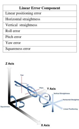
A machine can be constructed in many different ways to perform its task, and knowing the construction of the machine is essential for understanding the error components. These can be established because the geometric errors associated with both linear and rotary axes are known [1-5, 7, 14]. As shown in Table I, a linear axis will have six error components (six-degrees-of-freedom) plus a squareness error with the perpendicular axis. For the work presented in this paper, attention is only given to a machine tool with three perpendicular linear axes, which is illustrated in Figure 2.
Table I. Error Components
Linear Error Component Linear positioning error
Horizontal straightness Vertical straightness Roll error
Pitch error Yaw error Squareness error
[image:3.595.128.232.543.673.2]C. Possible Tests
Once the array of error components has been derived based upon the machine‟s constituent parts and their configuration, a method of measuring the error component is required. This is where the expert‟s opinion takes precedence. There is no definitive method of measuring an error component, only suggestions provided by ISO 230 [7] and industrial best practice guides [8]. The following list gives a very simplistic example of a test method that could be used to measure each of the seven error components.
1) Linear positioning error - Laser interferometry to compare the machine‟s reported position against the actual position.
2) Horizontal straightness - Laser interferometry to map the horizontal deviation.
3) Vertical straightness - Granite straight edge and dial test indicator to map the vertical deviation.
4) Roll error - Electronic level to record the angular roll deviation.
5) Pitch error - Electronic level to record the angular pitch deviation.
6) Yaw error - Laser interferometry to record the angular yaw deviation.
7) Squareness error - Using a metrological square and a dial test indicator.
As a starting point for creating a prototype model, a common set of parameters to distinguish a measurement must be established. These parameters are as follows:
1) Axis under test - Axis name
2) Maximum axis travel - Length in mm
3) Number of measurements - Quantity
4) Number of repeats - Quantity
5) Direction of travel - Positive, negative, bidirectional.
6) Accuracy - Quantity in the test‟s unit
7) Resolution - Quantity in the test‟s unit
8) Out of the box setup time - Quantity of time in minutes
9) Setup time by readjustment - Quantity of time in minutes
D. Best Order
As previously stated, the expert‟s execution of this method is different depending on their experience. Some individuals might prefer to perform the tests axis by axis, as some might prefer to perform the tests by the lowest effort of instrumentation setup. However, overall it is desirable for the most efficient method to be selected, which allows the calibration to be executed in the quickest time.
IV. CALIBRATION SYSTEM PLANNER
A. PROLOG
PROLOG is a programming language which is well suited to solving problems that involve objects and their relations [11, 15]. The work undertaken within this project could certainly be implemented in any procedural language; however, implementing symbolic computation by the use of PROLOG can considerably reduce the required quantity of code. For this reason, this work makes use of PROLOG language to produce a working prototype.
B. Relation Facts
Representing the information for performing a machine calibration in relation facts allows for dynamic processing. The relation facts can be regarded as the facts for the knowledge engine which would allow the planner to make intelligent decisions. For the prototype program, the following facts were used. The facts show the relationship in first-order logic for a machine tool with three perpendicular linear axes, which each have seven geometric errors that use different instrumentation for measurement. These facts lack a great quantity of information that is required to perform a machine tool calibration, but as an example to develop a working prototype, they are sufficient.
%%% Machine type and axis name
machine(three_axis_machine, x_axis). machine(three_axis_machine, y_axis). machine(three_axis_machine, z_axis).
%%% Axis name, type and travel
axis(x_axis, linear, 500). axis(y_axis, linear, 325). axis(z_axis, linear, 490).
%%% Axis type and error component
error(linear, position).
error(linear, horizontal_straightness). error(linear, vertical_straightness). error(linear, roll)
error(linear, pitch). error(linear, yaw). error(linear, squareness).
%%% Error component and measurement method
test(position, laser_interferometer).
test(horizontal_straightness, laser_interferometer). test(vertical_straightness, granite_stright_edge_dti). test(roll, electronic_level).
test(pitch, electronic_level). test(yaw, laser_interferometer).
test(squareness, metrological_square_dti).
%%% Measurement method, accuracy (μm), resolution (μm), setup time and adjust time.
Creating a PROLOG program with these facts allows us to essentially ask the program questions to retrieve useful knowledge. Consider the following prolog question;
Where: TY = Axis type, LEN = Axis travel length.
?- axis(x_axis, TY, LEN).
Here a query is being executed to return the axis type and axis travel by asking the following question; what is the type and travel for the axis „x_axis‟?
Executing this query would give us the response of;
Type (TY) = linear, Travel (LEN) = 500.
C. Knowledge
In the same way as asking the PROLOG program simple questions, complex questions can also be asked to acquire knowledge. For planning a machine tool calibration, it would be beneficial to know all the properties of the specified three axis machine, including each axis type, all the geometric error components per axis and a method of measuring them. Dynamically creating a knowledge-base at run time can be achieved by creating a PROLOG procedure. The following procedure creates a list of all the possible tests to be performed and then prints them out for the user to see. See TABLE II for a key to the variables.
knowledge_base(M):-
setof( [A, TY, E, I, AC, RE, ST, SA] , (machine(M, A), axis(A, TY, LEN), error(TY, E),
test(T, I), instrument(I, AC, RE, ST, SA)), List), print_kn(List).
print_kn([H|T]):-
write(H), nl, print_kn(T).
The following command initiates the procedure;
?- knowledge_base(three_axis_machine).
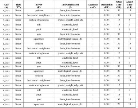
[image:5.595.75.525.423.775.2]PROLOG would interpret the supplied facts and try to answer the question in as many ways as possible. This will provide the required information regarding each of the possible axis, error, test and instrumentation relationships. The response for this query contains 21 sets of information (7 tests per linear axis). However, adding additional instrumentation and error facts would result in an increased knowledge base. Executing this query against the previously established facts will result in the output that can be seen in TABLE II. The produced knowledge-base is a list of all possible tests. Currently there is no intelligence to disregard and order the tests respective to the machine‟s configuration and available instrumentation.
TABLE II. KNOWLEDGE BASE OF ALL AVAILABLE TESTS
Axis (A)
Type (TY)
Error (E)
Instrumentation (I)
Accuracy (AC)
Resolution (RE)
Setup Time (ST)
Adjust Time (AT) x_axis linear position laser_interferometer 1 0.001 30 15 x_axis linear horizontal straightness laser_interferometer 1 0.001 30 15 x_axis linear vertical straightness granite_straight_edge_dti 1 0.001 15 8
x_axis linear roll electronic_level 1 0.001 18 9
x_axis linear pitch electronic_level 1 0.001 18 9
x_axis linear yaw laser_interferometer 1 0.001 30 15
x_axis linear squareness metrological_square_dti 1 0.001 20 15 y_axis linear position laser_interferometer 1 0.001 30 15
y_axis linear horizontal straightness laser_interferometer 1 0.001 30 15 y_axis linear vertical straightness granite_straight_edge_dti 1 0.001 15 8
y_axis linear roll electronic_level 1 0.001 18 9
y_axis linear pitch electronic_level 1 0.001 18 9
y_axis linear yaw laser_interferometer 1 0.001 30 15
y_axis linear squareness metrological_square_dti 1 0.001 20 15
z_axis linear position laser_interferometer 1 0.001 30 15 z_axis linear horizontal straightness laser_interferometer 1 0.001 30 15 z_axis linear vertical straightness granite_straight_edge_dti 1 0.001 15 8
z_axis linear roll electronic_level 1 0.001 18 9
z_axis linear pitch electronic_level 1 0.001 18 9
z_axis linear yaw laser_interferometer 1 0.001 30 15
D. Simple planner
1) Cost Calculator
A procedure which approximates overall cost in minutes for performing a machine tool calibration has been implemented. This procedure evaluates the potential cost of performing a measurement based upon the following six factors:
1. The time taken to set up the instrumentation out of the box.
2. The time taken to set up the instrumentation by readjustment.
3. The axis that the previous test was performed on.
4. The axis that the current test is being performed on.
5. The instrumentation used in the previous test.
6. The instrumentation used for the current test.
Implementing these six facts in PROLOG can be achieved with the following code:
Where: ST = Setup time, AT = Adjust time, PA = Previous axis, CA = Current axis, PI = Previous instrumentation, CI = Current instrumentation, COST = The overall cost in minute.
calccost(ST,AT,PA,CA,PI,CI,COST):- ( CA=PA ->
(CI=PI ->COST=AT ) ; COST=ST
);COST=ST.
Adding this procedure to the simple planner results in the additional output of the cost for each measurement. The result from this execution can be seen in TABLE III.
V. CONCLUSION AND FUTURE WORK
The work undertaken within this paper has described how to represent a simplified version of performing machine tool calibration by representing the parameters as logical facts in PROLOG, and then reasoning about those facts. This was done by breaking the calibration requirements down into first-order logic regarding the machine‟s axes, error components and the available instrumentation. Next PROLOG‟s ability to answer complex questions that provide a knowledge-base for further processing is shown. This resulted in the implantation of a method for calculating the cost of performing a sequence of measurements from the knowledge-base. This will serve as a baseline to compare a future intelligent implementation.
The implemented method allows for the
representation of an expert‟s knowledge that can subsequently be retrieved by anybody. However, because this method is based on simplified facts, it is not a complete solution that matches the real world scenario of machine tool calibration. The developed PROLOG program is a proof of concept which will lead to the implementation of a much more sophisticated and intelligent solution. The intelligent approach will require the creation of more facts and planning procedures to provide for a more complete application.
TABLE III. KNOWLEDGE OUTPUT INCLUDING CALCULATED COST
Cost Axis Type Error Component Instrumentation
30 x_axis linear position laser_interferometer
15 x_axis linear horizontal_straightness laser_interferometer
15 x_axis linear vertical_straightness granite_stright_edge_dti
18 x_axis linear roll electronic_level
9 x_axis linear pitch electronic_level
30 x_axis linear yaw laser_interferometer
20 x_axis linear squareness metrological_square_dti
30 y_axis linear position laser_interferometer
15 y_axis linear horizontal_straightness laser_interferometer
15 y_axis linear vertical_straightness granite_stright_edge_dti
18 y_axis linear roll electronic_level
9 y_axis linear pitch electronic_level
30 y_axis linear yaw laser_interferometer
20 y_axis linear squareness metrological_square_dti
30 z_axis linear position laser_interferometer
15 z_axis linear horizontal_straightness laser_interferometer
15 z_axis linear vertical_straightness granite_stright_edge_dti
18 z_axis linear roll electronic_level
9 z_axis linear pitch electronic_level
30 z_axis linear yaw laser_interferometer
20 z_axis linear squareness metrological_square_dti
VI. REFERENCES
[1] J. Mou, "A systematic approach to enhance machine tool accuracy for precision manufacturing,"
International Journal of Machine Tools and
Manufacture, vol. 37, pp. 669 - 685, 1997.
[2] R. W. Bagshaw and S. T. Newman, "Manufacturing data analysis of machine tool errors within a contemporary small manufacturing enterprise,"
International Journal of Machine Tools and
Manufacture, vol. 42, pp. 1065 - 1080, 2002.
[3] R. Ramesh, et al., "Error compensation in machine tools -- a review: Part I: geometric, cutting-force induced and fixture-dependent errors," International
Journal of Machine Tools and Manufacture, vol. 40,
pp. 1235 - 1256, 2000.
[4] D. G. Ford, et al., "The indentification of non-rigid errors in a vertical machining center," Proceedings of the Institution of Mechanical Engineers, Part B:
Journal of Engineering Manufacture, vol. 213, pp.
555-566, 1999.
[5] X. J. Wan, et al., "A unified framework of error evaluation and adjustment in machining,"
International Journal of Machine Tools and
Manufacture, vol. 48, pp. 1198 - 1210, 2008.
[6] S. Parkinson, et al., "A novel framework for establishing a machine tool quality metric," in Future
Technologies in Computing and Engineering
Proceedings of Computing and Engineering Annual
Researchers' Conference 2010 CEARC’10, G. Lucas
and Z. Xu, Eds., ed Huddersfield: University of Huddersfield, 2010.
[7] ISO230, "Part 1: Geometric accuracy of machines operating under no-load or finishing conditions," in
Test code for machine tools, ed. Geneva, Switzerland:
International Standards Organisation, 1996.
[8] NPL. (2005). Measurement Good Practice Guide No.
80.
[9] S. Parkinson, et al., "Controlling Machine Tool Accuracy Through a Robust Calibration Process," presented at the Yorkshire and North East Vitae Public Engagement Competition, Durham Town Hall, 2011. [10] J. E. Muelaner, et al., "Large Volume Metrology
Instrument Selection and Measurability Analysis,"
IMechE, 2010.
[11] I. Bratko, PROLOG Programming for Artifical
Intelligence, Third ed.: Pearson Education Limited,
2001.
[12] J. Madejski, "Survey of the agent-based approach to intelligent manufacturing," Journal of Achievements in
Materials and Manufacturing Engineering, vol. 21, pp.
67-70, 2007.
[13] G. Lim and I. Suh, "Robust robot knowledge instantiation for intelligent service robots," Intelligent
Service Robotics, vol. 3, pp. 115-123, 2010.
[14] H. Schwenke, et al., "Geometric error measurement and compensation of machines--An update," CIRP
Annals - Manufacturing Technology, vol. 57, pp. 660 -
675, 2008.