Oluwajobi, Akinjide O. and Chen, Xun
Modelling abrasive machining techniques using molecular dynamics
Original Citation
Oluwajobi, Akinjide O. and Chen, Xun (2008) Modelling abrasive machining techniques using
molecular dynamics. In: Proceedings of Computing and Engineering Annual Researchers'
Conference 2008: CEARC’08. University of Huddersfield, Huddersfield, pp. 100105. ISBN 9781
862180673
This version is available at http://eprints.hud.ac.uk/id/eprint/3688/
The University Repository is a digital collection of the research output of the
University, available on Open Access. Copyright and Moral Rights for the items
on this site are retained by the individual author and/or other copyright owners.
Users may access full items free of charge; copies of full text items generally
can be reproduced, displayed or performed and given to third parties in any
format or medium for personal research or study, educational or notforprofit
purposes without prior permission or charge, provided:
•
The authors, title and full bibliographic details is credited in any copy;
•
A hyperlink and/or URL is included for the original metadata page; and
•
The content is not changed in any way.
For more information, including our policy and submission procedure, please
contact the Repository Team at: [email protected].
MODELLING ABRASIVE MACHINING TECHNIQUES USING
MOLECULAR DYNAMICS
A.O. Oluwajobi and X. Chen
Centre for Precision Technologies, University of Huddersfield, Queensgate, Huddersfield HD1 3DH, UK
ABSTRACT
The development of ultra–precision processes which can achieve nanometre surface finishes and tolerances is now a critical requirement for many applications in medical, electronics and energy industry. Presently, it is very difficult to observe the diverse microscopic physical phenomena occurring in nanometric machining through experiments. The use Molecular Dynamics (MD) simulation has proved to be an effective tool for the prediction and the analysis of these processes at the nanometre scale. The complexity and the cost of experimental investigation have made this approach even more suitable as simulation results sometimes point interesting directions for experimentation. A review of the MD was undertaken, as this method can improve our understanding of nanometric processes and subsequently minimize experimental efforts.
Keywords abrasive machining, molecular dynamics, modelling
1 INTRODUCTION
Although abrasive machining is a century-old technology, it still plays an important role in industry today. In fact the need for high accuracy and high efficiency machining of difficult-to-machine materials is making the application of abrasive technologies increasingly important. Also, the abrasive machining has an advantage that the failure of one cutting edge doesn’t affect the process unlike other machining processes, because machining is performed with a large number of cutting edges (Inasaki et al 1993). Conventionally, the finite element method has been used to model processes and deformation at the macro and micro levels, but it was found to be difficult to apply to micromachining processes around 1nm (Inamura et al 1993). The MD can readily be used to solve such problems, as it is an effective microscopic approach for analysis from the atomistic viewpoint. The MD method was initiated in the late 1950s at Lawrence Radiation Laboratory in the US by Alder and Wainwright in the study of statistical mechanics (Alder and Wainwright 1959). Since then, the use of the simulation method has spread from Physics to Materials Science and now to Mechanical Engineering. In the field of nanometric cutting, Belak pioneered work on the study of cutting copper with a diamond tool (Belak and Stowers 1990). Initially, the method was used extensively to model indentation and cutting (see figures 1 and 2). In 1991, Belak and Stowers first applied the MD to abrasive processes (Belak and Stowers 1991) and Rentsch and Inasaki’s study later presented the first results of simulations targeted on the pile-up phenomenon in abrasive machining (Rentsch and Inasaki 1994). Relatively, not many studies have been carried out on abrasive machining, and this may likely be due to difficulties in developing suitable models in terms of the micro topography and in terms of the required potential functions for the material and interactions of interest. Also, MD studies have been restricted to single or few grits interfering with a work piece (Brinksmeier et al 2006). All these call for more studies on abrasive machining MD simulations.
2 THE MOLECULAR DYNAMICS METHOD
Molecular dynamics (MD) is a computer simulation technique used in the study of the motions of a set of particles – atoms. The technique works by following the time evolution of a set of interacting atoms while integrating their equations of motion. The method is based on statistical mechanics – a way to obtain a set of configurations distributed according to some statistical distribution function (Ercolessi 1997).
The simulation consists of the numerical, step-by-step, solution of the classical equations of motion. For a set of N atoms,
F
i=
m
ia
i (1)Where
m
i is the mass of atom i, 2 2dt
r
d
a
ii
=
, the acceleration of the atom i and is the force acting on atom i. (The forces are usually obtained as the gradient of a potential energy function, see equation 2).i
The outline of the MD simulation is as follows:
• Choose the model, choose an appropriate molecular potential and the means of calculating the equations of motion
• Initialize the model
• Relax the model from its initial state to its dynamically equilibrium condition • Run the simulation and analyze the results
2.1 Choose the model, choose an appropriate molecular potential and the means of calculating the equations of motion
The major task in a MD simulation is the selection of the potential. This is a function, of the
position of the nuclei which represents the potential energy of the system. Where
(
represents the complete co-ordinate position of the atoms. Then forces are derived from it as,)
,...
(
r
ir
NV
)
,...
Ni
r
r
(
i,...
.
N)
i
i
V
r
r
r
F
∂
∂
−
=
(2)Strictly speaking, the problem of modelling a material is that of finding a potential function for that material. If the potential function doesn’t model the behaviour of the atoms correctly, the results produced from the simulation would be wrong. As examples, the following are potentials and are adequate for the following materials – indicated below, viz; Lennard-Jones, Morse, Tersoff, Born-Meyer and Embedded-Atom potentials (Komanduri and Raff 2001).
Lennard-Jones Potential:
⎥
⎥
⎦
⎤
⎢
⎢
⎣
⎡
⎟
⎠
⎞
⎜
⎝
⎛
−
⎟
⎠
⎞
⎜
⎝
⎛
=
6 124
r
r
V
ijσ
σ
ε
(3)Where
σ
is a constant which is dependent on the physical properties of the material. This potential is suitable for rare gases (argon, krypton).Morse Potential:
V
ij=
D
{exp[
−
2
α
(
r
ij−
r
e)]
−
2
exp[
−
α
(
r
ij−
r
e]}
(4)Where,
ij
r
andr
e are instantaneous and equilibrium distances between atoms i and j respectivelyα
and D are constants determined on the basis of the physical properties of the materialThe Morse potential is suitable for cubic metals.
Tersoff Potential:
V
ij=
V
r(
r
ij)
−
B
ijV
a(
r
ij)
(5)Where
V
r andV
aare the potentials due to repulsive and attractive forces between atoms i and j andB
ijis a parameter that provides the information for the direction and the length of the bond. The Tersoff potential is used for covalently bonded materials like silicon atoms.Born-Meyer Potential:
Where A and
r
0 are constants dependent on the material. This potential is used for ceramics.Embedded-Atom Potential:
V
ij(
R
)
=
U
ij(
R
)
+
2
G
i'(
ρ
i)
ρ
aj(
R
)
+
G
i''(
ρ
i)(
ρ
aj(
R
))
2 (7)Where
U
ijis an electrostatic interaction between two atoms, G is the embedding energy,ρ
is a constant background density, is the average atomic electron density of atom and R is the separation of the atoms.The i and j depict the interacting atoms, and are the derivatives of G. The embedded-atom potential was developed for a wider range of metals. It incorporates an approximation for the many-atom interactions neglected by the pair-potential scheme.
a
ρ
'
G
G
''The list of the potentials is not exhaustive; and there are other potentials which are modified forms of the ones already discussed.
Generally, the most commonly used interaction model is the Lennard-Jones (LJ) pair potential. It is the standard potential to use for all the investigations where the focus is on the fundamental issues, and not studying the properties of a specific material.
After the choice of the potential, the next step is to select an appropriate algorithm for the integration of the equations of motion. This is the main kernel of the simulation program. The MD simulation is based on Newton’s second law of motion. The time integration algorithms for the solution of these equations are based on finite difference methods. It is important to note that this is so because the collisions between atoms are not instantaneous, but they are strong repulsive and attractive interactions that occur over a finite duration. Examples of these methods are Verlet and predictor-corrector algorithms.
The Verlet algorithm is of three types, namely; the basic (position) Verlet, the Verlet Leapfrog and the velocity Verlet algorithms. The basic Verlet algorithm uses two, third order Taylor expansions, and calculates the positions at the next time step from the positions at the previous and current time steps. The predictor-corrector algorithm, on the other hand consists of three steps. The first step is to predict (by Taylor expansion) positions and their time derivatives at time,
t
+
Δ
t
, from values known at a time t. The second step is to compute the force by taking the potential at the predicted positions, and comparing the resulting acceleration, with the predicted acceleration. The last step is to correct the positions and their derivatives by using the difference between the computed and the predicted acceleration (known as the error signal). The predictor-corrector algorithm gives more accurate results, but it is computationally expensive and requires large storage.2.2 Initialize the model
To initialize the simulation, the MD ‘box’ (the control volume) must be defined and initial positions and velocities of the atoms must be assigned – this is a kind of initial randomization.
Positions of the atoms can be defined, by assuming certain crystal structure and the initial velocities can be randomly assigned.
2.3 Relax the model from its initial state to its dynamically equilibrium condition
The model of having atoms positioned and assigned velocities as above implies that additional potential energy between atoms has been artificially applied to the system. This is not the case in real solids, where atoms are actually vibrating around their equilibrium positions. So, it is necessary to relax this initial model from its artificially assigned initial conditions to its natural, dynamically equilibrium condition.
2.4 Run the simulation and analyze the results
3 EXAMPLES OF MD SIMULATION OF ABRASIVE MACHINING
(Rentsch and Inasaki 1994) modelled a copper work material and a diamond tool for their study. They used the Lennard-Jones potential function for the copper atom interactions, but kept the boundaries and the tool stiff. A total of 11476 atoms in 13 horizontal (1,1,1) – layers of fcc-lattice were used for the copper, and the tool was shaped from a diamond lattice block by clearing on the four (1,1,1) –planes. Using a cutting speed of 100m/s, they observed a pronounced build-up phenomenon after 25000 time steps (see figure 3).
The MD simulation of nanometric cutting was carried out with a range of negative-rake tools to simulate the Ultra-Precision Grinding (UPG) process by (Komanduri et al 1999). A copper work material and an infinitely hard tool (tungsten) were used in the simulations. A pairwise sum of Morse potential was used for the study, in which they concluded that simulation tests can facilitate a better understanding of the process without the need for expensive and time consuming machining or grinding experimental work.
The investigation of the fundamental atomistic processes in chemical mechanical polishing of copper was carried out by (Ye et al 2002). They simulated the nanoscale polishing of a copper surface by a single abrasive particle, using the embedded atom method potential. They focused on the mechanical abrasion aspect of material removal and found that dislocations and atomically rough planarized surface were formed.
(Lin et al 2003) used the MD method to survey the features of grinding energy dissipation, grinding stress, strain state and grinding temperature in the atomic space. The workpiece and the tool materials were assumed to be monocrystalline silicon with a covalent bond and diamond respectively. A Tersoff potential function, suited to a multibody system was employed for the simulation. They found out that as the abrasive grain cut into the workpiece continuously, the value of the grinding force increased gradually in a repeated fluctuation manner. Also, it was observed that atoms of the crystal lattice were reconstituted and parts of the non-crystal atoms were piled up on the front of the abrasive grain.
To be more realistic, (Rentsch and Inasaki 2006) extended the state-of-the-art MD material modelling to consider fluids like coolants. They considered the impact of such fluids on the surface generation and the tribological contact conditions. The fluid-fluid interactions were calculated on the basis of the Lennard-Jones potential function and the embedded potential function was used for the inner workpiece reactions (the internal tool dynamics were ignored). They observed an intensive self-diffusion of the fulid atoms, and these filled the whole free space above the workpiece. No impact on the stress distribution was observed, but the whole fluid-tool/workpiece contact was heated up in a narrow range.
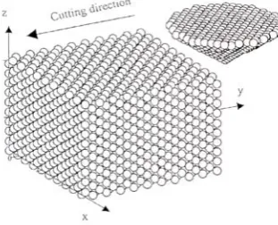
Rentsch and Brinksmeimier obtained a 3-D MD simulation of the grinding process (Brinksmeier et al 2006). Using the embedded atom method potential and 100000 atoms, they modelled two abrasives that cut through a workpiece over its whole length at 100m/s (see figure 4).They found that the periodic borders in the horizontal plane led to complete groove formation in the cutting direction.
The MD simulations of nanoindentation followed by scratching at constant depth on the Si-terminated (0 0 1) surface of 3CSic was carried out by (Noreyan and Amar 2008). They investigated the dependence of the friction coefficient, scratch hardness, and wear on scratching depth, velocity, direction, and indenter size and shape. The workpiece was assumed to have the 3C SiC cubic crystal structure, and a diamond tip was used. Both were modelled using the Tersoff potential. They found that the friction coefficient and the scratch hardness increased with indentation depth but decreased with increasing scratching velocity. They also noted that the direction dependence of the friction coefficient is weaker at high scratching velocity.
In most of the MD simulations, the representation of the abrasives have been simplified to a block, pyramid, or shell of stiff atoms with sharp or rounded edges that have no dynamics themselves (Brinksmeier et al 2006). There is need for more studies on the dynamics within the abrasives.
4 CONCLUSION
5 REFERENCES
ALDER B.J.and T.E. WAINWRIGHT (1959),’Studies in Molecular Dynamics. I. General Method’, Journal of Chemical Physics, Vol 31 pp 459-466
BELAK, J. and STOWERS, I. F. (1990), ‘A Molecular Dynamics Model of the Orthogonal Cutting Process’, Proceedings of the American Society of Precision Engineering pp 76-79.
BELAK, J. and STOWERS, I. F. (1991),’The Indentation and Scratching of a Metal Surface: A Molecular Dynamics Study’, Fundamentals of Friction: Macroscopic and Microscopic, Singer, Pollock E 220 pp 1-10
BRINKSMEIER E., J. C. AURICH, E. GOVEKAR, C. HEINZEL, H.-W. HOFFMEISTER, F. KLOCKE, J. PETERS, R. RENTSCH, D. J. STEPHENSON, E. UHLMANN, K. WEINERT and M. WITTMANN (2006), ‘Advances in Modelling and Simulation of Grinding Processes’, Annals of the CIRP Vol. 55, No 2,
pp 667-696
ERCOLESSI F. (1997), ‘A Molecular Dynamics Primer’, Spring College in Computational Physics, ICTP, Trieste, June 1997. http://www.fisica.uniud.it/~ercolessi/md/md/ (Accessed in 2008)
FANG T. and C WENG (2000),’Three-Dimensional Molecular Dynamics Analysis of Processing using a Pin Tool on the Atomic Scale’, Nanotechnology Vol 11 pp 148-153
INAMURA T., N. TAKEZAWA and Y. KUMAKI (1993), ’Mechanics and Energy Dissipation in Nanoscale Cutting’, Annals of the CIRP Vol. 42, No 1, pp 79-82
INASAKI I., H.K. TONSHOFF and T.D. HOWES (1993),’Abrasive Machining in the Future’, Annals of the CIRP Vol. 42, No 2, pp 723-732
KOMANDURI R., N. CHANDRASEKARAN and L.M. RAFF (1999),’Some Aspects of Machining with Negative-Rake Tools Simulating Grinding: A Molecular Dynamics Simulation Approach’, Philosophical Magazine Part B, Vol. 79 No 7, pp 955-968
KOMANDURI R., and L.M. RAFF (2001),’A Review on the Molecular Dynamics Simulation of Machining at the Atomic Scale’, Proceedings of the Institution of Mechanical Engineers
Vol 215 Part B pp 1639-1672
LIN B., S.Y. YU and S.X. WANG (2003),’An Experimental Study on Molecular Dynamics Simulation in Nanometer Grinding’, Journal of Materials Processing Technology Vol 138 pp 484-488
LUO X. and K. CHENG (2004),’Abrasive Nanometric Machining: Modelling, Simulation and its Application Promise’, Key Engineering Materials Vols 257-258 pp 27-32
NOREYAN A. and J.G. AMAR (2008),’Molecular Dynamics Simulations of Nanoscratching of 3C SiC ‘, Wear pp 956-962
RENTCH R. and I. INASAKI (1994),’Molecular Dynamics Simulation for Abrasive Processes’, Annals of the CIRP Vol. 43, No 1, pp 327-330
RENTCH R. and I. INASAKI (2006),’Effects of Fluids on the Surface Generation in Material Removal Processes’, Annals of the CIRP Vol. 55 No1, pp 1-4
Figure 1: Schematic of the MD Simulation of Nanometric Cutting (2D) (Komanduri and Raff 2001)
Figure 2: Schematic of the MD Simulation of Nanometric Cutting (3D)(Fang and Weng 2000)
Figure 3: Advanced MD Simulation with Straight Aligned Tool (Rentsch and Inasaki 1994)
[image:7.595.197.400.431.534.2] [image:7.595.194.405.581.743.2]