Journal of Chemical and Pharmaceutical Research, 2013, 5(9):522-528
Research Article
CODEN(USA) : JCPRC5
ISSN : 0975-7384
An attitude error correction method based on MARG sensor array
1
Mingjian Li,
2Chen Chen,
1*Ning Han and
1Fei Yan
1
School of Technology, Beijing Forestry University, Beijing, China
2
Department of Electrical Engineering, The University of Texas at Dallas, Richardson, TX
_____________________________________________________________________________________________
ABSTRACT
Applying EKF(extended Kalman filter) based integrated navigation to correct the measurement error of MEMS
(Micro-electromechanical Systems)suffers great computational load, slow convergence and implementation infeasibility. Based on steepest decent algorithm and complementary filter theory, this paper presents an attitude error correction method using MARG (Magnetic, Angular Rate, and Gravity) sensor array. This method uses the Jacobian matrix to substitute the recurrence formula of EKF, which significantly reduces the computational complexity. It only requires to tune two filter gains which are determined by the gyroscope measurement error leading to an ease of implementation. The experimental results of MARG/EKF simulation and MARG/turntable indicate that our proposed method has lower computational complexity and faster convergence than the EKF method. In addition, our proposed method can achieve high accuracy when MARG sensors are operated at low sampling rates, which is very desirable for applications constrained by low power consumption or limited processing resources.
Key words: MARG sensor array; steepest descent method; complementary filter; extended Kalman filter (EKF); attitude error correction
_____________________________________________________________________________________________
INTRODUCTION
The limited driving force and load capacity of micro air vehicles (MAVs) require a small, light weighted and low power consumption attitude measurement system. MEMS (Micro-electromechanical Systems) sensors have been widely used in miniature attitude system due to their small size, low cost, and low power consumption. However, noise and sensor drift can cause large attitude error in a short period of time when MEMS sensors are used alone.
In this paper, MARG (Magnetic, Angular Rate, and Gravity) sensor array consisting of MEMS three-axis gyroscope, accelerometer and magnetometer are used to capture three-dimensional acceleration, magnetic field and angular velocity. Based on steepest descent method and complimentary filter theory, we propose to use ground magnetic and gravity field observations to correct the attitude error of the gyroscope. Our proposed algorithm is denoted as MARG algorithm. To evaluate the performance of the proposed algorithm, we carry out gyro/accelerometer/ magnetometer integrated navigation simulation experiment and MARG/turntable experiment. Experimental results indicate superior performance of our method over the traditional Quaternion extended Kalman filter (QKF) method.
PROPOSED MARG LGORITHM
Attitude angle of the rotated carrier can be represented by rotation quaternion. The parameters of quaternion can be solved by minimizing the error function of quaternion. Steepest descent method is an ideal iterative algorithm for minimization which was first introduced by Cauchy in 1847. It can find the local minima of an objective function and is widely explored in engineering applications since it has the advantages of small workload, memory efficient and easy to implement [4]. The search path of the steepest descent method appears to be serrated. In the first a few steps, the objective function decreases rapidly. When it approaches the local minima, the convergence speed becomes slow. Usually steepest descent method is used with other techniques for fast convergence. Based on steepest decent algorithm and complementary filter theory, we propose an attitude error correction method by fusing information from different sensors. The block diagram of the proposed method is shown in Fig. 1.
Fig. 1: Block diagram of proposed method
The discrete function of body rotation quaternion and angular velocity can be expressed as
,
ˆ
, 1 ,,
b b b
n
q
w t
nq
est t
nq
w t
t
(1)where
t
is the sampling interval, nbq
w t, is the quaternion at timet
, nbq
w t, is the rate of change of quaternion.1 2 3 4
ˆ [ ]
b
nq q q q q is the rotation quaternion from navigation coordinate system n to body coordinate system b.
ˆ [0
]
n
x y z
d
d
d
d
and bs
ˆ [0
s
xs
ys
z]
represent the measurement of accelerometer and magnetometer in the navigation coordinate system and body coordinate system, respectively. The quaternion error function is defined as follows:*
ˆ
ˆ
ˆ
ˆ
ˆ
ˆ
ˆ
(
nb,
n,
b)
nb n nb b.
1
ˆ
ˆ
ˆ
(
,
, )
ˆ
,
0,1, 2...
ˆ
ˆ
ˆ
(
,
, )
b n b
b b n k
n k n k b n b n k
f
q
d s
q
q
k
n
f
q
d s
(3)ˆ
ˆ
ˆ
ˆ
ˆ
ˆ
ˆ
ˆ
(
nb k,
n, )
b T(
nb k,
n) (
nb k,
n, )
bf
q
d s
J
q
d f
q
d s
(4)Wherein
indicates step size, f indicates gradient of the objective function, andJ
is the Jacobian matrix. In the beginning, the carrier is in still state, the measurements of accelerometer and magnetometer areˆ [0 0 0 1]
n
g
and2 2
*
ˆ [0 0 ] [0 0 ]
ˆ
ˆ
ˆ
n
x z x y z
b b b
n n
b b b h h h
q
m
q
, respectively. After some arbitrarychanges in attitude, the measurements become b
a
ˆ [0
a
xa
ya
z]
and bm
ˆ [0
m
xm
ym
z]
, respectively. Then, objective function f and its Jacobian matrix can be formulated as2 4 1 3
1 2 3 4 2 2 1
2 3 2
, 2 2
3 4 2 4 1 3
2 3 1 4 1 2 3 4 2 2
1 3 2 4 2 3
2(
)
2(
)
2(
)
ˆ
ˆ ˆ ˆ
ˆ
(
,
,
,
,
)
2 (0.5
) 2 (
)
2 (
) 2 (
)
2 (
) 2 (0.5
)
x
y
z b n b n b
g b n
x z x
x z y
x z z
q q
q q
a
q q
q q
a
q
q
a
f
q g a b m
b
q
q
b q q
q q
m
b q q
q q
b q q
q q
m
b q q
q q
b
q
q
m
(5) and3 4 1 2
2 1 4 3
2 3
,
3 4 3 1 4 2
4 2 3 1 2 4 1 3
3 4 2 1 3 2
2
2
2
2
2
2
2
2
0
4
4
0
ˆ
ˆ ˆ
(
,
,
)
.
2
2
4
2
4
2
2
2
2
2
2
2
2
2
2
2
4
2
4
2
b n n g b n
z z x z x z
x z x z x z x z
x x z x z x
q
q
q
q
q
q
q
q
q
q
J
q g b
b q
b q
b q
b q
b q
b q
b q
b q
b q
b q
b q
b q
b q
b q
b q
b q
b q
b q
b q
b q
(6)Substitute (5) and (6) to (3) and (4) can obtain the rotation quaternion at time
t
as,
ˆ
, 1.
b b
n t n est t t
f
q
q
f
(7)The step size
t can be obtained via,
,
1,
b t n
q
w tt
(8)where
t
is the sampling interval, nbq
,t is the quaternion for angular rate measured by gyroscope,
is a constant determined by the measurement noise of accelerometer and magnetometer. The rotation quaternion calculated in (1) and (7) respectively can be fused using complementary filter algorithm as, ,
(1
)
,, 0
1,
b b b
where nb
q
,t represents quaternion solved using angular rate and nbq
,t represents quaternion solved using steepestdescent method.
t and(1
t)
are weights which satisfy the following equation.(1
)
tt t
t
(10)Assume
is large, (9) becomes,
ˆ
, 1 ,b b b
n
q
est t
nq
est t
nq
est t
t
(11)by substituting (8) to (10). nb
q
ˆ
est t, 1 is the rotation quaternion at timet
1
, nbq
est t,
nbq
w t,
nbq
ˆ
,t is the rate ofchange for rotation quaternion, and nb
q
ˆ
,tf
f
is the error caused by measurement noise. Proportional gain
and integral gain
can be calculated using (12) and (13) with
indicating the zero drift of gyroscope,
indicating the drift rate , and qˆ being an arbitrary quaternion.
1
3
ˆ
0
2
q
4
(12)
1
ˆ [0
3
]
2
q
4
(13)RESULTS
SIMULATION AND RESULT
To evaluate the performance of our proposed MARG algorithm, we carried out four simulation experiments. EKF algorithm is used for comparison. We design a track generator following the procedure as described in [12] and add a triaxial magnetometer emulator.
The variance of random noise of the gyroscope is set to 10 /h. The variance of the first-order Markov process noise is set to 4 /h with time duration of 1h. The variance of the first-order Markov process noise is set to 10-4g with time duration of 2h for the accelerometer. The variance of the first-order Markov process noise is 100nt with time duration of 1h. The sampling rate of the MARG sensor array is 100Hz.
Picard angle increment method is used to obtain the quaternion for the track generator. The calculated attitude angle is the same as the ground truth.
Fig. 2 shows a comparison between the calculated attitude angle using MARG algorithm with additional noise and the ground truth. From the figure, we can see that the calculated value begins to deviate the true value after 20s with additional noise added to the simulation. With the simulation time progresses, the error increases. The average error is over 10°. We can conclude from the experiment that noise has a significant influence on the results. However, MARG sensors inevitably subject to measurement noise and environment noise in real application. Therefore, measurement data filtering is necessary before calculating the attitude.
The attitude angle calculated using EKF is shown in Fig. 3. We can see that the calculated value is quite unstable due to the random initial state and the filtering covariance matrix. After 40s of the simulation, the calculated value is able to track the true value. The average error is approximately 0.1°.
40s for EKF to converge but only 10s for MARG, which is very desirable in real time application. The convergence time, computational complexity and processing time for EKF algorithm and our proposed MARG algorithm are compared in table 1.
[image:5.595.208.401.308.459.2]Fig. 2: Track generator simulation results with noise
Fig. 3: The simulation results for EKF
Fig. 4: The simulation results for MARG
Table 1: The convergence time, computational complexity and processing time for EKF and MARG
Algorithm Convergence time(s) Computational complexity Processing time(s)
Yaw Pitch Roll add sub mul div total N=48000
EKF 37.8 37.5 38.4 833 31 1090 16 1970 80.508587
MARG 7.5 13.8 7.8 51 57 155 19 277 50.667737
TURNTABLE EXPERIMENT AND RESULTS
[image:5.595.203.402.366.637.2]Table 2: The parameters for turntable experiment
Parameters Axis X Axis Y Axis Z
Gyro zero bias(deg/s) 5 5 5
Drift rate of gyro(deg/s/s) 0.2 0.2 0.2
The complementary filter gain
0.075 0.075 0.075The integral gain
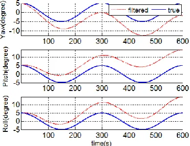
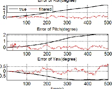
0.003 0.003 0.003 [image:6.595.210.401.256.404.2]The calculated attitude angle after complementary filtering is compared with the measured value from turntable platform. The results are shown in Fig. 5 and Fig. 6. The complementary filtering algorithm needs 277 time of scalar operation for each update at 10Hz sampling rate. The global variables take 72 bytes space while local variables take 260 bytes. Roll angle, pitch angle and yaw angle has the standard deviation of 0.31°,0.20° and 0.39°, respectively. As compared to the actual measurements from the turntable experiment, the error convergence after 100s.
Fig. 5: Error of attitude angle after filtering
Fig. 6: Error comparison of non-filtering and filtering
CONCLUSION
In the paper, we propose an error correction method using MARG sensor array. We compared the filtering performance with the traditional EKF algorithm. The experiment results indicate that both algorithms have similar filtering accuracy, but MARG algorithm can reduce the convergence time significantly. EKF is computational expensive with more than 7 times of scalar operations than our proposed MARG algorithm. Under low sampling rate (10Hz), the error calculated from our method is less than 0.5°.
Acknowledgment
[image:6.595.216.399.439.583.2]REFERENCES
[1]Du,H.Y., Hao, Y.L., and Zhao, Y.X., 2011. Systems Engineering and Electronics, 33(7): 1653-1657. [2]Gao, X.Z., Hou, Z.X., and Wang, B., et al., 2013. Control Theory & Applications, 30(2): 171-176.
[3]Guo, X.H., Yang, Z., and Chen, Z., et al., 2011. Transducer and Microsystem Technologies, 30(11): 149-152. [4]R. Mahony, T. Hamel, and J.M. Pimlin., 2008. IEEE Transactions, 53(5): 1203 -1218.
[5]Sabatini, A.M., 2006. IEEE Trans-actions on Biomedical Engineering, 53(7): 1346 – 1357. [6]Shi, Y., and Han, C.Z., 2011. Acta Automatica Sinica, 37(6): 755-759.
[7]Wang, K., Liu, L., and Du, X.J., et al., 2011. Journal of Astronautics, 32(4): 795-801. [8]Wang, Q.T., 2011. Journal of Convergence Information Technology, 6(6) : 202-211.