Wei Yu, Hongyan Li , Jiandong Li, Lin Jin, Kun Yuan
1
State Key Laboratory of Integrated Service Networks1,Xidian University, Xi’an, China 2
Department of Automation2, University of Science and Technology of China, Hefei, Anhui, China Email: [email protected]
Received June, 2013
ABSTRACT
Delay Tolerant Networks (DTNs) is a dynamic topology network, in which connection durations of each link are vari-able and paths between two nodes are intermittent. Most of protocols which are widely used in traditional wireless net-work are not suitable for DTNs. DTN adopts store-and-forward mechanism to cope with the problem of intermittent path. With limited storage of each node, it is a challenge for scheduling nodes’ transmission to avoid overflow of nodes’ buffers. In this paper we propose an optimal transmission scheduling algorithm for DTN with nodes’ buffer constraints. The object of the optimal algorithm is to get maximum throughput. We also present an algorithm for obtaining subop-timal transmission schedules. Our solution is certified through simulation, and it is observed that our solution can im-prove network performance in the aspects of avoiding overflow and increasing network throughput.
Keywords: DTN; Transmission Scheduling Algorithm; Throughput; Overflow
1. Introduction
Delay-Tolerant Networks (DTNs) [1] has characteristics of constrained storage, high delay and intermittent con-nections, which lead to no existence of end-to-end path between source and destination at most times. DTN ap-proaches this problem with store-and-forward mecha-nism. The nodes, existing in the system operating on aforementioned mechanism, firstly store messages re-ceived from the upstream ones, and then wait for connec-tion of outgoing links to send stored messages out. It's very challenging for relay nodes with limited storage. Once the amount of stored messages meets the upper bound of storage, overflow potentially happens in the relay nodes due to a period of outgoing link disconnec-tions. Since there is not enough storage space for new messages, relay nodes have to refuse new messages or discard old ones, causing energy waste and throughput decrease.
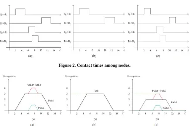
Although DTN networks are always mobile, in most cases, the node movements can be known in advance be-cause of their predictable trajectories. There have been a lot of DTN studies based on prediction [2-4]. Consider an example deterministic network of five nodes { ,1 2 1 2 as shown in Figure 1, in which contact times are known or can be explicitly predicted. Contact times among the five nodes are shown in Figure 2(a), in which 1 and are connected from to , and a link exists between R and D1 from to . Contact time between and is [6 , and the one between R
and D2 is [7,9].
, , , } S S R D D
S
R t2
10 t
,8]
5 t
t13 2
S R
Messages in 1 need to be transmitted to 1, but there isn't an end to end path between them. So the mes-sages should be firstly offloaded from 1 to R in their contact time [2,5] and then wait at R until
S D
10 S
t , when the connection between R and 1 begins. Similarly, 2 sends messages to R at
D S
6
t and R relays messages to 2 at
D t7. All the link rates are set to 1. Message forwarding sequences { ,1 1 and { 2, 2 are marked as path1 and path2 respectively. Contacts be-tween nodes on both paths are periodic and the least common multiple of their periods is 14. Their periodicity isn't shown in Figure 2 due to lack of space. The occupa-tion of messages on R 's storage space has been depicted in Figure 3(a) with the storage of R unlimited. If the upper storage bound of R is set to 3, R is full at
,D}
S R ,D
t } S R
5 and only until t10 able it is to free its storage as shown in Figure 3(b). So 2 cannot send messages to R since their contact time begins at and ends at t
S
6
t 8.
Under this situation, the contact times which can be util-ized are shown in Figure 2(b) and the theoretical average network throughput is 0.214, i.e. . But if the contact time between and R is replaced with
1 (5 2)\14 0 .214 1
S
Figure 2. Contact times among nodes.
Figure 3. Analytical results of occupations on storage space of relay node R. The black and blue lines represent the occupa-tion on R of path1 and path2 with time varying respectively. The peripheral red line is the superposioccupa-tion of black and blue lines, which has overlaps with the black line in some positions. The green line of dashes represents the upper bound of R's storage.
[2,4], shown in Figure 2(c), to restrict the message transmission on path1, there will be enough storage space in R for message transmission on path2 as shown in Fig-ure 3(c). After scheduling the contact times for transmis-sion, the theoretical average network throughput
in-creases to 0.286, i.e. ,
and no overflow happens.
[1 (4 2) 1 (8 6)] \14 0.286 [5,6] provide routing algorithm to realize optimal routing for pairs of nodes. But the transmission on one path may sacrifice throughput on other paths which share the same relay node with it since the relay's storage is limited, causing decrease of network throughput. The above-mentioned scenario includes more than one path. Such multi-flow problem has been studies well in con-nected works [7], but the algorithm is unsuitable in DTN due to its intermittent connection. [8-10] propose buffer management algorithm, which schedule message carding and forwarding in relay node. [8] chooses dis-carding old messages first to catch up with network up-date. But outgoing link which belongs to the path for new messages transmission probably begins late, so relay node still can't free its storage and such solution does no help in throughput increase. Although [9,10] adopt other drop mechanisms, they still cannot avoid the same prob-lem.
This paper proposed a transmission scheduling algo-rithm, which is based on the contact time features of links on different paths sharing the same relay node. This
algorithm deals with overflow by restricting transmission on some paths from their upstream nodes. We only de-scribe DTN networks of periodic pattern in order to get convenience when compare average throughput, but the transmission scheduling algorithm is also suitable for aperiodic pattern. Our solution not only optimizes the network throughput, but also cuts energy waste. It also can be used as a reference for routing algorithm.
The rest of the paper is organized as follows. We start with a model of network and transmission scheduling algorithms in Section II, and in Section III we analyze the model. Simulation results are presented in Section IV and followed by conclusion in Section V.
2. Model
In this section, we describe our model of network and how the network throughput is optimized through trans-mission scheduling algorithm.
2.1. Network Connectivity
Consider a network including n upstream nodes and n
downstream nodes represented by the sets
1 2 { , , , n}
S S S S and D{D D1, 2,,Dn} respectively. 's messages need to be transmitted to
, which is i's corresponding node in set D. Since i and i aren't connected directly, messages trans-mission between them must pass R, which is the only one
i S
S i
D
between R and i. Let denote the contact time between i and R in a period of T. i and R can communicate to each other since ingoing link exists dur-ing in s in e . Similarly, [ s,out e denotes the
contact time between R and . We can define and as:
0 [ s out s t t hers in t t others in ( ) i i in in i i out out v L v L
1 1},{S ,
i S R [ti ,ti
( )t
( ) ( ) L t L t ( ) in v t ( )t
i in {{ i i t t
[tin si ,tin ei
out i D 0, 0 [ i i in e i i out e t T t T ( ) i i t i t i
2 R D, }, { , ,S Ri
i i
t t
( ) i D ] 1 in ot
( )t
( )
( )
v t
, ,R D
] t ] S 1 out v in out v t S S ] , , , 2, , n n , n R Dn
1 p2,
/ i v ] i v i i
t t
] 0, i 1, 1, 2 D i RD t ( ) i in L t n S R S R } t i out L i in i out i i out v ) t i v i out v P 1, 2 1 ] i i RD 2, , 2,
{S ,
} i { , P p S R i in t v / i v , n (1)
Let denote rate function for ingoing link i , and is for outgoing link . Rate function
and are defined as: (
i in
v
where is the rate of connected ingoing link i , and is the rate of connected outgoing link i.
It is noted that there are n forwarding sequences, which can be represented by the set
RD
}}
in this network. Sequence is marked as path , so we can also present P as . i
p pn
2.2. Optimal Transmission Scheduling Algorithm
In this paper, our algorithm is able to avoid overflow in relay node and increase network throughput by altering lengths of contact times between nodes. We assume that all the messages received by R can be sent out in the pe-riod of T, i.e. each outgoing link can undertake transmis-sion task from its corresponding ingoing link. Let i denote the length of ingoing link i 's contact time is shortened by. Accordingly, the length of outgoing link
i's contact time is shortened by out to meet
the aforementioned assumption. Therefore the original contact times of links and in (1) are changed into [in s,in e i and [out s ,out e i in out respectively. The most important constraint here is that the sum of each path's occupation on R must be less than R's maxi-mal storage at any time. Let
RD i
f t denote i's occupa-tion funcoccupa-tion on R. Expression of
p ( ) i
f t is as follow:
0[ t
( ) in( ) ( )]
i i
out 0
i
f t
v t v t dt tTTherefore, the linear program computed the maximal
1 2 max 0 1 ( )] . . ( ) [ ( ) ( )] 0
in in e in s in in e in s n n n
in in e in s n n
T i i R
in out i
i i i in e in s
T
v t t t
s t f t v t v t dt C
t t t
(2)where f t( ) is a function representing the sum of all paths' occupation functions on R, and max
R
C is R's maximal storage.
It is important to note that this linear program is hard to solve due to its complex constraint, which must guar-antee no overflow at anytime. So we also propose a sim-plified algorithm called transmission scheduling algo-rithm (TSA).
2.3. Transmission Scheduling Algorithm
We simplify this problem by assuming that f t( ) only has one maximum beyond max
R
C during the period of T
under the assumption of unlimited storage of R, that is i for
t
1, 2, ,
i n
)
in (2). Let t denote the time when (
f t reaches its maximum, which is also the maximal value of f t( ). So t must satisfy the following inequality:
* *
( ) ( ) 0 , 0
f t f t t T t T
Therefore when the storage of R is set to max
R
C , the overflow Cover can be figured out as follow:
* max
( ) R
over
C f t C
We shorten the contact times to decrease the sum of message transmission of all ingoing links by . We certainly make sure the real-time value of
over
C
( )
f t is no more than max
R C
t
i in e
in this way. The shortening process is realized by wiping a part off each contact time in (1). The length of contact time shortened by is also repre-sented as i, which has the same meaning as in the linear program of (2). It is important to notice that the end time of the wiped part must be earlier than t, otherwise such shortening makes no contribution to overflow avoiding. Therefore the wiped part of ingoing link's contact time can be presented as in e i in . That
is if
* *
[min( ,t ti )t, min(t ,tie)] *
t t
in s
, change the contact time of link i in (1)
into i
S R
[ti ,tin ei t], otherwise change it into two parts,
*
[tini s,t ti] and . Accordingly, the contact time of outgoing link i in (1) is changed into
out s out e i in out . Therefore the linear program of
(2) can be simplified as follow: *
[ ,t tin ei ]
RD
*
*
0 1
1 1 1 2 2 2
1
min( , ) min( , ) 1
* 1
max ( )
1
= [ ( ) ( )
( )]
. . [ ( ) ( )]
0 min( , )
i in e
i i in e i
n T i in i
in in e in s in in e in s n n n
in in e in s n n
t t i i
in out over t t t t
i
i i
i in e in s
Th v t dt
T
v t t t v t t t
T
v t t t
s t v t v t dt C
t t t t
2 (3)
3. Model Analysis
In this section, we analyze the factor which can influence the performance of TSA.
To investigate what factor the increase of throughput is dependent on, we define following variables. Let Fi denote the total data flow of i in the period of T under the assumption of unlimited storage of R, i.e. without consideration of R's storage when computing i
p
F. So we use original L tiin( ) of (1) to calculate Fi. Expression of
i
F is as follow:
0 ( ) i i in
T
F
v t dtLet max denote maximal occupation of i on R's storage under the same assumption, which is represented as follow:
i
C p
max max ( ) 0
i
i
C f t tT
We define the ratio of data flow Fi to maximal oc-cupation max as
i
C i. A bigger i means attaining the same data flow of i at a lower cost of occupation on R, or gaining a better data flow at the same cost of occupa-tion. In the same period of T, better data flow means bet-ter throughput. i
p
can also show the relationship of contact times between an ingoing link and its correspond-ing outgocorrespond-ing link. A bigger i means longer overlap between their contact times along the time axis. It is im-portant to notice the minimal value of i is 1, which denotes no overlap between contact times.
Our solution in this paper is actually restricting trans-mission on the path with a smaller i to make room for the transmission on the path with a bigger i. In this way, the network can get a better data flow by utilizing the storage of relay node properly, avoiding some mes-sages staying in the relay node for a long while. If
1 i
for , our transmission scheduling algorithm will be useless since there is no possibility to increase throughput without overlaps.
1, 2,
i n
4. Simulation Results
We use MATLAB to do the simulation of a network with five nodes as the example shown in Section I, i.e. there are two paths in all. Contact times and link rates are
gen-erated randomly in our simulation, satisfying the follow-ing two conditions: i) guarantee at least one path's equals 1; ii) the outgoing link can undertake the trans-mission task of its corresponding ingoing link.
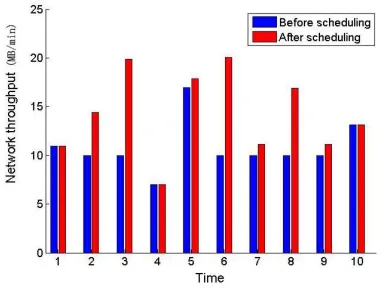
Contact times are generated a hundred times. For lack of space, we have chosen ten times of them to show their average throughput in Figure 4. We set relay node storage max
R
[image:4.595.62.289.86.206.2]C as 10. Except in the 1st, 4th and 10th times, throughput has been increased with the use of TSA. The same throughput in the 1st time is due to the fact that both 1 and 2 equal 1, and so is it in the 10th time. The reason for the same throughput in the 4th time is that there is no overflow before scheduling, i.e. the relay node storage is enough for the whole transmis-sion. In the 2nd, 3rd, 6th, 7th, 8th and 9th times, the throughput is 10 before scheduling, that is because there is only message transmission on the ingoing link which belong to a path with 1 before the storage is fully occupied.
Figure 5 illustrates how the average network through-put varies with 2, the ratio of data flow to occupation of path2. In this simulation, 1 is kept as 1. It is ob-served from Figure 5 that the network throughput in-creases with 2 after scheduling. A bigger 2 means longer overlap between contact times, but the potential of overlap can not be exploited without transmission sched-uling algorithm. That's why the network throughput is constant before scheduling.
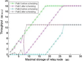
Figure 6 illustrates how the average throughput on each path varies with max
R
C , the maximal storage of relay node. Before scheduling, the throughput of path1 gets to its maximum first while the throughput maximum of path2 comes earlier after scheduling. Before scheduling, the throughput of path2 has been restricted to 0 when
max
R
C is relatively small, while the throughput of path1 increases with max
R
C until path1 completes its whole transmission. The reason is that the start of 2 's con-tact time is relatively late, leading to the storage of R
fully occupied by transmission on path1. When max
S R
R
[image:4.595.328.518.577.721.2]C is big enough to undertake the transmission on all the paths,
narios.
6. Acknowledgements
[image:5.595.89.258.86.213.2]This work is supported by the National Science Founda-tion (60972047, 61231008), NaFounda-tional S\&T Major Pro-ject (2011ZX03005-004, 2011ZX03004-003, 2011ZX- 03005-003-03, 2013ZX03004007-003), Shaanxi 13115 Project(2010ZDKG-26), National Basic Research Pro-gram of China (2009CB320404), ProPro-gram for Changji-ang Scholars and Innovative Research Team in Univer-sity(IRT0852), the 111 Project (B08038) and State Key Laboratory Foundation (ISN1002005, ISN090305). Figure 5. Simulation results of network throughput with
1
fixed to 1 and 2 varying.
REFERENCES
[1] K. Fall, “A Delay Tolerant Network Architecture for Challenged Internets,” in Proceedings of ACM SIGCOM pp. 27-24, 2003.
[2] S. Merugu, M. Ammar and E. Zegura, “Routing in Space and Time in Networks with Predictable Mobility,” Geor-gia Institute of Technology, Tech. Rep., 2004.
Figure 6. Simulation results of each path's throughput with varying.
R
Cmax [3] J. Francois and G. Leduc, “Routing Based on Delivery Distributions in Predictable Disruption Tolerant Net-works,” Ad-Hoc Networks, Vol. 7, No. 1, 2009, pp. 219-229.doi:10.1016/j.adhoc.2008.02.006
the throughput of path2 will increases with max
R
C until
the maximal value it can reach. [4] M. Huang, S. Chen, Y. Zhu, et al., “Topology Control for Time-evolving and Predictable Delay-tolerant Networks,” in IEEE MASS, 2011.
After scheduling, transmission on either paths may be restricted when max
R
C is relatively small. The reason is that max
R
C is too small to undertake the transmission during the contact time before overlap advents, so wiping contact time from either path will lead to the same net-work throughput. With the increase of max
R
C , transmis-sion scheduling algorithm will choose to leave storage to path2 first by restricting transmission on path1 since 2 is bigger than 1, and the throughput of path2 increases with max
R
C until path2 completes its whole transmission. When max
R C
max
is big enough to undertake the transmission on all the paths, the throughput of path1 will increases with CR until the maximal value it can reach.
[5] S. Jain, K. R. Fall and R. K. Patra, “Routing in a Delay Tolerant Network,” in ACM SIGCOMM, 2004, pp. 145-158.
[6] D. Hay and P. Giaccone, “Optimal Routing and Schedul-ing for Deterministic Delay Tolerant Networks[C]” Wire-less On- Demand Network Systems and Services, 2009. WONS 2009. Sixth International Conference on. IEEE, 2009, pp. 27-34.
[7] I. Chlamtac, A. Farag’o, H. Zhang and A. Fumagalli, “A Deterministic Approach to the end-to-end Analysis of Packet Flows in Connection Oriented Networks,” IEEE/ ACM Transactions on Networking, Vol. 6, 1998, pp. 4422-4431.
[8] V. N. G. J. Soares, J. J. P. C. Rodrigues, P. S. Ferreira and A. M. D. Nogueira, “Improvement of Messages Delivery time on Vehicular Delay-tolerant Networks,” in Interna-tional Conference on Parallel Processing Workshops (pp. 344-349). IEEE. 2009.
5. Conclusions
In this paper, we propose a transmission scheduling algo-rithm by simplifying optimal algoalgo-rithm in DTN, which is able to avoid overflow, increase network throughput and save node energy. Our algorithm is validated by com-puter simulation. It is observed that this algorithm assur-edly increases network performance since it can take good advantage of constrained storage of relay node by
roperly assigning it to different paths.
[9] S. Rashid, Q. Ayub, “Effective Buffer Management Pol-icy DLA for DTN Routing Protocals under Congestion,”
International Journal of Computer and Network Security, Vol. 2, No. 9, 2010. pp. 118-121.
[image:5.595.89.259.261.384.2]