© 2018, IRJET | Impact Factor value: 6.171 | ISO 9001:2008 Certified Journal | Page 1164
POWER QUALITY IMPROVEMENT IN SOLAR BY USING FUZZY LOGIC
CONTROLLER
S. Sakthitharani
1, R. Sangeetha
2, S. Subha
3, G. Deivamani
4.1,2,3
Dept of Electrical and Electronics Engineering, Tamilnadu,India
4Assitant professor, Dept of Electrical and Electronics Engineering, Tamilnadu,India---***---Abstract -
Photovoltaic (PV) systems are grid-connected via
an interfacing converter which operates with Maximum Power Point Tracking (MPPT) controller in order to feed the grid by the maximum allowable solar power. Nonlinear loads affect the system power quality. Conventionally single-phase shunt active power filter (APF) can be used to improve the power quality in terms of current harmonics mitigation and reactive power compensation. In this paper, the PV interfacing inverter is controlled using a predictive control technique to perform both functions of power quality improvement in addition to transferring the PV maximum power to the grid. A Fuzzy logic control algorithm is applied for MPPT. The proposed technique does not require an accurate system model and can easily handle system nonlinearity. The system performance is investigated using a MATLAB simulation model.
Index Terms—power quality, shunt APF, predictive control, grid-connected PV systems, MPPT, Fuzzy logic control.
1.INTRODUCTION
Harmonics is one of the power quality issues that influence to a great extent transformer overheating, rotary machine vibration, voltage quality degradation, destruction of electric power components, and malfunctioning of medical facilities [1]. Power quality improvement has been given considerable attention due to the intensive use of nonlinear loads and the limitations required by international standards such as IEEE519-1992[2].Those limitations were set to limit the disturbances and avoid major problems in power system. Since linear and/or non-linear single-phase loads are rapidly increasing, zero sequence component and current harmonics are generated. This causes overheating of the associate distribution transformers that may lead to a system failure, especially in weak networks [3]-[5]. Photovoltaic (PV) power supplied to the utility grid is gaining more and more visibility, while the world’s power demand is increasing. Global demand of electrical energy is growing by high rate due to the requirement of modern civilization. Recently, energy generated from clean, efficient and environmentally friendly sources has become one of the major challenges for engineers and scientists. Among them, PV application has received a great attention in research because it appears to be one of the most efficient and effective solutions to this environmental problem [6]. There are two topologies used to connect the PV with the grid; two stages and single stage PV system. A two stage is the traditional type and consists of a CUK DC/DC converter direct coupled with PV array and a
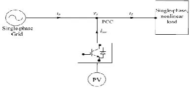
[image:1.595.335.529.598.688.2]grid connected universal bridge inverter. In single stage PV system, the DC/AC inverter has more complex control goals; Maximum Power Point Tracking (MPPT) and output current control. Regardless its control complicity, single stage PV system is more efficient and cheaper than two stages system. For connecting the PV system to the grid, there are three widely used grid interactive PV systems; the centralized inverter system, the string inverter system and the AC modulator the Module Integrated Converter (MIC) system. Among these, the MIC system offers “plug and play” concept and greatly optimizes the energy yield [7].With these advantages, the MIC concept has become the trend for the future PV system development but challenges remain in terms of cost, reliability and stability for the grid connection [8].Conventionally single phase shunt active power filter(APF) uses an inverter for harmonics elimination and reactive power compensation [9]-[10].A grid connected PV system with active power filtering feature has been presented in [11][13].However, measuring the load current is mandatory. In this paper, an inverter is used as a single-phase shunt active power in addition to interfacing a power of a photovoltaic (PV) as shown in Fig.1. Fuzzy Logic Control (FLC) is used as a robust controller for MPPT; this control technique can handle the model uncertainties in addition to easily handle the nonlinearity. The single-phase shunt active power filter (APF) uses a predictive control technique to mitigate of the grid current harmonics and improve the power factor. The proposed control strategy provides a multifunction with a simple controller incorporating Phase Locked Loop (PLL) independency, less sensors, ease of practical implementation, and reduced system size and cost. The proposed system performance is investigated for most of the conditions using a MATLAB simulation model.
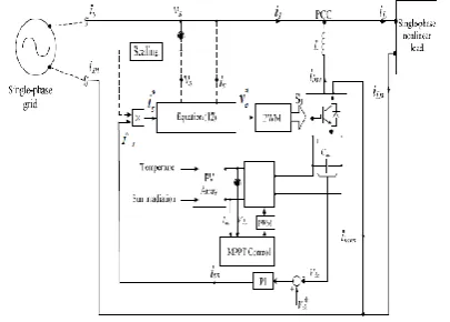
© 2018, IRJET | Impact Factor value: 6.171 | ISO 9001:2008 Certified Journal | Page 1165 Fig.2. The overall system modelling including control
signal
II. PV SYSTEM MODELLING
The single-phase multi stage grid connected system is shown in Fig. 2. It consists of a PV array followed by step up stage, which feeds a predictive current controlled voltage source inverter acts as an APF that feed s current into the single phase grid and linear/non-linear single phase loads.
A. Photovoltaic Cell equivalent circuit
The traditional equivalent circuit of a solar cell is represented by a current source in parallel with one or two diodes. A single-diode PV cell model for m is illustrated in Fig. 3, including four components: a photo current source, Iph, a diode parallel to the source, a series resistor, Rs, a shunt resistor, Rsh. The DC current generated, Ip h, when the cell is exposed to light varies linearly with solar irradiance [14]. The shunt resistance RSh is inversely related with shunt leakage current to the ground. In general, the PV efficiency is insensitive to variation in RSh and the shunt-leakage resistance can be assumed to approach infinity without leakage current to ground. The net cell current of the cell is the difference of the light-generated current, Iph, and the d iode current, Id, as shown in Fig. 4. Equation (1) describes th e I-V characteristic of the ideal photovoltaic cell.
[image:2.595.62.237.653.724.2]where Ipv,cell is the current generated by the incident light (it is directly proportional to the sun irradiation), I0,cell is the leakage current, q is the Boltzmann constant [1.60217646× K is the Boltzmann constant [1.3806503× J/K],T is the temperature of the p-n junction, and a is the diode identity constant
Fig: 3 Single-diode model of theoretical PV cell [5]
Practical arrays are composed of several connected photovoltaic cells and the observation of the characteristics at the terminals of the photovoltaic array requires the inclusion of additional parameters to the basic equation (2):
where Ipv and I 0 are the photovoltaic and saturation currents of the array and Vt = (NskT)/q is the thermal voltage of the array with Ns cells connected in series.
The light generated current of the photovoltaic cell depends linearly on the solar irradiation and is also influenced by the temperature according to (3) [15]:
+
where Ipv,n is the light-gene rated current at the nominal condition (usually 25◦C and 10 00W/m2),∆T = T – T
n (being Tand Tn the actual and nominal temperatures ), G [W/m2] is the irradiation on the device surface, and Gn is the nominal irradiation. The diode saturatio n current I0 and its dependence on the temperature may be expressed by equation (4) [16]:
where Egis the band gap energy of the semiconductor (Eg ≈1.12 eV for the polycrystalline Si at 25◦C [17]), andI
0,nis the nominal saturation current.
III.MODEL OF CUK CONVERTER
© 2018, IRJET | Impact Factor value: 6.171 | ISO 9001:2008 Certified Journal | Page 1166 turns ratio the leakage inductance and loses fly back
transformer are neglected here. But the leakage inductance affect the switch and diode transitions .
The magnitude of Lm decides the boundary between continuous and discontinuous current modes (CCM)and (DCM).The series connection of switch with DC generator result in pulsating input current[18].
IV.PROPOSED MPPT USING FUZZY LOGIC CONTROL
In order to track the time varying maximum power point of the solar array depending on its operating conditions of insulations and temperature, the MPPT control technique place an important role in the practical PV system. A variety of MPPT schemes and several sensor-less approaches have been proposed in the literatures [20].
This paper proposes MPPT control technique with FLC.thg output power of PV arrays varies with weather conditions ;solar irradiation and atmospheric temperature. Therefore ,real time MPPT control for extracting maximum power from The PV panel becomes indispensable in PV generating system[21]-[22].
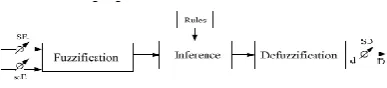
MPPT using FLC gains several advantage of better performance, robust and simple design. In addition, this technique does not require the knowledge of the exact model of the system and it can handle the nonlinearity . The main parts of FLC; fuzzification ,rule-base , inference and defuzzification ,are shown in fig,6.
MPPT using FLC provides bet performance robust and simple design. The proposed FL-MPPT control shown in fig7.it has two input and one output .the two FLC variables are the error and change for error CE at sampled times j defined by
(9) (10) (11)
Fig.4 Gird connected PV system with cuk converter
v
Where:
Efficiency of the cuk converter D: DC-DC converter duty cycle PV array output current PV array output voltage DC bus current (inverter side) DC bus voltage (inverter side)
[image:3.595.341.535.370.414.2]The fly back transformer provides isolation and also the voltage ratios are multiplied by turns ratio. Where are the PV power ,current and voltage respectively at instant j .E(j) shows the if the load operating point at the instant j is located on the left or on the maximum power point on the p-v characteristic where it is equal to zero at MPP. While the change of error CE(j) expresses the moving direction of the point where the control action duty cycle D used for the tracking of the MPP by comparing with the saw tooth waveform to generate a PWM signal for the fly-back boost
Fig.5 Fuzzy Controller Diagram
For example, if the operating point is far to the left of the MPP, that is E is PB, and CE is ZE, then it is required to largely increase the duty ratio i.e., D should be PB to reach the MPP. In the defuzzification stage, the fuzzy logic controller output is converted from a linguistic variable to a numerical variable still using a membership function. This provides an analog signal that will control the power converter to the MPP [24].
© 2018, IRJET | Impact Factor value: 6.171 | ISO 9001:2008 Certified Journal | Page 1167 Fig 6,membership function of (a) error E-(b)change of
error CE-(c) duty ratio D
V PROPOSED INVERTER CONTROL TECHNIQUES
The proposed system show in fig.8 consist of PV array, cuk converter DC link capacitor ,and a universal bridge connected at the PCC to a three phase grid through in interface inductance . the compensator reference current is calculated from the sensed grid current drawn by the nonlinear and three phase loads connected to the grid. the reference current is computed by using capacitor voltage control[25].the compensation objectives is to compensate for load current harmonics, reactive power compensation and to regulate the DC bus doing bidirectional active power exchange between the Dc side load/source and the power system grid .
The compensation functions are executed simultaneously where a three phase nonlinear load are fed from both the grid pv system. the performance is tested from the following cases:
Case 1: at normal conditions Case 2: the load increases
Case 3: the solar irradiation decreases
Case 4: the atmospheric temperature increases.
[image:4.595.80.247.78.214.2]The proposed control system block diagram is shown in
Fig. 7. Block diagram of the proposed control of inverter
Symb
ol Values
Rated power 199 W Rated voltage 26.3V Rated current 7.6A Open circuit voltage 32.9V short circuit current 8.21A Number of series cell 54 Number of parallel cell 1
Number of series module 1 Number of parallel
module 1
C PV module capacitor 4700µF Tc Atmospheric temperature Gn Solar irradiation 1000
W/ Vs Grid voltage in RMS 220V
DC references voltage 420 V DC bus capacitor 3.0mF Sampling frequency 3.2mH Switching frequency 5µF F Line frequency 50KHz
Table 3:Fly-back transformer parameters
Fig.8. the universal bridge is controlled with a predictive control strategy.it requires the measurement of the grid voltage and current at PCC and the inverter DC link voltage. The measurement of the load current and the injected inverter current are not required. The inverter references current is extracted using DC-link capacitor voltage control method. The DC-link voltage, , are subtracted from the reference voltage, . A PI controller acts on the resultant error the DC –link voltage is maintained constant and the power balance between the grid, inverter ,and the load is achieved as the capacitor compensate instantaneously the difference between the grid and the load power[26]-[29]. Multiplication of the PI controller output with PCC per unit voltage forms the grid current reference. Ideal voltage is assumed. The reference and measured grid current and the PCC voltage are used to predict the inverter reference voltage required to force the actual current to track its reference. The predictive current controller presented in [27] is used to control the interfacing.
Power converter of the DG unit. The predicted converter output voltage is expressed in terms of the reference and actual grid current by
[image:4.595.58.261.582.727.2]© 2018, IRJET | Impact Factor value: 6.171 | ISO 9001:2008 Certified Journal | Page 1168 The grid reference current (k) in (13) represents three
phase sinusoidal grid current. The introduced sampling time delay is less significant sampling frequency is high (28). T
herefore, the predictive control method proposed for the multifunctional inverter can compensate both of the grid current harmonics and reactive power required also transfers the PV power, thus grid current become sinusoidal and the DC bus are regulator during bidirectional active power exchange between the DC side load source and the grid. This method provides simple control algorithm without a PLL, minimizes the number of sensor as the load and inverter current are not measure, and provides ease of piratical implementation.
VI PERFORMANCE INVESTIGATION OF THE
PROPOSED SYSTEM
The proposed system shown in Fig.2 is simulated using a MATLAB/simulink model to investigate is performances. The system parameter are listed in table to and the high frequency transformer parameter of the fly-back DC-DC converter shown in Fig.5, are listed in table 3. The PCC voltage is 220 v .The nonlinear load is represented by a three phase diode rectifier feeding an inductive load representing a harmonic current producing a source. The resistance and the inductions of the inverter coupling inductor, are
and respectively. DC link capacitor of 3.0 mF is used. The reference voltage for this loop is sat at 420 v and the inverter switching frequency f is 5 KHz.
Quantity Symbol Values
Inductance 28µH DC resistance DCR primary 0.008 Ohms DC
inductance DCR Secondary 0.472 Ohms Self-Resonant
Frequency SRF 360KHz Saturation
current 10.5 A Turns ratio Pri:Sec 1:12
The system performance is investigated for the following cases:
Case 1: from 0.2 to 0.4 s; a single-phase nonlinear load of 250 W is fed from both the gird and the PV unit at solar irradiation of 1000 W/m2 and an atmospheric temperature of 25oC.
Case 2: at 0.4 s, the load increases to 400 W.
Case 3: at 0.6 s, the solar irradiation decreases to 900 W/m2. Case 4: at 0.8 sec, the temperature increases to 35oC.
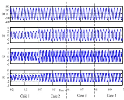
The simulation results are shown in Fig. 9. The grid voltage waveforms at the PCC, vs, are shown in Fig. 9(a). Typical
[image:5.595.333.534.292.453.2]non-linear load current, iL, is shown in Fig. 9(b). Its total harmonic distortion (THD) is 31 %. The inverter current, iinv, injected at the PCC is shown in Fig. 9(c). As a result, sinusoidal grid current, is, with near unity power factor is achieved as shown in Fig. 9(d). The grid current THD is compared before and after compensation. The APF improves the THD from 31% to 3.2% which comply with the IEEE Std. 519-1992. An almost steady DC-link voltage, Vdc, is shown in Fig. 10. The load active and reactive powers PL, QL are increased from 250 W to 400 W and from 50 VAR to 80 VAR as shown Fig. 11(a). The active and reactive powers of the grid are shown in Fig. (b), the grid active power, Ps are increased from 130 W to 250 W while the grid reactive power Qs maintained near zero. Fig.11(c) presents the power supplied by the PV unit which is almost maintained at 140 W with small variations duo to the change of solar irradiation and atmospheric temperature
Fig.8.Simulation result: (a) grid voltage, v,(b) load current, ,A(c) inverter current, , (A),and (d)grid
[image:5.595.54.254.451.607.2]current, .
© 2018, IRJET | Impact Factor value: 6.171 | ISO 9001:2008 Certified Journal | Page 1169
In this paper, a PV system is interfaced to the grid via a multifunctional interfacing inverter. A MPPT fuzzy logic controller is employed to feed the grid by the maximum allowable PV power. A simple predictive current control algorithm is used. The system performance is investigated using a MATLAB/ Simulink model at different cases of load variation, atmospheric temperature variation and solar irradiation variation. The inverter achieves functions of supplying the available power from the PV unit into the loads in addition to improving the power quality in terms of grid current THD and power factor. The results comply with the limits of the IEEE Std. 519-1992.
REFERENCES
[1] R.D. Henderson, and P. J. Rose, ‘‘Harmonics: The effects on power quality and transformers,’’ IEEE Transaction on Industrial Applications, Vol.30, No.3, May/Jun 1994, pp.528-532.
[2]IEEE Std. 519-1992, Recommended Practices and Requirements for Harmonic Control in Electric Power Systems, 1992.
[3]T.M. Gruzs, "A survey of neutral currents in three-phase computerpower systems, Industry Applications, ," IEEE Transaction on Industrial Electronics, Vol.26, No.4, Jul/Aug 1990, pp.719-725.
[4]F. Liu, X. Zhang, Z. Xie, P. Xu, and L. Chang, "Shunt active power filter for harmonic and reactive current compensation in wind conversion systems," IEEE Power Electronics Specialists Conference, PESC, 2008, pp.2329-2332.
[5]B. Singh, and S. Sharma, "SRF theory for voltage and frequency control of IAG based wind power generation," IEEE International Conference on Power Systems, ICPS 2009, pp.1-6
[6] T. Shimizu, O. Hashimoto, and G. Kimura, “A novel high performance utility-interactive photovoltaic inverter system.” IEEE Transaction on Power Electronics, Vol. 18, No. 2, Feb. 2003, pp. 704–711.
[7] S. B. Kjær, J. K. Pedersen, and F. Blaabjerg, “A review of single-phase grid-connected inverters for photovoltaic modules,” IEEE Transaction on Industrial Applications, Vol. 41, No. 5, Sep./Oct. 2005, pp. 1292–1306.
[8] J. M. Carrasco, et.al., “power-electronic systems for the grid integration of renewable energy sources: A survey,” IEEE Transaction on Industrial Electronics, Vol. 53, No. 4, Aug. 2006, pp. 1002–1016.
“Stud S.SAKTHITHARNI,
Dept of Electrical & Electronics Engineering, Paavai Engineering College, Namakkal, Tamilnadu”
“Stud S.SUBHA,
Dept of Electrical & Electronics Engineering, Paavai Engineering College, Namakkal, Tamilnadu”
“Stud R.SANGEETHA,
Dept of Electrical & Electronics Engineering, Paavai Engineering College, Namakkal, Tamilnadu”
G.DEIVAMANI.,M.E, Assistant professor,
Dept of Electrical & Electronics Engineering, Paavai Engineering College, Namakkal, Tamilnadu”
![Fig: 3 Single-diode model of theoretical PV cell [5]](https://thumb-us.123doks.com/thumbv2/123dok_us/8133561.797583/2.595.62.237.653.724/fig-single-diode-model-of-theoretical-pv-cell.webp)