© 2018, IRJET | Impact Factor value: 6.171 | ISO 9001:2008 Certified Journal | Page 194
Speed Variation Using Cone Ring Traction Drive
Dhiraj Gunjal
1, Rohan Khaire
2, Kiran Deore
3, Nilesh Gund
4, B.S.Dange
51,2,3,4 BE student Mechanical, SND COE & RC, YEOLA, Maharashtra, India 5 Asst. Prof. Mechanical, SND COE & RC, YEOLA, Maharashtra, India
---***---Abstract –A transmission which can change through an
infinite number of gear ratios between maximum value and minimum value by a continuously variable transmissions (cvt). This is different than other mechanical transmissions that have selected discrete gear ratios. The constant angular velocity is maintained by flexibility of cvt, which is beneficial for fuel economy. Small vehicles can maintain balance between fuel efficiency and cost of manufacturing. Motor scooters and snowmobiles use CVTs. Motor scooter and Snowmobile CVTs are rubber belt pulley CVTs.
Key words:. CVT, mechanical transmissions, revolutions per
minute.
1.1INTRODUCTION
The beginning of the latest transmission concept such like six speed stepped automatic, manual and dual clutch transmissions places latest challenges for a state-of-the-art CVT transmission concept.
1.1.1 DESCRIPTION OF KRG:
In comparison with other continuously variable transmissions (CVTs) this causes significant advantages in terms of manufacturing costs and efficiency. Basic Characteristics of the KRG Concept In order to achieve good vehicle driving dynamics, any kind of automatic transmission must have the capability to translate the driver’s gas pedal input for a dynamic acceleration into a quick change of transmission gear ratio, but at the same time smooth torque transition. For the KRG concept, quick ratio changes require a high torque capability of the friction contact and the shortest possible delay of the involved dynamic systems. Any control function needed beyond the basic mechanical ratio change system, such as the hydraulic pressure control and very high power requirements for the gear change actuator of conventional CVTs, necessarily leads to unwanted delays in the shifting process. Thus, avoiding a hydraulic system and using an actuator system with low “shifting” forces were decided very early during the KRG concept development as the basic means to achieve a sporty performance feeling. Today’s modern engine fuel island maps are getting “flatter”, which means that CVT transmissions can only take benefit of their larger ratio range, if the associated improvement in the engine operating point is not compensated by a low transmission efficiency, particularly at light loads. The demand for applying clamping forces to the power transmission elements has a decisive influence here, because these force levels in friction-wheel
transmissions are quite high and must also be applied constantly. As an ideal solution combined torque sensor and actuator was designed for the KRG, as described below. For automotive mass production, robust design and low manufacturing costs are imperative requirements.
1.1.2 THE KRG DESIGN:
The basic components of the KRG variator, such as rollers, clamping and adjustment unit are all purely mechanical, as described in more detail below.
Variator
The variator is consist of an input cone , an output cone and a transfer ring which can be located around the input and output cone. when changing diameter and angle of the cones, start-up and overdrive ratio is change. As well as the ratio spread can easily be adapted to vehicle requirements and installation space.
Clamping Unit
The required clamping force is obtain throughout the axial displacement of the output cone. A mechanical torque sensor base on the ball and ramp system, transforms the output torque into an axial pressure force with very high efficiency. By locating this mechanism in the path from the output shaft, all load changes such like road induce torque peaks are automatically detect and changed corresponding axial force. The sensor and actuator in a simple mechanical system avoids the need of costly sensor technology and electronic / hydraulic control systems commonly originate in conventional CVTs.
Adjustment Unit
© 2018, IRJET | Impact Factor value: 6.171 | ISO 9001:2008 Certified Journal | Page 195 is provided by the cone rotation. at some stage in constant
ratio driving, the control frame is kept at its neutral position.
Contact Point and Traction Fluid
All CVT-concepts based on the friction system use one or more points for the power transferring. The power capacity of the friction system is determined by the normal load in the contact point and the friction (traction) coefficient of the tribological system. While the maximum normal load is limited by the permissible bearing loads and maximum allowable contact stress, extensive research work has shown great improvement potential, if the function of the variator fluid can be reduced to torque transfer via shear forces in the oil. Whilst the bearings are provided with a commercial lubricant , a specially developed traction fluid is used for power transmission in the variator. The traction oil is abounding to the friction contact by splashing from the output cone dipping into the fluid level. As a result, the friction fluid needs no pumpability at low temperatures. The optimization of this oil can be focused on price, traction coefficient and temperature stability. Compared with conventional CVT fluids, an increase in friction value of more than 50% has been achieved during development and appears to have not yet reached the limits of feasibility. This friction value increase translates directly into a significant improvement of the power density and package of the transmission.
Vehicle Installation
The cone-ring concept has been developed for both front (FWD) and rear wheel drive (RWD) applications. Whereas RWD installations have been investigated in various studies, the present emphasis in development is on the FWD derivatives because of their higher potential market volume. Due to the opposite location of the large cone diameters, the KRG has a small distance between variator input and output shaft and as a result a small centre distance between transmission input and output shaft. For an engine torque up to 180 Nm, axle distances around 160 mm are possible with a start-up ratio greater than 16, which covers the majority of current FWD installations.
Starting Device
In principle, the KRG can be driven with a converter, wet clutch or dry clutch. While an automatic dry clutch makes sense for small vehicle applications due to cost pressures and lower comfort demands, comfort-oriented vehicles tend to be equipped with a converter.
Control System
The control strategy is divided into the different hierarchies of low level internal transmission control and high level drive train control strategy. While the high level logic selects the appropriate transmission ratio set point in line with performance and fuel economy requirements for the particular driving condition, the low level control applies
this ratio in a closed loop control for the electromechanical actuation system. The shorter the time delay is to respond to step changes in transmission ratio set point, the more freedom is available for the “right” driving strategy. This strategy is highly dependent on regional customer preferences as well as the OEM’s “brand identity”. The current KRG vehicle demonstrator with a 85 kW gasoline engine offers three driving modes, an economy CVT-mode with emphasis on vehicle fuel consumption, a sporty CVT-mode with high acceleration performance, and a manual 6-speed tip-mode operated by the driver. The KRG control system is design and the initiate clutch have been designed by using MATLAB SIMULINK and dSPACE, Together with the models for the vehicle and the power train, this approach enables a complete CAE based dynamic system simulation and optimization before the first hardware tests.
1.2 LITERATURE REVIEW
The literature review of the cone ring traction drive which is used in various application such as power utility industrial application and many more
1. Ivanov R Konstantin assumed that Necessity of the controlled coordination of forces on different wheels takes place. In earlier the Recently continuously variable transmission (CVT) in the form of gear differential with mobile closed contour has been developed. The patents on the simplest adaptive transmission were created. The work is dedicated to working out of self-adjusting motor-wheel on the basis of theory of mechanisms and machines.
DESIGN OF A SELF-ADJUSTING MOTOR-WHEEL
The main parts of motor-wheel with the adaptive mechanical redactor are: 1. Frame. 2. Hub.
2. Wisam M. Abu-jadayil tell that friction drive is speed reducer proposed by Flugrad and qamhiyah in 2005 was mainly investigated in this paper. Those rollers fail by fatigue. So , this research built a numerical simulation model to find the optimum size of those rollers which gives the least contact stresses and so the longest fatigue life.Then those rollers were replaced by hollow ones.
Traction Drive Selection
The output speed different than the input speed produced by speed reducer. other types of speed reducers in use, including traction drive speed reducer.
Problem Statement and Solution Technique
© 2018, IRJET | Impact Factor value: 6.171 | ISO 9001:2008 Certified Journal | Page 196 the main disadvantages of friction drive systems compared
to gear drive systems is the size required. The size of a friction drive system must be larger to account for the stress induced due to the normal force required to prevent slip.
3. Dalling Ryan addresses A Positive Engagement, Continuously Variable Transmission (PECVT) using a positively busy member accept for a continuously variable transmission ratio over a specified range such like gear teeth, to spread torque. This research is on investigation of PECVTs to establish a classification system and governing principles.
4. Kevin R. Lang addresses the U.S. government enacts new regulations for automotive fuel economy and emissions.
5. Todd J. Furlong Judy M. Vance, Pierre M. Larochelle Erdman and Sandor (1991) defines a mechanism as “a mechanical device that has the purpose of transferring motion. Mechanical engineers are often required to design mechanisms to perform tasks separately or as part of a larger machine.
6. H. Komatsubara, T. Yamazaki, have given traction drive CVT have low noise and a low vibration.
7. Neil Sclater, Nicholas P. Chironis addresses input and output functions always rotate in the same direction, irrespective of the number of bearings, and different results can be achieved by slight alterations in bearing characteristics. All these factors lead to specific advantages:
• Space saving: The outside diameter, bore, and width of the bearings set the envelope dimensions of the unit.
The housing needs by only large enough to hold the bearings. In most cases the speed-reducer bearings can be builds into the total system, conserving more space.
• Quiet operation. The traction drive is between nearly perfect concentric circles with component roundness and concentricity, controlled to precise tolerances of 0.00005 in. or better. Moreover, operation is not independent in any way on conventional gear teeth. Thus quiet operation is inherent.
• High speed ratios. As a result of design ingenuity and use of special bearing races, virtually any speed reducing or speed-increasing ratio can be achieved. MPB studies showed that speed ratios of 100,000- to-1 are theoretically possible with only two bearings installed.
• Low backlash: Backlash is restricted mainly to the clearance between backs and ball retainer. Because the balls are preloaded, backlash is almost completely eliminated. The three MPB units variety of designs possible:
• Torque increaser: This simple torque increaser boosts the output torque in an air-driven dental hand pieces, provide a
2 1⁄2-to-1 speed reduction. The speed reduces as the bearing’s outer ring is kept from rotating while the inner ring is driven; the output is taken from a coupling that is integral with the ball retainer. The exact speed ratio depends on the bearing’s pitch diameter, ball diameter, or contact angle. By stiffening the spring, the amount of torque transmitted increases, thereby increasing the force across the ball’s normal line of contact.
• Differential drive: This experimental reduction drive uses the inner rings of a preloaded pair of bearings as the driving element. The ball retainer of one bearing is the stationary element, and the opposing ball retainer is the driven element. The common outer ring is free to rotate. Keeping the differences between the two bearings small permits extremely high speed reductions. A typical test model has a speed reduction ratio of 200-to-1 and transmits 1 in.-oz of torque.
• Multi-bearing reducer: This stack of four precision bearings achieves a 26-to-1 speed reduction to drive the recording tape of a dictating machine. Both the drive motor and reduction unit are housed completely within the drive capstan. The balls are preloaded by assembling each bearing with a controlled interference or negative radial play.
8. Wisam M. Abu-Jadayil, Mousa S. Mohsen had used the friction drive speed reducer proposed by Flugrad and Qamhiyah in 2005 was mainly investigated in this paper. In Six intermediate cylindrical rollers to transmit motion by using self actuating traction drive. Those rollers fail by fatigue. So, this research built a numerical simulation model to find the optimum size of those rollers which give the least contact stresses and so the longest fatigue life. Then those rollers were replaced by hollow ones. The numerical simulation give results in case of having the rollers hollow, contact stresses values decreased which means longer fatigue lives of those rollers. The hollow rollers were found to live more than 30 times the solid ones under same loading conditions.
1.3 METHODOLOGY
1.3.1 Types of CVT
The types of CVT are as given below:
Variable-diameter pulley:
In this system it consist of two V-belt pulleys split perpendicular to their axes of rotation.
Toroidal CVT :
© 2018, IRJET | Impact Factor value: 6.171 | ISO 9001:2008 Certified Journal | Page 197 Cone Ring Transmission KRG
The KRG GIF has a shows potential transmission under the development that offers the driver a multifunctional power train with various driving programmes.
Continuously variable ratio change (CVT-Mode) 6- or 7-Gear Automatic
Simulated manual shifting service (Step-Mode).
Benchmark investigations regarding manufacturing costs show clear advantages for the KRG since basic functions are realized by simple mechanical solutions. Low tolerance requirements on transfer parts generate even more advantages for the system and price comparison.
1.3.2 DESCRIPTION:
The ratio changed by two cones and one ring continuously These transfer parts are separated via an oil film from each other. Therefore the traction characteristic of this oil has a great importance. To improve the oil optimally with regard to power transfer, the oil storages for the bearings and the continuously variable friction power transfer are separated from each other. As a start element all common systems in the automotive industry are possible in principle. As the KRG needs no hydraulic-oil pump due to its mechanical pressure unit an automated dry clutch with its high efficiency is best qualified. The quick ratio change to the required ratio position is effected via little steering motions on the transfer ring by the adjusting unit. This basic principle allows to the related to the steering motion of a bike high dynamics adjustment with low adjustment power.
1.4 CONE RING TRACTION DRIVE
This is used in this project. With the Cone Ring traction Drive has a promising transmission under development that offers the driver a multifunctional power train with various driving programmed.
Continuously variable ratio change (CVT-Mode) 60 Gear Automatic/manual Shifting
The principle of cone ring traction drive is not only single to front wheel drive configurations, but also offers capable options for rear wheel drive arrangements and for high torques.
1.4.1 PRINCIPLE OF OPERATION
The continuously ratio changed is performed by two cones and one ring. These transfer parts are in constant contact with each other. Consequently the traction features of this drive having a huge importance. To improve the torque characteristics with regarding to power transfer, the output cone can be displaced axially.
1. Motor (1 phase Ac motor, 50 watt, 230 Volt, 0-6000 rpm(variable):
Motor is a Single phase AC motor, Power 50 watt, Speed is continuously variable from 0 to 6000 rpm. The motor speed is change due to electronic speed variator. Motor is a commutator motor i.e., the current to motor is supplied to motor by means of carbon brushes. By changing the current supply to these brushes the power input to motor is changed by the electronic speed variator, thereby the speed is also is changes. Motor is foot mounted and is bolted to the motor base plate welded to the base frame of drive.
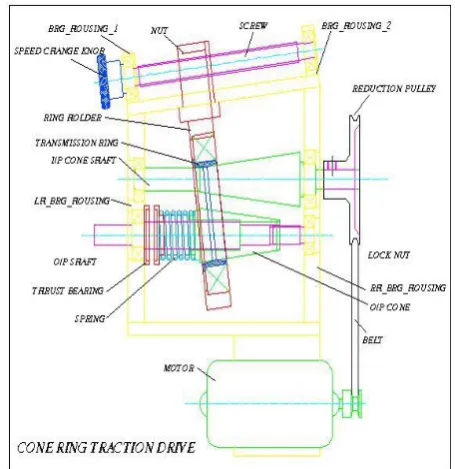
[image:4.595.318.546.268.503.2]Setup: Construction of cone ring traction drive is as given below:
Fig. Cone Ring Traction Drive
The Cone ring traction drive consists of the following parts:
2. Belt Drive
The power from the motor is supplied to the input shaft of the mechanism by means of an open belt drive. The drive comprises of the motor pulley mounted on the motor shaft, the belt FZ 6x 500, and reduction pulley mounted on the input shaft.
3 . L H Bearing Housing
The L H Bearing housing is a structural steel member (EN9), that supports bearings 6003 zz and 6004 zz. The upper end of the baign housing is milled at angle of 70, to receive the slide arrangement, where as the bottom end receives the casing support plates.
© 2018, IRJET | Impact Factor value: 6.171 | ISO 9001:2008 Certified Journal | Page 198
4. R H Bearing Housing
The R H Bearing housing is an structural steel member (EN9), that supports bearings 6005 zz and 6201 zz . The upper end of the bearing housing is milled at angle of 70, to receive the slide arrangement, where as the bottom end receives the casing support plates.
5. Input cone shaft
The material of input cone shaft is an high grade steel (EN24) member which is held in ball bearings 6003zz and 6005 zz , in the L H & R H bearing housings respectively. The input cone shaft carries the reduction pulley at one end.
6. Output shaft
The material of output shaft is an high grade steel (EN24) member which is held in ball bearings 6004zz and 6201 zz , in the L H & R H bearing housings respectively. The output shaft carries the output cone at the center which is keyed to it, where as the output shaft is provided external threading M15x1.5 pitch which receives KM-2 locknut for torque adjustment.
7. Output cone
The output cone is a high grade steel (EN24) member keyed to the output shaft. Provision is made to slide the output cone axially to adjust the torque.
8. Helical Compression spring
The helical compression spring is held at one end of the output cone while its other end is supported on the thrust bearing holder. The helical compression spring provides with the axial fore required for the appropriate torque.
9. Thrust bearing
Thrust bearing is held between the helical compression spring and the LH bearing housing. It is held in the thrust bearing holders supported on the output shaft.
10. Variator Cone Ring
The variator cone ring is a high grade steel (EN24) member held in ball bearings 6017 zz in the ring holder. It overlaps the input and output cone. It is translated along the slant edges of these cones to achieve the changes in speed, by changing the effective radii in contact.
11. Ring Holder
Ring holder is an structural steel member (EN9), that holds the variator cone ring in ball bearing 6017zz, whereas carries the speed adjustment nut at its top end.
12. Speed Adjustment screw
The speed adjustment screw is a high grade steel member (EN24), which is held in ball bearing supported in the LH and RH screw bearing housings which are welded to the slide
arrangement on the LH and RH bearing housings as mentioned above.
13.Speed Adjuster nut
The adjuster nut is held on the ring holder and screw, the rotation of the screw effects the translation of the nut thereby changing the contact radii between the input and output cones, and thus the speed changes.
14. Speed Adjuster knob
The speed adjuster knob is mounted on the screw, rotation of this knob effects the speed changes.
1.4.2 WORKING OF CONE RING TRACTION DRIVE
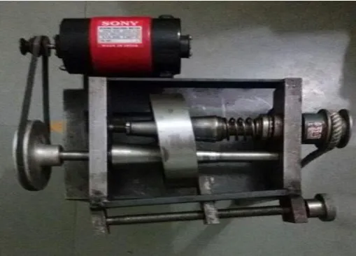
[image:5.595.310.565.502.685.2]Motor is which is connected to the Input Cone Shaft via Reduction Pulley and Belt arrangement. The input cone shaft which is integral and is mounted in ball bearings in the LH & RH bearing housing respectively. The output cone shaft is mounted in ball bearings in the LH & RH bearing housing respectively and output cone is keyed to it. The output cone can slide axially and the displacement is governed by KM3 locknut. The preload in the system is maintained by the helical compression spring and the thrust bearing arrangement. The speed changing arrangement comprises of the speed adjuster nut mounted on the speed adjuster screw held in ball bearings in the bearing housings 1&2 respectively.
© 2018, IRJET | Impact Factor value: 6.171 | ISO 9001:2008 Certified Journal | Page 199 Fig. Side view of designed model
A) General: Input cone shaft is drive by the motor via open belt drive. The input cone transmits this motion to the variator cone ring which in turn drives output cone and thereby the output shaft.
B) Speed changing: The speed changing knob when turned rotates the speed changing screw thereby effecting the translation of the nut and thereby that of the ring holder and the variator cone ring. This translation changes the contact ratio between the two cones thereby effecting speed change. Minimum 60 different speed changes are possible considering the effective slant edge length on either cone. The speed changes are continuous and can be made without stopping or disconnecting the drive.
C) Torque adjustment: The output cone moves axially in direction by KM3 locknut which is governed the displacement. The preload in the system is maintained by the helical compression spring and the thrust bearing arrangement. When the output cone is axially displaced it changes the radial load and thereby the torque transmitted because of the the variator cone ring connects.
1.5 OBSERVATION TABLE
The observations during experimentation are as follows:
Table: Observation Table
LOADING UNLODING
MEAN SPEED WEIGHT
(gm) SPEED rpm WEIGHT (gm) SPEED rpm
200 1190 200 1180 1185
400 1175 400 1165 1170
600 1160 600 1150 1155
800 1155 800 1145 1150
1000 1145 1000 1140 1142.5
1200 1136 1200 1134 1135
1400 1116 1400 1114 1115
1600 910 1600 920 915
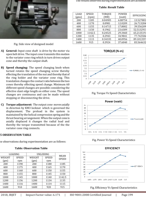
1.6 RESULT ANALYSIS
[image:6.595.42.282.76.245.2]The results observed during experimentation are as follows:
Table: Result Table
LOAD
(gms) SPEED (rpm) TORQUE (NM) POWER (watt) EFFICICENCY
200 1185 0.04905 6.08754 13.527881
400 1170 0.0981 12.0209 26.713284
600 1155 0.14715 17.8002 39.556209
800 1150 0.1962 23.6309 52.5132933
1000 1142.5 0.24525 29.3460 65.2135192
1200 1135 0.2943 34.9841 77.742506
1400 1115 0.34335 40.0956 89.1013597
1600 915 0.3924 37.6040 83.564632
[image:6.595.44.554.109.799.2]
Fig. Torque Vs Speed Characteristics
[image:6.595.282.565.149.678.2]Fig. Power Vs Speed Characteristics
[image:6.595.301.570.156.438.2]© 2018, IRJET | Impact Factor value: 6.171 | ISO 9001:2008 Certified Journal | Page 200
CONCLUSION
Continuously variable transmission system can be used for changing the speed and allows engine to remain at its highest efficiency. Fuel economy is improved by this system. CVTs operate smoothly so there are no gear changes which cause sudden jerks. Small tractors uses simple hydrostatic or rubber belt CVTs. A lot of power 10-15 MPH can be delivered by them without need of clutch. Motor scooter and snowmobile CVTs is rubber belt or variable pulley CVTs.
Acknowledgment
We feel great pleasure to present the Project entitled “SPEED VARIATION USING CONE RING TRACTION DRIVE”. But it would be unfair on our part if we do not acknowledge efforts of some of the people without the support of whom, this seminar would not have been a success. First and for most we are very much thankful to my respected HOD Prof. Bhamare V.G. For his leading guidance in this project topic. Also he has been persistent source of inspiration to us. We would like to express our sincere thanks and appreciation to Principal Dr. Kudal H.N. for his valuable support. Most importantly we would like to express our sincere gratitude towards our Friends & Family for always being there when we needed them most. We work on this project by the support of our college and Prof. Bharat Dange, who guided us at any difficulties come across
REFERENCES
1) Konstantin Ivanov , “Self-Adjusting Motor-Wheel with CVT”, International Journal of Engineering and Innovative Technology (IJEIT) Volume 2, Issue 5, November 2012, ISSN: 2277-3754 ISO 9001:2008 Certified.
2) Wisam M. Abu-Jadayil a,*, Mousa S., “ Design and Manufacturng of Self Actuating Traction Drives with Solid and Hollow Rollers”, Jordan Journal of Mechanical and Industrial Engineering, Volume 4, Number 4, September 2010 ISSN 1995-6665 Pages 467 – 476
3) Ryan R. Dalling, “An Investigation of Positive Engagement, Continuously Variable Transmissions”, 2008
4) Kevin R. Lang, “Continuously Variable Transmissions”, May 3, 2000
5) Todd J. Furlong Judy M. Vance, Pierre M. Larochelle, “SPHERICAL MECHANISM SYNTHESIS IN VIRTUAL REALITY”, Proceedings of DETC98: Design Automation Conference September 13-16, 1998, Atlanta, Georgia.
6) H. Komatsubara, T. Yamazaki, “Research and Development of Cone to Cone Type CVT”, 12th IFToMM World Congress, Besançon (France), June18-21, 2007
7) Neil Sclapter, Nicolas P. Chronis, “Mechanisms and Mechanical Devices Sourcebook”, Third Edition.
8) I. A. Chironis, “Mechanisms and Mechanical Linkages.”
9) Erdman and Sandor, “Engineering Mechanism”.
10) V. B. Bhandari, “Design of Machine Elements”.
BIOGRAPHIES:
Dhiraj B. Gunjal, SND COE Yeola, Pune University, Department of Mechanical Engineering.
Rohan B. Khaire, SND COE Yeola, Pune University, Department of Mechanical Engineering.
Kiran R. Deore, SND COE Yeola, Pune University, Department of Mechanical Engineering.
Nilesh G. Gund, SND COE Yeola, Pune University, Department of Mechanical Engineering.