© 2017, IRJET | Impact Factor value: 5.181 | ISO 9001:2008 Certified Journal |
Page 668
Continuity in the development of seamless mobility:
An approach for a system-of-systems environment
Albert Albers
1, Ralf Reussner
2, Armin Kurrle
1, Erik Burger
2,
Georg Moeser
1, Nikola Bursac
1, Simon Klingler
1, Matthias Behrendt
1 1Institute of Product Engineering (IPEK), Karlsruhe Institute of Technology, Germany
2
Institute for Program Structures and Data Organization (IPD), Karlsruhe Institute of Technology, Germany
---***---Abstract
–
Today’s product innovations increasingly consist of tightly coupled heterogeneous smart systems. This trend can also be observed in the automotive domain. In future seamless mobility, the car will be one part of a com-plex system-of-systems where many partly independent working teams from different disciplines and companies with high interrelations are involved in development of the mobility system. In practice, many different methods, pro-cesses and tools are used in product development, which leads to the challenge of obtaining consistency and continui-ty over multiple development generations and product gen-erations, level of detail, and different projects. As changes to the product models can have a wide impact, management of change plays an important role. This research article pre-sents two integrated approaches to enable multi-level traceability in interdisciplinary product development. The presented approaches use semantic technologies for hetero-geneous development artefacts and model-based techniques to build consistent product models for cyber-physical sys-tems and syssys-tems-of-syssys-tems. Finally, a methodology to support management of change in distributed product de-velopment based on the SPALTEN problem-solving process is presented. The integration of these three approaches with the change management methodology supports distributed development of seamless mobility systems with high con-sistency and traceability.Key Words: Seamless Mobility, Traceability, Systems-of-Systems, Smart Mobility, Connected Car, Model-based Systems Engineering, RDF, Change Management, PGE - Product Generation Engineering
1.
INTRODUCTION AND MOTIVATION
Today’s innovations in product development are increas-ingly based on a close interaction between mechanics, electronics and software engineering. Information and communication technology open up further possibilities. Future products are becoming increasingly interdiscipli-nary, complex, autonomous, connected and with embed-ded intelligence (1).
This trend can also be observed in the automotive and transportation industry in terms of increasing digitaliza-tion. The car of the future will be connected with other “smart products” (e.g., smart buildings, smart grids, smart
factories, smart logistic) (2) enabling a seamless mobility. “Seamless” is understood as accessible, intermodal, con-nected, safe, secure, effective, and efficient in order to be affordable, value creating, environmentally friendly, resili-ent and acceptable. Such a seamless mobility enables new business models for IT, retail market, insurance and oth-ers. The car itself is part of a complex, interconnected sys-tem-of-systems (SoS), where many people from different disciplines are involved in development.
Because of the highly interrelated product models in the distributed and partly independent development teams, changes to requirements or goals can have a wide impact. Inconsistency can lead to serious problems in product development process. In particular, it shifts projects risks to later phases of development with often severe financial impacts.
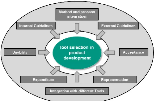
During a research cooperation between the connected car department of a German car manufacturer and the IPEK – Institute of product engineering of Karlsruhe Institute of Technology in the period of 2013 – 2016, the following observations of development project were made: In prac-tice, a variety of heterogeneous tools and representation forms are used in product development to explain product models. They support collaboration in product develop-ment. It is however hardly possible to unify these meth-ods, processes and tools, especially in a systems-of-systems environment. This is traced back to a variety of boundary conditions on selection of methods and tools (see Figure 1).
For example, the form of representation can vary between different development phases. In early phase of product development, sketches or posters and mockups are gladly used to describe product models. Tools like Microsoft Power Point can be used to do that. In later development phases, requirements and specifications have to be de-scribed in detail. Tools like IBM Rational Doors or model-based techniques with direct link to implementation or shape are chosen.
© 2017, IRJET | Impact Factor value: 5.181 | ISO 9001:2008 Certified Journal |
Page 669
Internal guidelines have to be addressed or existing con-tracts or licences have to be considered because of eco-nomic or legal reasons.
External guidelines, e.g. a supplier requests a certain re-quirements documentation format like can lead to some tool selection as well in product development projects. Usability and expenditure is important, especially if a product model has to be shared among a large group of stakeholders. Microsoft Office and natural language or sketches are chosen very frequently in this case. Model-based techniques can be used to transform a specification directly into software which can facilitate development. The general acceptance of tools by the individual users is very important when making a tool selection. It is based on individual preferences of developers which exist either because of rational or emotional reasons.
For this paper, we have identified the following research questions:
1. How can continuity be addressed in product
devel-opment of systems-of-systems?
2. How can explicit relations between heterogeneous
development artifacts be modeled in a distributed SoS environment to achieve consistency?
3. How can the management of changes be supported in
a distributed product development environment to ensure continuity?
4. How can the developed approach be applied to
achieve seamless mobility?
This paper is structured as follows: In section 2, we will give an overview of the state of the art. In section 3, we will address research question 1 by presenting a classifica-tion of continuity dimensions in product engineering. In
section 4, we will describe how the KaRDF and Vitruvius
methods can be used for consistent modelling, answering research question 2. In section 5, we will present a meth-od for the management of changes, answering research question 3. Finally, section 6 gives a conclusion as well as
an outlook on future work and answers research question 4.
2.
STATE OF THE ART
2.1
Systems Engineering
Systems Engineering (3) is an interdisciplinary approach and is intended to enable the development of systems methodically. SE focuses on a holistic and collaborative understanding of stakeholder requirements, the discovery of solutions and the documentation of requirements, as well as the synthesis, verification, validation and develop-ment of solutions. The entire problem is considered from concept development to system development. System engineering provides suitable methods, processes and
best practices for this purpose. A system in the context of
this work is a model of a entirety, which (4):
has relations between attributes (inputs, outputs,
states)
is an assemblage of connected parts or subsystems
is differentiated by its environment or supersystems
(through a system boundary).
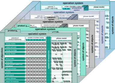
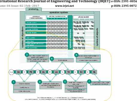
Using systems theory the product development can be described with the research concept of the PGE – Product Generation Engineering (5). PGE describes that the most products are developed in generations (6). Based on an existing product – the reference product – like a former product generation or a competitor’s product, a new de-velopment is started. The new product generation consists of subsystems that are varied in order to be carried over and of newly developed subsystems (7). In the context of seamless mobility as a SoS, the PGE-approach can be fur-ther developed to SGE - Systems Generation Engineering. Systems Engineering is furthermore used to describe product engineering processes. The product development process is understood as the transformation of objectives into objects by performing certain activities by an opera-tion system (8). A model that can describe development processes including the system of objectives, the operation system with activities of product engineering and activi-ties of problem solving and the project’s system of objects as well as the interaction between different product gen-erations is the iPeM – integrated Product engineering Model (see Figure 2) (9). It consists of different layers:
product Gn, product Gn+1, validation system, production
system and strategy. Furthermore, it consists of different activities, which are described with the SPALTEN problem solving methodology (10). This way, different methods can be added to the activities and support product developers in the product development process (11).
2.2
Cyber-physical
Systems
and
Systems-of-Systems
[image:2.595.36.289.97.260.2]© 2017, IRJET | Impact Factor value: 5.181 | ISO 9001:2008 Certified Journal |
Page 670
A cyber-physical system (CPS) is a combination of physical and computational components, which are connected by a network at multiple and extreme scales. It may re-organize and re-configure itself dynamically and is usually
created with a high degree of automation, so that the phys-ical processes can be monitored and controlled in real-time. The computational components affect the physical components as well as vice versa. (12)
According to MAIER (13), a system-of-systems (SoS) is an
assemblage of systems, where each system can be seen itself as a system but with some special characteristics:
Each is capable of independent action and fulfills a
purpose of its own.
The individual systems of the set are managed
inde-pendently—to fulfill their stated purposes.
Cyber‐physical systems-of-systems are CPS which exhibit the features of systems-of-systems.
Based on existing research, ALBERS ET AL. (14) summarize
the following challenges in development of SoS:
SoS are an assemblage of constituent systems where
the constituent systems are able to handily operate in an independent manner (e.g. a car, smartphone). They are separately acquired and integrated, and maintain a continuous operational existence independent of the system-of-systems.
The Constituent systems of the SoS might fulfill
objec-tives independent of the system-of-systems and the
system owner may have little interest in fulfilling the SoS objectives. SoS objectives can conflict with objec-tives of the constituent systems.
Independent organizations can be involved in
devel-opment of constituent systems. A comprehensive, co-ordinating SoS organization is not necessarily present. Many Stakeholders are involved.
Constituent systems might be in different phases of
their product life cycles. The development is not neces-sarily synchronized or centrally managed.
Development of the SoS is never completed. Changes to
the constituent systems or adding and removing new systems may appear frequently. Because of high inter-relations this can affect other constituent systems.
SoS are complex. Nobody has a full overview on
every-thing. Constituent systems are to a high degree hetero-geneous and are a “Black Box” for other organizational units.
2.3
Semantic Technologies and Metadata
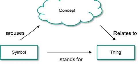
Semantics is generally defined as a subdivision of linguis-tics, which deals with the meaning of language or (linguis-tic) signs (15). In computer science, semantics are often used with the goal of supporting knowledge management. Semantic models are intended to support communication among people, machines and human-machine interaction. The resulting challenges are illustrated in the semiotic
triangle (see Figure3) (16).
operation system
operation system
operation system
operation system
manage knowledge manage changes
activities of product engineering
activities of problem solving
S P A L T E N
manage projects
detect profiles
model principle solution and embodiment built up prototype detect ideas
sys
tem
o
f
reso
u
rces
validate and verify
heute
phase model
s
y
s
te
m
o
f
o
b
je
c
ts
s
y
s
te
m
o
f
o
b
je
c
ti
v
e
s
produce market launch analyse utilization analyse decommission
Handlungssystem product gn
[image:3.595.111.494.165.439.2]operation system
© 2017, IRJET | Impact Factor value: 5.181 | ISO 9001:2008 Certified Journal |
Page 671
Knowledge is formalized based on the projection of a reali-ty section into a corresponding semantic representation on a computer. Metadata is understood to mean hierarchi-cally ordered as well as structured data about data. In general, metadata is used to make statements about a
particular record. Prominent example is the so-called Re-source Description Framework (RDF). Metadata can be interpreted by machines to derive new (semantic) metadata (inference) based on rules. Furthermore, they enable a context-specific search and thus more efficient access to explicitly existing knowledge. Thus, semantic metadata also allows conclusion of new information out of existing data (17). An example of an RDF graph can be seen in Figure 4.
2.4
Model-driven Development
Model-Driven engineering is a development paradigm that puts domain specific models and their utilization with analysis and generation tools in the center of the devel-opment process. It always makes use of the following con-cepts (18): First, domain- specific languages (DSL) express domain concepts. Thus, they reduce the complexity in the modelling of systems. DLSs are defined using metamodels, which themselves are defined using a standardized, fixed meta-metamodel. Second, transformations engines are used to transform these models into instances of other domain-specific languages or into textual representations of other formalisms, such as programming languages or textual data formats.
The Systems Modeling Language (SysML) (19) is a deriva-tive of the UML2 standard for systems engineering. SysML features a set of nine diagram types, which cover require-ments, structural, and behavioural view points, which can be used for the modelling of hardware, software, and pro-cesses.
Prior research on adapting model-based
systems engineering (MBSE) concepts with SysML to the domain of mechanical engineering in order to increase continuity has been done the authors (20).
The Eclipse Modeling Framework (EMF)1 is a development
framework for model-driven development that is imple-mented using the Java-based Eclipse platform. The EMF
project encompasses several sub-projects for managing, querying and transforming model-based data.
3.
DIMENSIONS OF CONTINUITY IN PRODUCT
EN-GINEERING
EDWARDS AND HOWELL (21) demand for traceability model-ing a relationship between the requirements, the design, and the final implementation of the system in product
development. ALBERS ET AL. have identified three
dimen-sions of a continuous flow of knowledge (22). We have extended these dimensions by a fourth dimension to con-tinuously describe product models in product engineering.
1. Level of detail
2. Temporal consistency
3. Consistency between projects
4. Consistency between partial models
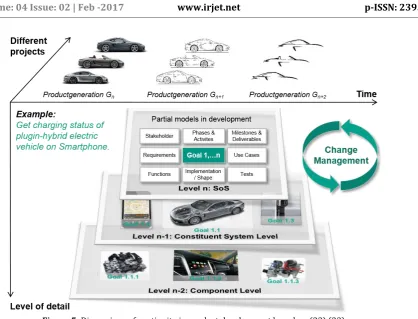
This is reflected in the context of systems-of-systems in the following. We will use the example of a SoS develop-ment goal to explain the dimensions of continuity (see Figure 5).
Level of detail: In development of complex systems and systems-of-systems, the development is subdivided into different organizational units on multiple levels. In earlier phases of product development, a description of the prod-uct is possible only on the top level, e.g. “As a user, I want to receive the charge status of my electric vehicle on my smartphone.” In later phases, the goal defined on SoS-Level has to be decomposed into goals for the correspond-ing constituent systems or components. As changes can occur on all levels of detail in product engineering, conti-nuity between different levels has to be guaranteed.
Temporal consistency: Product models change over
time.The operation system in product development (e.g.
developers, tools used for describing product models) can
1 http://www.eclipse.org/modeling/emf/, retrieved
2016-12-13
[image:4.595.44.286.166.278.2]Figure 3: The semiotic triangle (16)
© 2017, IRJET | Impact Factor value: 5.181 | ISO 9001:2008 Certified Journal |
Page 672
also change. Temporal consistency describes the use of the same product model over several development and product generations, so information of the transfered parts can be connected consistently even if the operation system changes. Especially in SoS context, product devel-opment life cycles can be different which leads to further challenges.
Consistency between projects: The third dimension represents the need for continuity throughout different product development projects. Consistency across differ-ent projects is necessary in order to be able to implemdiffer-ent a uniform or modular approach, using common parts in different products (e.g. same Online Connectivity Unit enabling similar SoS services in different car models). This makes it possible to make the information transparent when changing a component in a product, identifying the affected products from different projects.
Consistency between partial models: Products can be
described by nine partial models (23).The following
par-tial models coverall three systems of product engineering:
Requirements
Goals
Use cases
Functions
Stakeholder
Implementation / Structure
Tests
Milestones & deliverables
Phases & activies
According to EILETZ (24), continuity between all these
partial models is required in order to enable traceability, e.g. between requirements, design and implementation. Changes to an element of a product model can occur very frequently in product development. This can have implica-tions to other related elements in all identified dimen-sions. In practice, because of the heterogeneity of product
models, an integrated Change Management approach is
necessary to obtain consistency in the described dimen-sions.
4.
CONTINUOUS AND CONSISTENT
DOCUMENTA-TION OF PRODUCT MODELS
In this section, we present two integrated approaches, which enable traceability and which improve consistency in a distributed, interdisciplinary, and partly independent working product development environment. The first
approach KaRDF enables traceability through linking
het-erogeneous development artifacts of systems-of-systems, independent from their representation. The second
ap-proach Vitruvius is a model-based framework for the
syn-chronization of software engineering models on different levels of abstraction, which is applied in a cyber-physical environment. Furthermore, a similar, prototypical ap-proach for the synchronization of 3D CAD data with SysML system models in mechanical engineering is referenced. It
shows an option to extend the Vitruvius approach for
[image:5.595.103.522.64.383.2]in-terdisciplinary models.
© 2017, IRJET | Impact Factor value: 5.181 | ISO 9001:2008 Certified Journal |
Page 673
4.1
Traceability between heterogenous artefacts
– the
KaRDF
approach
The Karlsruhe RDF approach for product development -
KaRDF allows the continuous documentation of product models by providing a metadata scheme and an inference model for heterogeneous development artefacts consider-ing the four dimensions of continuity presented in chapter 3.
The requirements and objectives for the approach were derived from two descriptive studies in the context of real Connected Car development projects in order to align the approach to the actual needs of developers in practice. The empirical study shows that developers use artefacts to share their knowledge. Depending on product develop-ment phase, level of detail, project or docudevelop-mented partial model, methods and tools vary, even if there are high de-pendencies. This is caused by changing boundary
condi-tions (see also chapter 1). Figure6 shows an example from
[image:6.595.139.485.102.289.2]the Connected Car domain, how artefacts are used for development of system of objectives in different phases and in different development projects. On SoS-Level, a portfolio list is used to describe connected car services for different cars. These services are further described in a functional description in early stage on SoS-Level. In later phases, a concept description is created and a specification or a system model. In the investigated case study, Mi-crosoft Excel is used for defining the portfolio, a functional description with sketches is created in Microsoft Power Point and a detailed specification is created with IBM Ra-tional Doors, Microsoft Word or in a Web-based Wiki in-cluding model-based approaches (e.g. SysML). Many refer-ence products are used in order to describe the connected car services (e.g. a specification from a weather provider). Besides the listed documents, many relations to further development artefacts where identified (e.g. a project schedule, test cases, system documentation).
Figure 6: Using semantic Metadata to link heterogeneous development artefacts
[image:6.595.306.559.334.746.2]© 2017, IRJET | Impact Factor value: 5.181 | ISO 9001:2008 Certified Journal |
Page 674
In order to improve continuity and traceability between these kinds of development artefacts, a metadata scheme was developed based on the semantic technology RDF. The RDF scheme includes attributes that allow description of development artefacts as well as references to a functional or system structure, stakeholders, development phases, product generations or other development artefacts.
The RDF schema from KaRDF (in the following referenced
with prefix “KaRDF”) contains 9 metadata types and 32 predicates, which can be used to define RDF statements (see Table 1).
In an independent working and distributed SoS environ-ment, it cannot be guaranteed that all developers
contrib-ute to the metadata database. Therefore, KaRDF provides
an inference engine which allows generating further knowledge out of existing product development metadata. Rules have been defined which allow derivations from the function or building structure of systems, stakeholder relations, relations between development artefacts or from reference products of other product generations. Figure 7 shows an example how the inference engine works. If metadata exists, which gives information about content of a specification - e.g. a specification “describes” content of a specific car - and relevant stakeholders of the specific car are known (e.g. a Stakeholder is “responsible” for development of the specific car), than it can be derived that the Stakeholder has an interest in the specification (e.g. he wants to get “informed” when changes to the specification occur).
Figure 7: Example of deriving implicit relations from existing
metadata knowledge in KaRDF
The approach is implemented with the Apache Jena Framework in a web-based prototype which was used during an empirical study in five Connected Car develop-ment projects. The participant’s defined metadata for de-velopment artefacts created in the dede-velopment projects. Finally, the participants have been interviewed in order to evaluate the approach. All participants on the one hand agree, that the approach can be integrated well in an SoS environment where distributed, interdisciplinary and partly independent working development teams have to collaborate. The participants also agree, that continuity is
improved when using KaRDF in the four dimensions
pre-viously introduced. On the other hand, the participants claim a high effort in creating and maintaining the
metada-ta. Nevertheless, 4 out of 5 participants say that the benefit
of using KaRDF to improve continuity in product
devel-opment is higher than the effort to create and maintain the metadata.
4.2
Traceablity on model level
During the development and implementation of systems, developers create heterogeneous artefacts on different levels of abstraction. For example, the architecture of a system can be specified using the SysML standard, while the concrete implementation of software and hardware components is then realized with general-purpose pro-gramming languages, such as C or Java, and CAD tools for the mechanical design of system components. SysML al-ready defines a concrete form of representation. Further-more, it does not support all kinds partial models, but offers means to create links between the partial models that it supports.
Since these artefacts describe the same system on differ-ent levels of abstraction, they have to conform to each other to give a consistent description of the system. For example, the software implementation of a system must adhere to the interface definitions that are specified in a SysML system model. This is already important if the de-velopment process follows a strict refinement from ab-stract models to more concrete models and program code, and is aggravated further when e.g. architecture-relevant changes to the code must be propagated back to the sys-tem models. In current development processes, this con-sistency is often only checked manually; this is, however, a tedious and error-prone activity for developers. Model-based approaches offer the opportunity to define con-sistency relations across models of different abstraction levels, if all models are defined within the same technical space, for example the Eclipse Modeling Framework. Con-straint languages such as OCL and transformation engines such as QVT or ATL can be used to detect inter-model inconsistencies , and to re-establish consistency. This is especially interesting when model transformation are already used for generative techniques, i.e. that parts of the software are generated automatically from model-based descriptions.
[image:7.595.40.283.461.567.2]Within mechanical engineering disciplines, different types of descriptions of systems have to be considered as well. Often functional, logical and physical representations are differentiated. Especially traces between different repre
[image:7.595.315.553.661.747.2]© 2017, IRJET | Impact Factor value: 5.181 | ISO 9001:2008 Certified Journal |
Page 675
sentations are important within models to check impacts of changes and to re-establish consistency (25). E.g. a tex-tual description of functionality has to be checked after changes on the geometry in a CAD model have been ap-plied.
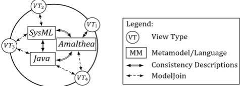
VITRUVIUS (26), (27) is a view-based, model-driven frame-work for the management of consistency between hetero-geneous models, i.e., models that are instances of different metamodels. Information is contained in a single underly-ing model (SUM), which represents all the information that is available about the system under development. The SUM conforms to a customized metamodel that is specific to the domain in which the Vitruvius approach is used; for example, in the automotive domain, the it may contain the metamodels of SysML, AMALTHEA and other standards, which are combined to form a modular SUM metamodel (see Figure 8). The metamodels are included non-intrusively and do not have to be adapted to work with the VITRUVIUS approach.
To express the traces between the elements of the
meta-models, VITRUVIUS defines a language framework for
con-sistency description and restoration that consists of three languages for reactions, mappings and invariants. Since VITRUVIUS is a view-based approach. All information in the SUM can only be retrieved or manipulated via specialized
views. For the definition of view types and views, V
ITRUVI-US uses the ModelJoin language (28). The consistency
preservation mechanism is triggered by changes to one or
several views. The preservation mechanism of VITRUVIUS
then reacts on a list of changes to propagate them to the SUM.
VITRUVIUS has been implemented as a prototype in the Eclipse Modeling Framework and can thus be used with any Ecore-conforming metamodel. So far, it has been ap-plied to software architecture models (29) and model-based representations of programming languages (30).
Outside of pure software engineering, it has been applied in the systems modeling of energy networks (31).
Implementation of traces from SysML models to 3D prod-uct data in CAD has been established within a research project (32). In this case it was shown without a SUM since CAD objects has been duplicated to SysML objects, which were used to trace to the physical parts. The basic
applica-bility was shown. An adaption to the VITRUVIUS framework
would make the traces more versatile.
5.
MANAGEMENT OF CHANGE IN DISTRIBUTED
AND INDEPENDENT DEVELOPMENT TEAMS
Main reasons for a loss of consistency and continuity are changes which can occur on different levels in product development. The implementation of a change can also be seen as a problem whereas the management of changes in a distributed environment has fractal character. This means that the same process must be processed at differ-ent levels and in differdiffer-ent phases by differdiffer-ent problem solving teams. For this reason, a process model has been developed for the management of changes, which is based on the problem-solving methodology SPALTEN (10). The methodology is intended as a support for the management of changes in product development in distributed and partly independent working environments providing de-velopers an instruction to handle changes when using
KaRDF and Vitruvius in orderto maintain consistency and continuity in product development. The process model consists of seven steps and 13 activities of management of change (see Figure 10). In addition to the above-mentioned activities, it must be examined in each step whether the problem-solving team responsible for as-sessment, decision and implementation of the change is adequately staffed and that all parties concerned are in-volved.
Situation Analysis (SA): The situation analysis is the first step of management of changes and forms the basis for the further processing. Changes can occur due to both internal and external factors. In the case of independent and dis-tributed SoS development teams, changes to constituent systems are possible without communication to all rele-vant stakeholders. Therefore, three activites are necessary in situation analysis: Observe changes, identify change and collect information. The knowledge which is present in
KaRDF metadata and derived implicit relations allows identification of relevant product development artefact
supporting situation analysis. KaRDF is used for getting
artefacts of systems or functions which change.
Problem selection (PE): In problem selection, the infor-mation available is delimited to the change-relevant data. The cause and effect is determined by the change. Two activities are required: detect affected partial models,
define change. KaRDF gives input for the definition of the
[image:8.595.36.290.346.505.2]change, e.g. which partial models, systems or functionality has to be changed and who is responsible for accepting
© 2017, IRJET | Impact Factor value: 5.181 | ISO 9001:2008 Certified Journal |
Page 676
and implementing the change or who has to be informed. All affected development artefacts will be added to the
change definition. Vitruvius supports the definition of
changes on model level by explicitly modeling atomic and complex changes to the models in a dedicated change
met-amodel. The Vitruvius change metamodel is instantiated
for this purpose to define the change on model level.
Generate alternative solutions (AL): The goal of this step is the development of possible action alternatives for
the implementation of the change. KaRDF supports
as-sessment of alternative solutions through an implicit im-pact model which can be derived from the metadata. In
Vitruvius a definition of several reaction policies for specif-ic changes has to be done. These can be used to determine possible alternative solutions.
Select solution (LA): Based on the alternative solutions identified, a solution has to be selected which satisfies the goals of the required change.
Load-bearing analysis (TA): In the load-bearing analysis, an assessment of the change is carried out on the basis of the selected solution. This must be carried out by the stakeholders affected by the change and merged and as-sessed. The assessment of the change may be required by different involved stakeholders. Besides a financial and temporal assessment, the feasibility of a change must be confirmed. Three activities are required: Identification of required resources, assessment of the implementation of the selected solution, assessment of availability of re-quired resources necessary for implementation of the
change. The models generated with Vitruvius are used for
further model-based simulation and analysis of non-functional properties.
Decision-making and implementation (EU): In deci-sion-making and implementation, based on the defined
change and identified artefacts and partial models, KaRDF
is used to get all responsible and accountable stakeholder which have to be consulted for decision, planning and implementation.
Reworking & Learning (NL): In the last step, the experi-ence from implementation of the change will be recorded. Documentation of the change and experiences and prob-lem-solving team is required for carrying out the man-agement of changes. The change definition artefact, updat-ed artefacts and new identifiupdat-ed relations are addupdat-ed to the
KaRDF metadata database. The change metamodel in the
Vitruvius approach is instantiated for each type of model change. The resulting change model can be used for docu-mentation and further analysis.
6.
CONCLUSION AND FUTURE WORK IN ORDER
TO ACHIEVE SEAMLESS MOBILITY
In this paper, we have presented an approach for the con-tinuous, interdisciplinary documentation of product mod-els when working in distributed teams. Four dimensions of continuity of product models in development processes have been presented: level of detail, temporal consistency, consistency between projects, and consistency between partial models of product engineering. The approach
[image:9.595.96.555.52.389.2]© 2017, IRJET | Impact Factor value: 5.181 | ISO 9001:2008 Certified Journal |
Page 677
spects the four dimensions by supporting heterogeneous artifacts independently from the form of representation. We have developed an inference engine that concludes new knowledge from existing information in the metadata. This inference capability is required when systems-of-systems are developed independently in distributed teams. The main challenge in such a scenario is keeping consistency between individual development artifacts and models. We have addressed this challenge with a method for managing traces between development artifacts, which guarantees long-term consistency for these systems. En-suring consistency avoids frequent problems of distribut-ed development processes, such as drift and erosion be-tween specification and implementation, manual efforts for the correction of errors that result from inconsistent models, and others. Thus, our approach may improve the quality of software and reduce development time by offer-ing automatic methods for consistency checkoffer-ing and res-toration. We have shown the applicability of our approach in several industry projects in the seamless mobility do-main.
While our approach delivered promising results for the presented scenario, we have also identified areas for fu-ture research: While we have successfully demonstrated the integration of several engineering models for systems engineering, we have not studied the connection with further kinds of models, such as traffic models, infrastruc-ture models, or societal models yet, which could offer many benefits. These benefits, such as shorter develop-ment times and higher quality of software, should be shown in a larger study that combines more different model types. Furthermore, the different development and usage cycles of the modeled artifacts have not been treat-ed in a specializtreat-ed way yet: While vehicles often have a development cycle of about five years, infrastructure enti-ties, such as, e.g., roads, have cycles of 50 years and more. For societal developments, these cycles may even span generations. It is a special challenge to model these as-pects continuously.
Our modeling approach does not explicitly support con-current modifications of artifacts and metadata at the moment. Thus, a change management approach for mod-els would be an important extension to our approach, especially for the support of changes across disciplines and stakeholders, such as engineers, infrastructure plan-ners, politicians, and others. These change descriptions can then be used to automatically check violations of con-sistency.
Finally, the continuous models may also be used for the analysis of security and safety properties of the systems under development, if special methods for these proper-ties are included in the approach. The validation and veri-fication can then profit from continuous models for auto-matic checking and restauration of safety and security properties.
REFERENCES
1. A. Albers, A. Kurrle and F. Munker.Das Auto und die Cloud – ein System-of-Systems. s.l. : WiGeP News, 2016. 2. M. Abramovici, R. Stark.Smart Product Engineering – Proceedings of the 23rd CIRP Design Conference, Bochum, Germany, March 11th – 13th, 2013. [Hrsg.] Michael Abramovici und Rainer Stark. Berlin, Heidelberg : Springer, 2013.
3. J. Gausemeier, A. M. Czaja, R. Dumitrescu, C. Tschirner, D, Steffen and O. Wiederkehr. Studie: Systems Engineering in der industriellen Praxis. 2014. 4. Ropohl, G.Allgemeine Technologie – Eine Systemtheorie der Technik. Karlsruhe : Universitätsverlag Karlsruhe, 2009. ISBN 9783866443747.
5. A. Albers, N. Bursac and E. Wintergerst. Product Generation Development – Importance and Challenges from a Design Research Perspective. [ed.] Nikos E.
Mastorakis and Cho W. Solomon To. Proceedings of INASE
Conferences 2015. Vienna : s.n., 2015.
6. A. Albers, N. Bursac and S. Rapp. PGE‐
Produktgenerationsentwicklung am Beispiel des
Zweimassenschwungrads. Forschung im Ingenieurwesen.
Dezember 2016, S. 1–19.
7. A. Albers, N. Bursac and E. Wintergerst.
Produktgenerationsentwicklung. Bedeutung und
Herausforderungen aus einer entwicklungsmethodischen
Perspektive. Proceedings of the Stuttgarter Symposium für
Produktentwicklung. Stuttgart, Germany : s.n., 2015. 8. Albers, A. Five Hypotheses about Engineering Processes and their Consequences. [ed.] F. Mandorli, Z. Rusák I.
Horváth. 8th International Symposium on Tools and
Methods of Competitive Engineering. TMCE 2010. Ancona, Italy : s.n., 2010.
9. A. Albers, N. Reiß, N. Bursac and T. Richter. iPeM – Integrated Product Engineering Model in Context of
Product Generation Engineering. Procedia CIRP. 2016, Vol.
50, pp. 100-105.
10. A. Albers, N. Reiß, N. Bursac, and J. Breitschuh. 15 Years of SPALTEN Problem Solving Methodology in
Product Development. [ed.] Casper Boks, et al. DS 85-1:
Proceedings of NordDesign 2016, Volume 1. Trondheim : s.n., 2016, Vol. 1, pp. 411-420.
11. A. Albers, N. Reiß, N. Bursac, B. Walter and B. Gladysz. InnoFox – Situationsspezifische Methodenempfehlung im Produktentstehungsprozess.
© 2017, IRJET | Impact Factor value: 5.181 | ISO 9001:2008 Certified Journal |
Page 678
12. L. Miclea, T. Sanislav. About Dependability in
Cyber-Physical Systems. 9th East-West Design Test Symposium
(EWDTS), Sevastopol. s.l. : IEEE, 2011, pp. 17–21.
13. Maier, M. W. Architecting Principles for
Systems-of-Systems. Systems Engineering. 1998, Bd. 1, 4, S. 267–284.
14. A. Albers, A. Kurrle and S. Klingler. The Connected Car – A system-of-systems : Exploration of challenges in development from experts view. [ed.] Michael Bargende,
Hans-Christian Reuss and Jochen Wiedemann. 16.
Internationales Stuttgarter Symposium: Automobil- und Motorentechnik. Wiesbaden : Springer Fachmedien, 2016, pp. 1439-1450.
15. Baier, E. Semantische Technologien in Wissensmanagementlösungen – Einsatzpotentiale für den Mittelstand. [Hrsg.] Wolfgang George und Martin Bonow.
Regionales Zukunftsmanagement. Lengerich : Pabst Science Publishers, 2009, Bd. 3, S. 226–237.
16. V. Mayank, N. Kositsyna and M. Austin.Requirements Engineering and the Semantic Web: Part II. Representation, Management, and Validation of Requirements and System-Level Architectures. Institute for Systems Research, University of Maryland. 2004. ISR Technical Report. TR 2004-14.
17. P. Hitzler, M. Krötzsch, S. Rudolph and Y. Sure. Semantic Web – Grundlagen. Berlin, Heidelberg : Springer-Verlag, 2008. ISBN 978-3-540-33993-9.
18. Schmidt, Douglas. Guest Editor's Introduction:
Model-Driven Engineering. Computer. February 2006, Vol. 39, 2,
pp. 25-31.
19. Object Management Group. OMG Systems Modeling Language (OMG SysML) Version 1.3. [Online] June 2012. http://www.omg.org/spec/SysML/1.3/.
20. A. Albers, S. Matthiesen, N. Bursac, G. Moeser, S. Klingler, S. Schmidt, F. Munker, H. Scherer and A. Kurrle. Model-Based Systems Engineering (MBSE) in der Karlsruher Schule: Fünf Jahre Forschung für die
Anwendung. develop³ systems engineering. 2016, 1, S. 38–
41.
21. M. Edwards, S. L. Howell. A Methodology for System Requirements Specification and Traceability for Large Real-Time Complex Systems. Dahlgren, Virginia, USA : U.S. Naval Surface Warfare Center, Dahlgren Division, 1991. NAVSWC TR 91-584.
22. A. Albers, R. Lüdcke, N. Bursac and N. Reiß.
Connecting knowledge-management-sytems to improve a continuous flow of knowledge in engineering design
processes. Proceedings of TMCE 2014. 2014.
23. Ebel, B. Modellierung von Zielsystemen in der interdisziplinären Produktentstehung. Phd Thesis : IPEK, Karlsruher Institut für Technologie, 2015.
24. Zielkonfliktmanagement bei der Entwicklung komplexer Produkte – am Beispiel PKW- Entwicklung. Eiletz. 1999. 25. A. Albers, G. Moeser. Modellbasierte Prinzip- und Gestaltvariation. s.l. : Brökel, Klaus; Feldhusen, Jörg; Grote, Karl-Heinrich; Rieg, Frank; Stelzer, Ralph; Köhler, Peter; Müller, Norbert; Scharr, Gerhard: 14. Gemeinsames Kolloquium Konstruktionstechnik, 2016.
26. Kramer, Max E., Burger, Erik and Langhammer, Michael. View-centric engineering with synchronized
heterogeneous models. Proceedings of the 1st Workshop on
View-Based, Aspect-Oriented and Orthographic Software Modeling. Montpellier, France : ACM, 2013.
27. Burger, E.Flexible Views for View-based Model-driven Development. Karlsruhe : KIT Scientific Publishing, 2014. PhD Thesis.
28. Burger, Erik, et al. View-Based Model-Driven Software Development with ModelJoin. [ed.] Robert
France and Bernhard Rumpe. Software & Systems
Modeling. 2014, Vol. 15, 2, pp. 472-496.
29. Kramer, Max E., et al. Realizing Change-Driven Consistency for Component Code, Architectural Models, and Contracts in Vitruvius. Department of Informatics, Karlsruhe Institute of Technology. Karlsruhe : s.n., 2015. Tech. rep. 2015,4.
30. Langhammer, Michael and Krogmann, Klaus. A Co-Evolution Apporach for Source Code and
Component-based Architecture Models. 17. Workshop
Software-Reengineering und -Evolution. 2015, Vol. 4.
31. E. Burger, V. Mittelbach and A. Koziolek. Model-driven Consistency Preservation in Cyber-physical
Systems. Proceedings of the 11th Workshop on
[email protected] co-located with ACM/IEEE 19th International Conference on Model Driven Engineering Languages and Systems (MODELS 2016). Saint Malo, France : CEUR Workshop Proceedings, 2016.
32. G. Moeser, M. Grundel, T. Weilkiens, S. Kümpel, C. Kramer and A, Albers. Modellbasierter mechanischer Konzeptentwurf. [Hrsg.] Sven-Olaf Schulze und Christian
Muggeo. Tag des Systems Engineering, Herzogenaurach,
25.–27. Oktober. München : Carl Hanser Verlag GmbH & Co. KG, 2016, S. 417–428.
33. Ebel, Björn. Modellierung von Zielsystemen in der interdisziplinären Produktentstehung. 2015.