Final modeling and prototype & analysis of hydraulic scissor lift
Varun Jaiswal
1, Dilip Gehlot, Vikas Sharma
1 Student, Department of Mechanical Engineering (CAD/CAM), MALWA INSTITUT OF TECHNOLOGY, INDORE (MADHYA PRADESH) – 452001
2, 3, Department of Mechanical Engineering (CAD/CAM), MALWA INSTITUT OF TECHNOLOGY, INDORE (MADHYA PRADESH) – 452001
---***---Abstract -
In this paper we are studying about the project of “Spurce up Industries pvt. Ltd.” In his work process they design and analysis of hydraulic scissor lift which is used as an optional or alternative of normal car jack just because of this jack is only used for change the tires and present product are problematic to operate use and some time it is failure many time and its maintenance and assembly is also difficult, but at the comparisons of the jack, hydraulic scissor lift is more useful or easy to use its use for change the tires, it also use during maintenance of vehicle, shifting the load or goods from one place to another place and for the elder or handicapped the purpose of lift is easy to operate , safe, and tension free its cant use the much physical efforts.
The project aims to make project comfortable easy to use/ operate, cost effective and portable and easily handled and multifunctional that’s why we are using hydraulic scissor lift. We are using hydraulic hand pump to operate the lift.
Keywords - Hydraulic scissor lift, Mild steel, hydraulic hand pump, CAD, CAE, car jack, Jatayu and ansys.
1. INTRODUCTION
The Designer has to be decided that the machine is very compact and easily movable from one place to another place. So we design many parts and components to make it very easily handled and use it for our nation now we are studying about its feature and design and review and manufacturing process and uses. Basically many more engineers and designer teams are working in the different parts or product in this project. We design the scissor lift for more better compatibility to transport the machine from one place to another and also use as the lifting heavy garbage and conventionally a Hydraulic scissor lift or jack is used for lifting a vehicle to change a tier, to gain access to go the underside of the vehicle, to lift the body and many application the lift can be used for many purpose like maintenance and material handling operations. The CAD software help to reduce the cost and work and helps to make a better well-matched design the most substantial problem for the designing the stage is to resolve the structure dimension of the main departments such as the scissors posts, the lowest car and the upper platform, the hydraulic control parts and the driving hydraulic cylinder. There are many kinds of buildings for the scissors lift platform, but the main sections of the typical lift platform usually are the upper platform, the scissors posts and the lowest car. The numbers of the scissors posts and the position of the
hydraulic cylinders even have different collection, which determine the lifting height of the platform. In this paper, we give a height of 5m for the platform to lift. An about 1800* 900mm2 areas will be given for the upper platform to lift
enough matters and a bigger rated loading capability can be gained. There are three manners for the bottom car to move as for slow, automatic running and force aiding. The whole platform is considered to have a pair of scissors appliances, which are put on the lowest car for two parts proportionally. Each scissors mechanism has four posts pairs to fulfill the height requirement. Using the three dimensions simulation software Pro/E (Creo-2.0), Solid works (14.0) or NX-unigraphs the mechanism design and simulation about the equipment of the scissors lift platform can be done just like the structures portrayed upwards. The whole sections’ 3D modeling, the simulated assembling and mechanism simulating are extruded though the software. Throughout these simulations, the check of intrusion between the components can be given effortlessly, as well as the problems likely can be ducked, which can improve that the mechanism design we have done is reliable.
1.1 Task Statement
The design team’s job is to design, prototype, test, and place into package a lift that satisfies the needs of the main customer, and the needs of the product and work. The main features desired by the teams are: good concert, small size, human power, and ease of use. Extra factors that the design team must consider are: safety, reliability, cost, and life in service.
1.2 Organization Plan
to regulate critical project deadlines and aid with following progress. The project plan includes:
The formation of the Product Design Specification (PDS) document, an exterior and interior examine, group of design concepts, and calculation of design concepts, detailed design improvement, prototyping, and testing. The design team is presently working on the improvement of a detailed design. The design and analysis of the lift components will be complete by the end of March. Prototyping will be completed by the middle of May. Test and valuation of the prototype will be completed late May. The prototype will be delivered to the buyer early June. The project outline is exemplified in the form showing the significant elements.
Task number Task Name
Task
Predecessor1/1 1/8 1/15 1/7 1/14 1/21 1/7 1/14 1/21 1/7 1/14 1/21 1/7 1/14 1/21 1/7 1/14 1/21
1 PDS Development
2 External Search
3 Internal Search
4 Design Evaluation and Selection 2, 3
5 Detailed Design Development 4
6 Prototype Build 5
7 Prototype Testing 6
8 Finish Documentation
Hyadrulic scissor lift
[image:2.595.318.561.120.234.2]Week starting:
Figure-1: (PDS working schedule)
Main Concert Conditions for the Design Team are:
i. The device must inferior easily.
ii. The device is to be ergonomically planned. iii. The device must have a safe mounting system. iv. The device must have a locking mechanism.
v. The device must be maintenance free. vi. The device must have a long life in service. vii. The device needs to rise in minutes.
viii. The device needs to have minimal dash points. ix. The device needs to have a smooth action.
1.3 Prototyping
:
Its name proposes, the major use of rapid prototyping is to rapidly make prototypes for communication and analysis purposes. Prototypes melodramatically improve communication because exciting people, including engineers, find three-dimensional objects easier to know than two-dimensional drawings. Such improved understanding leads to substantial cost and time savings. Effective communication is especially important in this age of concurrent engineering. By swapping prototypes early in the design stage, manufacturing can start tooling up for production while the art division jumps planning the packaging, all before the design is finalized. Prototypes are also beneficial for testing a design, to see if it performs as desired or needs improvement. Engineers have continuously tested prototypes, but RP expands their skills. First, it is now easy to perform iterative testing: build a model, test it, reform, build and test, etc. Such an method would be far too
time-consuming using outdated prototyping techniques, but it is easy using RP
Fig -2: use of RP
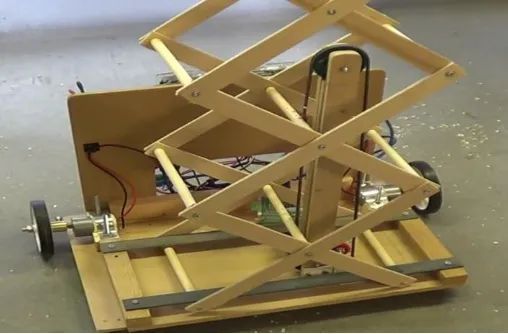
Now, in term of our design we just style a prototype for save our asset and cost of examination work and initial cost of invention. With the help of cad we just save the extreme amount to generate the cad modal and analysis it in the computer and make it accurate and well-matched. We just make our prototype with the help of wood it’s just a model. It means that it’s a future of our products.
Figure-3 :( prototype made of wood)
2. OBJECTIVES
[image:2.595.36.291.258.372.2] [image:2.595.308.562.342.509.2]
As job to be lifted are heavier which causes more distortions in hydraulic lift frame checking deformations & tensions induced in it is a major objective.
Weight of the Current lift is high; Weight optimization by modifying existing design is also prime objective of this project.
As loading & unloading is recurrent there may be chances of fatigue failure, to check the life of lift.
To check vibration of hydraulic lift during occupied time by modal analysis.
3. Material Selections
After thorough survey regarding the strength and economics of different materials, it was found out that mild steel (MS) is the most appropriate material for the construction of the unit. MS IS used at top of platform for support and to have better look to the equipment. Also Aluminum sheet of 3 mm thickness is used at top as material for platform. Aluminum sheet of 3 mm thickness is used at base. Material selection plays a very important role in machine design. For example, the cost of materials in any machine is a good determinant of the cost of the machine. more than the cost is the fact that materials are always a very decisive factor for a good design. The best of the particular material for the machine depends on the particular purpose and the material for the machine depends on the particular purpose and the mode of operation of the machine apparatuses. Also, it depends on the expected mode of failure of the components.
Table 1: Chemical configuration of mild steel
It is necessary to evaluate the particular type of forces imposed on components with a view to determining the exact mechanical properties and necessary material for each equipment. A very brief analysis of each component follows thus:
I. Scissors arms II. Hydraulic cylinder III. Top plat form IV. Base plat form V. Wheels
3.1Scissors Arms: this element is subjected to buckling load and bending load tending to break or cause bending of the components, hence based on strength, stiffness, plasticity and hardness. A recommended material is stainless steel/ mild steel.
3.2 Hydraulic Cylinder: this element is considered as a strut with both ends pinned. It is subjected to direct compressive force which imposes a bending stress which may cause buckling of the component. It is also subjected to
internal compressive pressure which generates circumferential and longitudinal stresses all around the wall thickness. Hence necessary material property must include strength, ductility, toughness and hardness. The recommended material is mild steel.
3.3 Top Platform: this element is subjected to the mass of the vehicle and material, hence strength is required, the frame of the plat form is mild steel and the base is mild steel.
3.4 Base Platform: this element is subjected to the weight of the top plat form and the scissors arms. It is also responsible for the stability of the whole assembly, therefore strength. Hardness and stiffness are needed mechanical properties. Mild steel is used.
3.5 Wheels:the wheels are position at the base part of the scissors lift and enable the lift to move from one place to the other without necessary employment of external equipment like car.
4. Methodology:-
Bend in scissors lifts can be defined as the change in elevation of all parts to the original size of entire assembly i.e. from the floor to the top of platform deck, whenever loads are applied to or removed from the lift. Each element within the scissors lift has the potential to store or release energy when full and dropped. Deflection takes place in all parts of scissor lift i.e. Scissors Legs, Platform Structure, Base Frame, and Pinned Joints. To decrease stresses and deflection in scissor lift the load should relocation equally between the two scissors arm pair. Base frames should be involved to the surface on which they are mounted.
Figure4: methodology
Carbon Silicon Manganese Sulphur Phosphorous
4 FINITE ELEMENT METHOD:
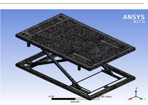
By using solid work (2014), NX UNIGRAPHIS, modeling of scissor lift was complete and then it was imported to Ansys17.0 for the analysis of scissor lift. The objective of meshing in ANSYS Workbench is to deliver robust, easy to use meshing tools that will shorten the mesh generation process. In this hydraulic scissor lift automation meshing is applied and complete analysis of scissor lift was done.
4.1 MODELING: All the parts of scissor lift which necessity is designed and assemble are given below:
Figure5: modeling
4.2 Modeling of Hydraulic scissor lift in ANSYS software: In this section, ANSYS model for Hydraulic Scissor lift are discussed. First step is to go through the ANSYS Workbench.
In second stage go through the static structure Then click to engineering data and then input the
properties of related material
After completion, go to the geometry click and again go to import geometry, then go to model click After Import the geometry, then generates the mash
for following models.
After mesh generates the go through Static Structural and input the support and force are applied in the following, such hydraulic scissor lift model.
After loads are assigning then a solution may be obtained.
4.3 FEA MODEL: The mesh influences the accuracy, convergence and speed of the solution. Below figure shows automatic type of triangular meshing.
[image:4.595.308.567.65.249.2]
Table2 : FAE analysis data
Figure 6: meshing in ansys
4.4 STATIC ANALYSIS OF HYDRAULIC LIFT:
Procedure For Static Analysis in ANSYS:
1. Build the FE model as explained in above section 2. Describe the material properties such as young's modulus and density etc.,
3. Put on boundary condition and pressures.
4. Solve the problem using current LS command from the tool.
4.5STATIC ANALYSIS OF MS LIFT:
Properties of MS Lift: 1. Young’s modulus E= 210 MPa 2. Poisson’s ratio NUXY=0.303 3. Mass density =750 kg/m3 4. Damping co-efficient =0.008
Figure7: final analysis result
5. CONCLUSIONS:
By analyzing the results obtained after experimentation, software analysis and theoretical calculations, we find that for the hydraulic lift which is use as an vehicle jack or as an use of material loading and unloading purposes which is easy to use and easy to maintain and the material used in manufacturing of scissor lift is mild steel and its help to
No. of Nodes 168431
reduce cost and increase life of the lift or strength of lift the deformation of lift is low.
1. Mass of the hydraulic scissor lift optimized on modifying existing design.
2. As loading and unloading is repeated fatigue failure is checked and hence life of the hydraulic scissor lifts. 3. Deformations made in MS lift are less
4. On transforming the design of lift i.e. reducing thickness of ribs, plates, and adding proper channels for the support as described in section, strength and mass of the lift optimized.
5. As natural frequency of modified lift does not match with external excitation frequency hence any vibrations. 6. After adaptation of lift failure at surface as shown in
problem statement get minimized.
6. Testing and Results:
[image:5.595.34.303.418.602.2]
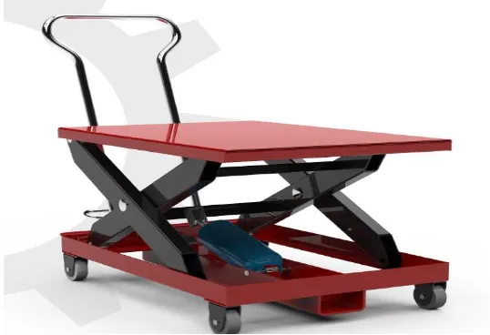
The final prototype was assembled and tested for proper function. Because this prototype had some obvious defects, detailed tests of mechanical strength were not possible. Rather, testing involved using the hydraulic system to raise and lower the platform to various positions under different conditions and observing the performance of the system. The analysis on dimensions can be performed for same material, weight, and dimensions, buckling, and bending strength.
Figure 8: final modal
REFERENCES:
1. Todd J. Bacon“Belt-driven transportation system” (2014).
2. Arturo Valencia Ochoa Jaime Antonio Uribe “Scissors lift platform with electronic control”(1997)
3. Donald Watkins“Scissor lift mechanism” (2004).
4. Enoch L. Newlin “Scissor lift mechanism employing telescopable electro-mechanical based lift actuation arrangement”(2000).
5. Mahmood Ronaghi, John Z. Wu, Christopher S. Pan, James R.
6. Harris, Daniel Welcome, Sharon S. Chiou, Brad Boehler and Ren G. Dong“An initiative to model static stability”(2009) .