© 2017, IRJET | Impact Factor value: 5.181 | ISO 9001:2008 Certified Journal
| Page 943
Compare Coated and Simple Cutting Tool, for Optimized the Surface
Roughness of Composite Material-Alloy Steel 316I in CNC Machine
1
Prof. Chandresh Rana,
2Bhavesh K Mishra,
3Nihir Patel,
4Kshatriya Abhishek
1
Assistant Professor, Dept. of Mech Engineering, Vadodara Institute of Engineering, Gujarat, India
234
B.E Student, Dept. of Mech Engineering, Vadodara Institute of Engineering, Gujarat, India
---***---Abstract -
It has set up those prior surface coatings on any cutting tools to get better wear resistance by causing the transformation to the contact conditions between the chip and tool interface. As from the recent development, coated tools have made a primary contribution to the all type of metal cutting operations in terms of life span of tool, cutting time and quality of machining.The mechanical containing properties of TiN, TiAlN, are to be compared with the uncoated Tungsten carbide cutting tool. Same as different type of processes like Chemical Vapor Deposition and Physical vapor Deposition Methods could be used as comparatively. Also the present work till now would use to find the best coating that has to be done on the base materials and also to calculate the life of tool.Key Words: TIN, TIAlN, PVD, Surface roughness, Temperature guage
1.INTRODUCTION
Cutting Tools these days are appropriate and do give good quality, but there is a need to develop the coatings to be done on the cutting tools for the sake of accuracy and quality. While the cutting operation, tool often faces issue of wear between chip and tool interface, thus the cutting tools are required to be specially coated, so that the appropriate quality, surface finish as well as wear resistance is obtainedCoated cutting tool should have various properties so that tool can be withstand for a long time while performing the operation and machining continuously without breakage of tool or any harm to the work piece. Tool should have properties such as high cutting speed, long tool life, and more wear resistance and can be work under higher temperature.
1.1 Problem Identification
We are focusing on to maintaining hardness, strength, and wear resistance in a cutting tool at elevated temperatures. This property ensures that the tool does not undergo any failure and thus retains its shape and sharpness.
Toughness and impact strength (or mechanical shock resistance), such that impact forces on the tool that are encountered repeatedly in interrupted cutting
operations or forces due to vibration and chatter during machining do not chip or fracture the tool.
(1) Surface finish
(2) Wear resistance
(3) High cutting speed
(4) More accuracy
1.2 Scope of future work
Thermal Shock resistance to withstand the rapid temperature cycling encountered in interrupted cutting. Wear resistance so that an acceptable tool life is obtained before replacement is necessary. Chemical stability is also needed to avoid or minimize any adverse reactions, adhesion, and tool-chip diffusion.
We are planning to do following type of coatings with the collaboration from industries:
Titanium Carbo-Nitride (TiCN) Titanium Nitride (TiN)
Aluminum Titanium Nitride (AlTiN) Zirconium Nitride (ZrN)
Nickel Chrome Black Oxide Diamond
2. METHODOLOGY AND MATERIALS
2.1 Coating MethodsCoatings thickness of 2-15 μm, are applied on cutting tools and inserts by the following techniques:
1. Chemical-vapor deposition (CVD), including plasma-assisted
2. Physical-vapor deposition (PVD)
Coatings for cutting tools, as well as Punches and Dies , should have the following general characteristics:
1. Higher hardness at elevated temperatures 2. Chemical stability to the work-piece material
3. Lower bonding to the substrate to prevent flake or spalling
© 2017, IRJET | Impact Factor value: 5.181 | ISO 9001:2008 Certified Journal
| Page 944
Honing is one of the cutting edges is an important procedure for the maintenance of coating strength; otherwise, the coating may peel or chip off at sharp edges.
2.1.1 Coating Materials
Coating technology is one means of achieving a crucial enhancement in tool performance. However, there is such a huge variety of available coating materials, coating structures and coating processes that careful selection of a suitable coating system is essential. Using accessible know-how concerning coated cutting tools and their behaviour in a wide range of different machining tasks, evaluating and influence the properties of tool coatings.
Coatings which are done are : TiN,TiAlN on Carbide end milling cutter.
2.2 Work-piece Material
Up to now, little attention has been paid to gaining an understanding of the influence of the workpiece material in machining. Work piece material plays a vital role while performing the choice of cutting tools. According to the need of work-piece and hardened the cutting tool is selected.
Alloy Steel ( Grade: 316)
Alloy 316/316L (UNS S31600/ S31603) is a chromium-nickel-molybdenum austenitic stainless steel developed to provide improved corrosion resistance to Alloy 304/304L in moderately corrosive environments. It is often utilized in process streams containing chlorides or halides. The addition of molybdenum improves general corrosion and chloride pitting resistance. It also provides higher creep, stress-to-rupture and tensile strength at elevated temperatures.
2.3 OPERATING MACHINE
The machining is to be operated on the specific machine in which we have to perform the task. Although finishing and surface roughness is totally dependent on what type of machine do you use. It means that finishing will be much more better in VMC machine compare to vertical milling machine , Same way the turning would be much better than lathe turning. In our project we had used VMC and CNC lathe machine to perform operation.
2.3.1 Vertical Milling Machine (VMC)
Milling is the one which is most used in metal removing in company and milling surfaces are used largely to merge with other parts in aerospace, die, and machinery design also in machining industry. One of the most important factor is surface roughness of production quality and influence the optimum machining cost. The mechanism which is behind the formation of surface roughness is very complicated dynamic and dependent on; it is too difficult to calculate and find the surface roughness value by theoretical analysis
.
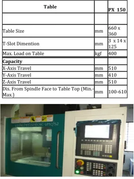
2.3.2 Specification
Fig-1 VMC MACHINE
2.3.4 Temperature Measurement
1. Cutting temperature of CFRP was measured by the tool-workpiece thermocouple method. 2. The cutting point temperature exceeded the
glass-transition temperature.
3. Temperature of machined surface layer was measured with an embedded thermocouple. 4. Temperature of machined surface layer decreases
steeply as apart from the surface.
5. SEM observation of machined surface revealed that the matrix resin was not damaged.
Fig-2 Temperature measurement device
Table PX 150
Table Size mm 660 x 360
T-Slot Dimention mm 3 x 14 x 125 Max. Load on Table kgf 400
Capacity
X-Axis Travel mm 510
Y-Axis Travel mm 410
Z-Axis Travel mm 510
Dis. From Spindle Face to Table Top
[image:2.595.308.573.129.481.2]© 2017, IRJET | Impact Factor value: 5.181 | ISO 9001:2008 Certified Journal
| Page 945
2.3.5 Surface Roughness
Roughness plays an important role in determining how a real object will interact with its environment. Rough surfaces usually wear more quickly and have higher friction coefficients than smooth surfaces (see tribology). Roughness is often a good predictor of the performance of a mechanical component, since irregularities in the surface may form nucleation sites for cracks or corrosion. On the other hand, roughness may promote adhesion.
Fig-3 Surface Roughness tester (SF101)
3.
OBSERVATION TABLE AND RESULT
3.1 Way of Conducting the Experiment :-
This is the operation and machining process which we had done in this project. While performing the experiment on the VMC we had done the operation by keeping coolant off and coolant off that is nothing but the dry and wet process. Also we had taken the parameters which are D.O.C, Feed, R.P.M, Surface roughness, Temperature.
After the end of the experiment we would conclude that which coating was the best while giving the best surface finish and whether we get finishing while keeping coolant off or coolant on.
The Experiment was conducted in two ways that is with Coolant and without coolant so result will be different for both.
3.2 END MILLING OPERATION
Fig-4 Work-piece material Alloy steel 316I
3.2.1 Observation Table :
Table-1 Observation table
3.3 CNC MILLING (DRY)
In this CNC Milling norm operation this the dry process in which we had kept the coolant off. In this we had taken the surface roughness and also the temperature of the tool and work-piece at the interference. Basically the experiment was performed on the ALLOY STEEL 316 I hardened metal and the tool which we used are of 4 types that are stated in the observation table.
We had performed this in by giving the different R.P.M , Feed and D.O.C as we have taken 6 readings for different R.P.M Feed and depth of cut and that too by keeping coolant off and dry we have slotted 48 slots for this experiment on the work-piece .
Below is the experiment observation table and graph of the parameters which we had taken for the result perspective and variance effects to come from the result and graph.
© 2017, IRJET | Impact Factor value: 5.181 | ISO 9001:2008 Certified Journal
| Page 946
perspective we have taken the four coating materials and we are concluding the best amongst the four. In taguchi method only the result which would come out is only amongst the best of one coating. We cant compare all the four coating.
Where, Series 1 – H.S.S, Series2- Carbide end milling cutter, Series 3 – TiN coated Carbide End milling
Series 4- TiAlN coated End milling cutter
Table-2
Chart-1 : R.P.M – SURFACE ROUGHNESS
Chart-2 : FEED – SURFACE ROUGHNESS
3.3.1 RESULT
As we have taken first of all the two parameters that are Surface roughness and R.P.M. As we know that the rotation per minute makes the lot of affect to the workpiece cutting material. Also it affects the temperature.
As from the graph it can be easily concluded that the Surface roughness can be easily available at the greater R.P.M. Also it depends sometimes on the heating which is produced at the interference of the tool and work-piece.
H.S.S – We can see that the better surface roughness we are getting at the highest R.P.M that is at 4000 r.p.m and feed 500 mm/min we get 1.69 micron m Surface roughness.
CARBIDE – As from the table and from the graph it can be easily known that the at 4000 r.p.m and feed 500 mm/min we get the surface roughnes 1.49 micron m that is the good surface finish we have obtained in the Carbide.
CARBIDE TiN COATING – This is the PvD coated tool in which we have got the surface finishing more accurate than the H.S.S and Simple Carbide. In this we have obtained the best Surface roughness at the lowest r.p.m that is on 2000 r.p.m and feed 250 mm/min we get the 1.29 micron surface roughness that is very good finishing.
CARBIDE TiAlN COATING – As compare to all the H.S.S and Simple Carbide and Coated TiN carbide we have got the best result for the surface finish in the TiAlN coating.This coating was proved as the most liable and better coating for the surface roughness and finishing compare to other coated and simple tools which were used in this experiment. At 3600 r.p.m and feed 450 mm/min we got the 0.89 surface finish which was the best amongst all the coating.
. END MILLING – CONSTANT R.P.M \ VARIOUS CUTTING
TOOL SURFACE ROUGHNESS CHART (DRY) \ FEED
R.PM FED SIMPLE
H.S.S
SIMPLE
CARBIDE TiN COATED CARBIDE
TiAlN COATED CARBIDE
2000 250 1.71 1.6
7 1.29 1.2 2
2400 300 1.76 1.6
2 1.38 1.1 9
2800 350 1.79 1.6
4 1.52 1.1
3200 400 1.81 1.5
9 1.49 1.0 8
3600 450 1.72 1.5
5 1.5 0.8 9
4000 500 1.69 1.4
© 2017, IRJET | Impact Factor value: 5.181 | ISO 9001:2008 Certified Journal
| Page 947
3.4 CNC MILLING (WET)
Here in the Graph its shows the result and relation between the Feed → Surface Roughness and another one is of R.P.M → Surface Roughness from which can conclude that which coating would be the most suitable.
Actually in these perspective we have taken the four coating materials and we are concluding the best amongst the four. In taguchi method only the result which would come out is only amongst the best of one coating. We cant compare all the four coating.
Where, Series 1 – H.S.S, Series2- Carbide end milling cutter, Series 3 – TiN coated Carbide End milling
Series 4- TiAlN coated End milling cutter
Chart-3: R.P.M – SURFACE ROUGHNESS
Chart-4 : FEED – SURFACE ROUGHNESS
3.4.1 RESULT
H.S.S – We can see that the better surface roughness we are getting at the highest R.P.M that is at 4000 r.p.m and feed 500 mm/min we get 1.15 micron m Surface roughness.
CARBIDE – As from the table and from the graph it can be easily known that the at 4000 r.p.m and feed 500 mm/min we get the surface roughnes 1.06 micron m that is the good surface finish we have obtained in the Carbide.
CARBIDE TiN COATING – This is the PvD coated tool in which we have got the surface finishing more accurate than the H.S.S and Simple Carbide. In this we have obtained the best Surface roughness at the lowest r.p.m that is on 2000 r.p.m and feed 250 mm/min we get the 1.14 micron surface roughness that is very good finishing.
CARBIDE TiAlN COATING – As compare to all the H.S.S and Simple Carbide and Coated TiN carbide we have got the best result for the surface finish in the TiAlN coating.This coating was proved as the most liable and better coating for the surface roughness and finishing compare to other coated and simple tools which were used in this experiment. At 3600 r.p.m and feed 450 mm/min we got the 0.82 micron surface finish which was the best amongst all the coating.
CONCLUSION
As the above observation table shows the different coating performance on different cutting tools and work-piece.
We have Machining Process that is End milling in which we have used in milling Carbide and HSS cutting tool with 2 coating and 1 simple tool and 1 HSS tool
© 2017, IRJET | Impact Factor value: 5.181 | ISO 9001:2008 Certified Journal
| Page 948
REFERENCES
[1].
Weiguang Zhu “TiN coating of tool steels: a review” published by JAMPT journal :[2].
http://nanocoating.ir/en/wp- content/uploads/2014/12/TiNcoating-of-tool-steel.pdf
[3].
Anakkavur T. Santhanam “Method of machining coated cutting tool” on JULY-1994 :https://www.google.com/patents/US5325747[4].
T. Krieg “Coated Tools for Metal Cutting – Featuresand Applications” by ELSEVIER https://www.researchgate.net/publication/245226 743_Coated_Tools_for_Metal_Cutting_features and application.