© 2017, IRJET | Impact Factor value: 6.171 | ISO 9001:2008 Certified Journal | Page 1610
Design and Implementation of FTTH
Manojkumar Lokhande
1, Amarjeet Singh
21
Senior Executive-FTTx Planning, Reliance Jio Infocomm Limited, Pune, Maharashtra, India
2State Manager -Intracity Fiber Planning, Reliance Jio Infocomm Limited, Pune, Maharashtra, India
---***---Abstract –
The telecommunications scape has matured to apoint that carriers look up to offer network convergence and enable the revolution of consumer media device interaction. These demands are being met by the deeper penetration of optical fiber in access networks and increasing deployment of fiber to the home (FTTH). As a result, FTTH is the fastest growing global broadband technology with significant deployments occurring in India. It is technology that provides
future proof of bandwidth
.
The main aim of the paper is optimized network and
reduce the cost of fiber optic component.This paper presents a
step by step design and field implementation of a protected Gigabit Passive Optical Network (GPON) FTTH access network by using GIS and AutoCAD. Design incorporate class B protection to provide redundancy in the feeder and GPON port, the practical implementation of a protected FTTH network is highly emphasized. Now a day GIS (Geo-graphic Information System) is widely used to plan, build, design, and operate telecommunication networks and associated services. GIS based fiber tool provides more accurate planning for new fiber network and seamless management of the entire integrated infrastructure. The basic components of the network are presented and the contribution of each component to the architecture of the FTTH network is addressed. FTTH provides all types of services voice, video and data over common IP protocol.
Key Words: FTTH, GPON, AutoCAD, ArcGIS, Network Planning.
1.
INTRODUCTION
FTTH means fiber to the home or fiber to the Premises, In last ten years, the bandwidth required for services such as High Definition TV and Internet has grown explosively. In this, many telecommunication carriers are already realizing FTTH projects, and in addition, many companies are seriously investigating how such a network could be deployed. This has made possible transmit and receive data from computer networks, TV programs, interactive video, and conventional telephone at greatly reduced hardware and cost.
Aim of this paper is to introduce a new methodology that identifies the optimization deployment using GIS and AutoCAD based network design. GIS is a system designed to capture, store, manipulate, analyze, manage, and present all types of geographical data.
FTTH is basically deployed in 2 basic specific configuration In P2P, one fiber is dedicated to every user in whole network. There is no shearing of bandwidth or fiber, including active devices. While in PON, fiber and bandwidth are shared among group of users. The deployment of FTTH network is an expensive task, and it needs good planning of POP (Point of Presence) and pre-knowledge about the roads, river and other public network infrastructures for the region covered by FTTH. To save time and money, the GIS environment can be used for analyzing and preparing the required data easily within very short timelines and highly accurate.
GPON stands for Gigabit Passive Optical Networks. GPON is defined by ITU-T recommendation series G.984.1 through G.984.6. GPON can transport not only Ethernet but also ATM (Asynchronous Transfer Mode) and TDM (time division multiplexing) traffic. GPON uses optical WDM so a single fiber can be used for both upstream and downstream data. In downstream direction, data packets are transmitted in broadcast manner while in upstream direction, data packets transmitted in TDMA manner. Voice, data, and digital video will be delivered as ATM technology using TDM based on the baseband digital approach. WDN (Wavelength division multiplexing) or a λ - based structure technique significantly increases the transmission capacity of optical fiber by enabling signals with different wavelengths to be transmitted together along the same fiber.
BPON, which was really the first type of PON used in United States, it is used for simple voice and data. The BPON is mainly analog. GPON is the upgraded version of BPON. It also provides the facility of video streaming like cable TV. GPON is a totally digital system by going to IP-TV with digital voice and data. EPON is advance system which is working on Ethernet instead of using an ATM protocol.
Table-1: TDM PON standards
© 2017, IRJET | Impact Factor value: 6.171 | ISO 9001:2008 Certified Journal | Page 1611
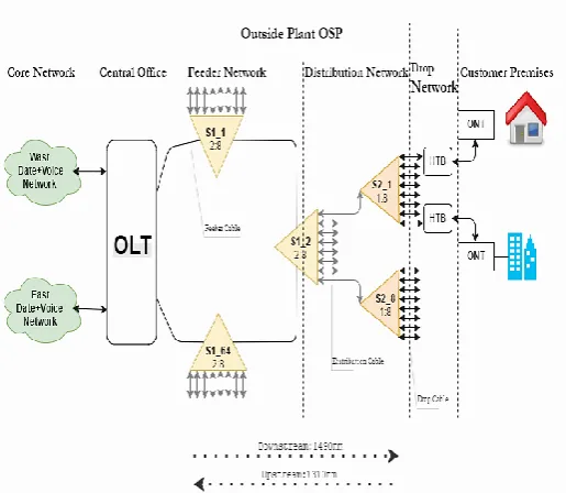
(FP) laser diode (LD) is preferred as the transmitter at the optical network units (ONUs) because of its lower cost compared to distributed feedback (DFB). In GPON network mainly two active transmission equipment’s, namely- Optical Line Termination (OLT) and Optical Network Unit (ONU) or Optical Network Termination (ONT) while all others equipment’s are passive transmission equipment namely S1 & S2 splitter and HTB. The operating wavelength range is 1310 nm for upstream and 1490 is for downstream. Upstream is direction from signals flowing from the ONT(s) to the OLT and downstream is direction from signals flowing from the OLT to the ONT(s);
Mainly there are two of splitting stage centralized and cascaded, in centralized approach use only single splitter while in cascaded use multiple splitter.
2.
ARCHITECTURE
The main aim of this architecture is to minimize the amount of optical cable length that is needed for the distribution and drop fibers, which provides a low cost of the outside cable plant when implementing a FTTH network.
Fig -1: Basic Architecture of FTTH
ODF is located at OLT site which is used to terminate assigned fiber on feeder cable, distribution cable and S1.OLT should have the high capacity, high reliability and high density. FTTH network provides two types of services like voice over IP (VoIP) and High Speed Internet (HSI). Selection of OLT site is depends on required power, available space and 24*7 accessibility. OLT site shall be manage with 2 feeder rings and distribution points are equally divided in FSA boundary. From one OLT, we can provides service to 4096 HP or ONT connections. 2:8 splitter is considered as S1 and 1:8 splitter considered as S2 splitter. Fiber Access Terminal
(FAT) will be used for S2 location. . Feeder cable used as interface with ODF and S1. Distribution cable is in between S1 and S2 splitter
.
3.
DESIGN STEPS
The Design of an FTTH access network is one of the challenging part; it needs to reduce different factors including size, cost, and scalability. Land base data means home pass (HP) count (No. of flats, No. of shops, No .of commercial), road network and building polygons verification in GIS server. Road network as straight center lines. Need to create project area manually with consideration of OLT capacity and HP count, crossing of rail track and national highway, water body, distance from OLT to ONT, etc.
In field survey, the data collection should be checked for accuracy and integrated with the existing low level design map which will then be used as a basis for planning the OLT ring on FTTx route. OLT site feasibility, Building captured data, and feeder route as per construction proposal should be more accurate. There can be change in the stated lengths as per design requirement and variation of upper limit of +10% should be covered in the bid.
1. First decide PoP (Point of Presence) boundary which has one OLT location site which east and west side must be traced to core network. POP boundary does not exceed more than 2700 HP count. Try to Keep OLT location at center location of that boundary. 2. After creating PoP, boundary will reflect in AutoCAD.
Clean all unwanted road network and building existing pipes (planned route), then create possible trench and building entry point. Tool will create the building entry points on every building based on the building polygons and will move the point to the closest possible trench. Tool automatically calculated shortest path between building entry point to possible trench.
3. After this define some design rules for feeder distribution and drop like capacity of FSA, DSA & CSA boundary and length of feeder, distribution and drop cable. In design rule also define cost of equipment tool automatically created bill of material (cost per building, cost per home and checkbox) 4. Then create FSA clustering, In PoP may have more
than one eNodeB location then move OLT location on selected eNodeB location.
5. Do S2 calculation step, it will create CSA boundary, FAT, drop cable and drop points, we can modify CSA then lock all CSA boundary and drop points. 6. Do S1 calculation step, it will create DSA boundary,
[image:2.595.37.295.384.608.2]© 2017, IRJET | Impact Factor value: 6.171 | ISO 9001:2008 Certified Journal | Page 1612
can modify DSA then lock all DSA boundary and distribution points.
7. Calculate feeder calculation, as per define rule feeder ring will create automatically or as per requirement do manually feeder ring.
As per default feeder ring is calculated automatically, keep created ring for reference then change in rule and manually modify feeder ring. But distribution points and home pass mast have keep 4:6 ratio.
4.
GIS And AutoCAD
A GIS based fiber tool provides more accurate planning for new fiber network and seamless management of the entire integrated infrastructure. GIS have been used to determine the most suitable method of transmission (wireless or cable), plan network layouts, and target customers. However, with development of computer and software, it is possible now tracking any fault and determining its location easily. By knowing the coordinates, the troubleshooting team will find the defect quickly and fix it. In GIS we know three different ways: in terms of a database (database view), the map (map view) and model (model view). ArcGIS latest version 10.2 is released and available in the market.
AutoCAD is help for build, test and maintain the FTTH network and also for creating an accurate Bill of Materials (BoM) and Bill of Quantity (BOQ). BOM generates outside plan, head end, and premises equipment and labor cost with enhanced reach and split ratio and estimate cost as associated with passive and active equipment and components for the typical FTTH network. Automatically CAD creates ODN (optical Distribution Network) plan, civil plan and spice plan. ODN provides the physical channels from OLT and ONT to communicate with each other. Splice plan generates with each joint chamber, S1 splitter, FSA and DSA. Tool is used for designing of high level network design. It also creates fiber schematics and in building schema and splice plan schema. Fiber PlanIT saves time, saves on deployment costs and is really easy to use. There is no room for human errors.
Splitter:
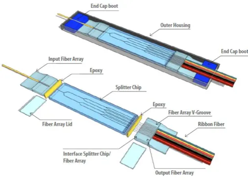
There are 2 types of splitter commonly used for passive optical network, FBT (fused biconical taper) and PLC (Planner Lightwave Circuit). This optical power management device is fabricated using silica. It has small in size and high reliability. PLC splitter works with single mode fiber at wavelength range from 1260nm to 1650nm.
Fig -2: PLC Splitter
There are three main components which are splitter chip and the fiber array for the input and output, and the chip.PLC splitter has low failure rate as compaired to FBT Splitter.FTB has have a low cost but its operating range is restricted.
The PON splitter should have the following characteristics
Broad operating wavelength
Minimum dimension
Uniformity in any conditions and low insertion loss.
It is connected to central office using single-mode optical fiber wire. The power level for each subscriber can be easily calculated, dividing the optical power entering the splitter (P) by number of path (N).
There are 2 major topology for splitter one is centralized and another is cascaded splitting. In centralized topology, there is only one throughput and in cascaded topology, GPON is done twice throughput using the ODN network. In each feeder ring 32 S1 can be planned.S1 should be in joint closure and in Fiber Distribution Cabinet (FDC).FDC is designed especially for GPON architectures because one fiber coming in goes into a splitter, usually in a tray then breaks out to as 8 different S2 splitter. So the management of the patch cords form the S1 splitter to the S2 splitter.
When there is HP count is more than 50 in single building then S1 is placed in FDC. Maximum 2-S1 will be placed in one FDC. Joint closure is used where distribution serve single dwelling units (SDU). S2 should be in Fiber access Terminal) or in OTB (Optical Terminal Box) for MDU (Multi dwelling units) scenario. 2-S2 will be placed in one FAT. Feeder Path can be split up to 64 path.
[image:3.595.313.567.102.289.2]© 2017, IRJET | Impact Factor value: 6.171 | ISO 9001:2008 Certified Journal | Page 1613
and ONU. OLT should be installed in central office (CO) in standard rack with termination at front side. OLT is a device which serves as the service provider endpoint of a passive optical network. It provides two main functions:
To perform conversion between the electrical signals used by the service provider’s equipment and the fiber optic passive component signals used by the passive optical network.
To coordinate the multiplexing between the conversions devices on the other end of that network (called either optical network terminals or optical network units).
It operates on -48V DC power. Nokia 7360 FX series supports GPON technology. In market, OLT is available in three size variants (FX-4, FX-8 and FX-16). OLT FX-4 has 4 LT (Line Terminal slots) each is having 16 PON ports and 2 NT (Network Terminal).
OLT obtains the Round Trip Delay (RTD) through ranging process, then specifies suitable Equalization Delay (EqD) so as to avoid occurrence of collision on optical splitters. RTD is the length of time it takes for a signal to be sent plus the length of time it takes for an acknowledgment of that signal to be received. The ONT terminates the FTTH optical network at the subscriber premises and includes an electro-optical converter. ONT takes the optical signals coming from the central office through the splitter and converts them into video, voice and data in the home over the conventional types of cables that you expect. Coaxial unshielded twisted pair for video, CAT-5 for the computer and copper pair for the telephone service. ONT is basically a media converter and using different wavelengths is able to transmit and receive simultaneously and one single mode fiber digital information corresponding to voice, data and video.
5.
Fiber Optic Cable Implementation
Fiber optic cable refers to the complete assembly of fibers, strength members and jacket. Fiber optic cables come in lots of different types, depending on the number of fibers and how and where it will be installed. Choose cable carefully as the choice will affect how easy it is to install, splice or terminate and, most important, what it will cost. Optical fiber has basically two types of modes-Single mode and Multimode. Single mode fiber is used in FTTH because multimode fiber does not support necessary distances and speed. Single mode fiber has higher carrier bandwidth than multimode fiber. Single mode fiber has small dimensional core than multimode.
Feeder Cable: Feeder Cable provides the highest package density. Single mode fiber is used for FTTH network feeder design. The cable choices for feeder rings are 48F (Loose Tube, 6 Fiber X 8 Buffers) and 12F (2 Fiber X 6 Buffers). Feeder cable is extended using other 12F cable till buildings
entry point. This route shall be considered as feeder path and FDC with S1 splitter is installed inside building. Out of 48 Fiber, 30 Fiber will be used for S1, 6 Fiber is allocated for spares and 12 Fiber is reserved for future enhancement. Feeder ring should not exceed more than 4km.
Distribution Cable: It provides the less package density then feeder cable. Distribution cable is intermediate cable for connecting the feeder cable subsystem and the drop cable subsystem. 6F and 12F is used for distribution cable. In 12F distribution fiber, 8F is used for S2, 2F is allocated for spares and 2F is reserved for future enhancement and in 6F (3 Buffer X 2F) distribution, 4F is use for S2 splitter, 1F is allocated for spares and 1F is reserved for future enhancement. 12F cable is used when there is more than 8 S2 Splitters (64 Homes) coming on Distribution Segment and 6F cable is used when there is 4 S2 Splitters (32 Homes) coming on Distribution Segment. Distribution cable should not exceed more than 400m
.
Drop Cable: These are small in size, very short. Drop cable is 1F/2F which is in between FAT to ONT (customer premises). 1F is for indoor drop and 2F is for outdoor drop. Drop cable should not exceed more than 50m. Length of each piece of feeder cables and distribution cables are mentioned in design rules, as well as the distance between two manholes, distance between FAT and manhole and the distance between two FATs. OTB (Outdoor Terminal Box) is used when drop cable length between ONT and drop point is more than 50m. OTB works as a repeater where more number of HP is on same floor. In order to provide FTTH services to customers at affordable prices, it is necessary to reduce both the cost of optical access systems and the expenses associated with the installation of optical fiber and associated hardware by simplifying the installation of optical drop cables, optical cabinets, and indoor wiring.
As per class B+ standard, GPON optical transmission works only if optical threshold of total losses between -15 to 25dBm. ONT provides services only between specified ranges of power. If loss is less than 15dB power then attenuator is used for ONT.
6.
Fiber attenuation
Loss budget calculation is also important for proper implementation. Loss budget includes fiber attenuation (length) of feeder, distribution and drop, splicing loss, adopter loss, S1 and S2 splitter loss, connector and engineering safety loss.
The power received at the ONT side at the receiver premises is calculated by:
∑ (Power input) = ∑ (Power output of all branch)
© 2017, IRJET | Impact Factor value: 6.171 | ISO 9001:2008 Certified Journal | Page 1614
Generally loss can be summarized by the equation
𝑙𝑜𝑠𝑠 = 𝑙𝑐𝑎𝑏𝑙𝑒 + 𝑙𝑠𝑝𝑙𝑖𝑡𝑡𝑒𝑟 + 𝑙𝑠𝑝𝑙𝑖𝑐𝑒 + 𝑙𝑐𝑜𝑛𝑛𝑒𝑐𝑡𝑜𝑟
Worst case loss = (mSµ + kCµ + LFµ + bBµ + Mµ) - σ
Where,
m = number of splices; k = number of connectors; L = fiber length (km);
b = number of optical branching devices; Sµ = mean splice loss (dB);
Cµ = mean connector loss (dB); Fµ = mean fiber loss (dB/km);
Bµ = mean loss optical branching device (dB); Mµ = mean loss miscellaneous device (dB); σ = standard deviation loss
The Bill of Material (BOM) is required for the calculations of power budget, so that comparison could be carried out between the theoretical and practical values acquired upon physical network deployment of planned platform at selected area in Pune, India.
Table -2:Comparison of Theoretical and Practical Loss Values
Description Values (dBm) Theoretical Practical Values (dBm)
Transmission Loss 0.35 0.36 Splicing Loss 0.1 0.05 Connector Loss 0.4 0.42 2:8 splitter loss 10.2 10.27 1:8 splitter loss 10.5 10.5
Engineering 3 3
Margin
Splitter insertion loss is calculated by below mention formula
2:8 Splitter - 1 + 3.4 log2N 1:8 Splitter- 0.8 + 3.4 log2N
Note: N denotes the number of output ports.
Practical scenarios are devised to simulate the developed platform by using theoretical and practical values.
7.
CONCLUSIONS
This paper presented a detailed design and implementation of a type B protected GPON based FTTH access network serving 1000 users, it adopted engineering approach to emphasize practical aspects and field experience. The design procedure followed a bottom top approach, in which the size of the network and its components is defined after analyzing
the requirements, the number of locations, the geographical separation and the available infrastructure.
The current focus of research and development is on servicing a range of user demands and reducing regional disparities in service levels. We discussed optical access technology for broadband services in the form of the GPON system, installation technology, and wireless access technology. Such factors as the increasing interest in high-volume applications including Internet.
ACKNOWLEDGEMENTS
We would like to show our gratitude to the NPE-FTTH, Pune team at Reliance Jio Infocomm ltd. India for sharing their pearls of wisdom with us during the course of this research. I would also like to thank Mr. Anand Naik (Planning Head) and Mr. Amarjeet Singh (State Manager-Intracity Fiber- Maharashtra Circle) of Reliance Jio Infocomm ltd, India for valuable guidance at all stage of my work.
8.
REFERENCES
[1] M. Chardy et al., “Optimizing splitter and fiber location in multilevel optical FTTH network,” European Journal of Operational Research: Elsevier B.V, pp. 430-440, May 2013
[2] Deeksha Kocher et al., “Simulation of fiber to the home triple play services at 2 Gbit/s using GE-PON architecture for 56 ONUs,” Optic: Elsevier B.V, pp. 5007-5010, 2012
[3] Deepak Malik et al., “Quality of service in two-stages epon for fiber-to- the-home,” International Journal of Soft Computing and Engineering (IJSCE), vol. 2, No. 2, pp.387-390, May 2012.
[4] Duo Peng and Peng Zhang, “Design of Optical Integrated Access Network Based on EPON,” in proc. 2011 International Conference on Electronics and Optoelectronics (ICEOE 2011), pp. 65-68, 2011
[5] Rajneesh Kalera and R.S. Kalerb, “Simulation of Fiber to the Home at 10 Gbit/s using GE-PON architecture,” Optik: Elsevier B.V, pp. 1362-1366, 2011.
[6] Stephan Smith, “Business class services over a GPON network,” in proc. IEEE Optical Fiber Communication Conference, 2006 and the 2006 National Fiber Optic Engineers Conference. OFC 2006.