© 2018, IRJET | Impact Factor value: 7.211 | ISO 9001:2008 Certified Journal | Page 2663
1Sree L Devan, 2Deepa V S, 3Ayoob Khan T E
1MTech Student College of Engineering Chengannur,
2,3Associate Professor College of Engineering Chengannur,
---***---
Abstract - Content-addressable memory (CAM) is a special kind of search engine which is used for high speed search engine in hardware. CAM provides output typically in one clock cycle. When we consider the cost there have some disadvantages like high latency, low storage density, and low architectural scalability. In field- programmable gate arrays (FPGAs), are used in many applications. The main advantage is that it does not have hard IPs for CAM. These architectures are targeted for Ternary CAMs. Modern FPGAs are enriched with logical resources. Logic-based high performance BiCAM architecture (LH-CAM) using Xilinx FPGA. The proposed CAM is composed of CAM words and comparators. A sample of LH-CAM of size 16 × 8 is implemented on Xilinx Spartan 3 FPGA.
Key Words: Binary CAM, FPGA, higher performance, logic-based CAM, RAM-based CAM.
1 INTRODUCTION
Content-addressable memory (CAM) is a special kind of memory which is used for high speed search engine for hardware, search input data against the stored data typically in one clock cycle. In random- access memory (RAM), the search is based on contents rather than on an address. CAM has two types, based on its storing and searching ability−binary CAM (BiCAM) and ternary CAM (TCAM). BiCAM is for exact matching which stores and searches two states−0 and 1, but in TCAM, it stores and searches three states−0, 1, and don't care state. TCAM is used for partial matching. In this paper we will be discussing about BiCAM.
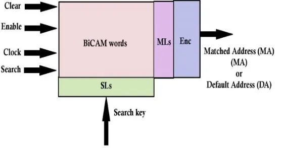
BiCAMs are designed in application-specific integrated circuits (ASIC) and it offer high speed comparison. So they are used in several applications like data encryption, cache tags, fire-walls, and Ethernet address lookup. BiCAM is composed of CAM cells arranged in a 2D array. Each cell has a static RAM cell as well as compactor. In addition to bit-lines and word-lines, CAM has search-lines (SLs) and match-lines (MLs) to support in cell comparison. MLs are fed to an encoder, which provides the matched address. A simple block diagram is of BiCAM is shown in fig 1.
[image:1.612.175.455.511.658.2]The input to the system is the search word. The search word is broadcast on the search lines. Match lines indicates if there were a match between the search and stored word. Encoder specifies the match location. If multiple matches occur the priority encoder selects the first match.
Fig.1. Block diagram of BiCAM. (ML: Match-line, SL: Search-line, Enc: Encoder).
© 2018, IRJET | Impact Factor value: 7.211 | ISO 9001:2008 Certified Journal | Page 2664
In the CAM presented in [3] works only if CAM words are ascendingly ordered. If there is any increase by a single bit in the CAM word then the memory need to be increased. If the CAM is of size 512 × 36, which cannot implemented in FPGA. RAM based CAM in [8] have some disadvantages that is the CAM technology, partitioning method is complex and also it takes longer time for the searching. Because of the traditional CAM these RAM based CAM are not implemented in FPGA. Some CAM is implemented in FPGA but they are slow and have speed of only 50 MHz. Hash based CAMs in [2] and [3] have some drawbacks that it have collision and bucket overflow. Hash based CAM uses the pre-processing method and mapping method which it makes the CAM more time consuming. Rehashing is expensive if it is implemented in hardware. For a typical RAM based CAM consumes several clock cycles, non-deterministic throughput and inefficient memory usage. In SRL 16E-based CAM consumes 16 clock cycles for the write operation which is very slow. Search latency for Xilinx CAM is lengthy and the data mapping is also time consuming it slows the table formation. RAM based CAM are typically for TCAMs and can also be used for BiCAMs. BiCAM will not reduce the memory resources when compared with TCAMs.
3 LOGIC-BASED HIGHER PERFORMANCE BINARY CONTENT ADDRESSABLE MEMORY
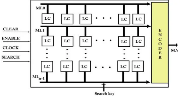
[image:2.612.160.454.396.554.2]The architecture of the binary content addressable memory is shown in Fig 2. It consists of 2D array of CAM cells. These 2D arrays are called the logic cells (LCs). Each logic cell is of one bit which contains one bit storage and one bit comparator. The RTL for single logic cell is shown in fig 3.2. For the storage D flip-flop is used and for the comparator XNOR is used. LCs in the same row is connected to the Match line (ML). LCs connected to the same ML is defined as or grouped as C-bit vector. Where C represents the total number of bits in a CAM word. The MLs are equal to the MLs in the traditional CAM. MLs are connected to the encoder (Enc). Enc is used to encode the input and gives the Matched Address (MA) as the output otherwise is gives the Default Address (DA). BiCAM is used for the exact matching so if there is any mismatch in single bit it will give the DA as the output.
Fig 2 LH: CAM Block diagram.
© 2018, IRJET | Impact Factor value: 7.211 | ISO 9001:2008 Certified Journal | Page 2665
Fig 3 RTL of single logic cell.
Fig 4 Single block diagram for LC.
A) Mapping operation
Here the portioning and pre-processing is not needed. It is much simpler and straight forward. The mapping algorithm is shown in Fig 5. This algorithm shows the mapping of a conventional CAM table to LH-CAM table. If the CAM word is of 36 bits then a 36 bit vector of FFs is required to hold the 36 bit CAM word. Example for the mapping operation is given in Table 1. From the table CW0 is mapped to V0, CW1 to V1,…CWn-1 is mapped to Vn-1. Updating BiCAM means adding or deleting the CAM
[image:3.612.191.438.448.522.2]word. Updating complexity of LH-CAM is O(1) when comparing with the previous work.
Fig 5 Algorithm for mapping operation[1]
Table 1 Example for the mapping operation from BiCAM to LH-CAM[1].
Address MLs
Typical BiCAM The LH-CAM
CAM Words Storage
vectors
0 ML0 CAM0 000101 V0 000101
1 ML1 CAM1 000111 V1 000111
2 ML2 CAM2 001111 V2 001111
© 2018, IRJET | Impact Factor value: 7.211 | ISO 9001:2008 Certified Journal | Page 2666
B) Searching Operation
The algorithm for searching operation for the LH CAM is shown in Fig 6. The input to the CAM is search key. Search key simultaneously compared with all the stored CAM words or vectors Vi where i= 1, 2, 3, …, n-1. The output will be a MA. These
[image:4.612.62.580.360.579.2]are accessed in parallel the time complexity for searching is O(1). Each logic cell has its own comparator. Search key and stored CAM words are compared by bit by bit basis. When the search key is fully matched the ML will be high. If there is any mismatch in a single bit; the match line becomes low. In the case of match MA is sent to output otherwise DA is sent to output.
Fig 6 Algorithm for searching operation[1]
C) Result and Performance Evaluation.
The BiCAM is coded in Verilog HDL. The simulation tool used is Xilinx ISE design suit 14.2. The output for the given BiCAM is shown in the Fig 7.
Fig 7 Simulation result for the BiCAM
© 2018, IRJET | Impact Factor value: 7.211 | ISO 9001:2008 Certified Journal | Page 2667
4 PROPOSED SYSTEM
A) Architecture
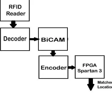
The basic architecture for the system is given in the Fig 8. RFID reader and card is used to read the book code. The specified code is given to each and every book and each code is unique. The RIFD reads the input and given to the decoder. Decoder helps to decode the value and gives the input to the BiCAM and the process inside the CAM is same as in [1]. If the book code is matched then the book location is given out through the encoder. When the book is not available it shows the non-availability of the book. The main advantage of this system is that; it is time consuming for searching the book. The disadvantage is the librarian should arrange the book according to the specified location. The search latency is one clock cycle.
Fig 8 Basic block diagram of the proposed system
The system is successfully implemented on Xilinx Spartan 6 device xc6slx9 with -2 speed. The system arrangement is give in Fig 9. The RFID module is connected to the FPGA kit. The ground pin in the RFID is connected to the FPGA ground. The transmitter pin in RFID is connected to the receiver pin in the FPGA. The 5V supply is given to the RFID module. The card value
is stored in the BiCAM. Decoder is used to converts a binary information from an n coded input to a maximum of 2n unique
outputs. Decoders are widely used in several applications like demultiplexing, seven segment display and memory address decoding. Serial in parallel out shift register (SIPO) is used to convert the data from serial format to the parallel format. Encoder is reverse to the decoder which converts 2n input to an n output. Here the priority encoder is used. According to the
priority the output is given out. The flow chart for the process is shown in Fig 10.
[image:5.612.194.379.239.394.2]© 2018, IRJET | Impact Factor value: 7.211 | ISO 9001:2008 Certified Journal | Page 2668
Fig 10 Flow Chart for the proposed system.
Universal Asynchronous Receiver/Transmitter (UART) is used to transmit and receive the data. The transmitting UART converts the parallel data to a serial to the receiving UART. In order to receive the data correctly the transmitter and receiver must agree on the baud rate. The baud rate is the rate at which the data are transmitted to the receiver. Here the baud rate is 9600 bps. The FPGA continuously samples z the line. FPGA knows whether the input is coming because the it sees the line transition from high to low. First transition indicates the start bit; if the start bit is found the FPGA waits for the half of a bit period, to sample the line.
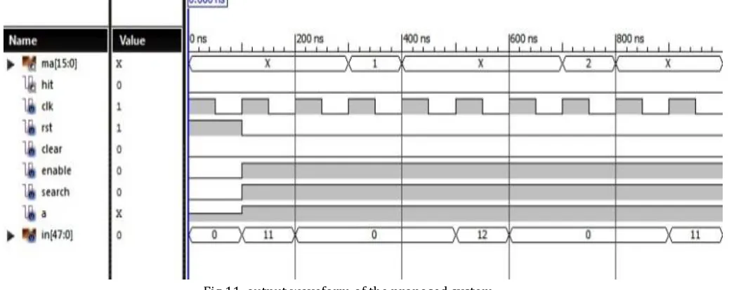
B) Performance Evaluation Result.
[image:6.612.58.577.482.689.2]The code is simulated using Xilinx ISE Design Suit 14.2 and the waveform is obtained. The output is shown in the Fig 11. When the input 11 is given as the book code. The 11 is stored in the location one. So the output is given out after two clock cycle. So the searching latency is 2 clock cycle. The 0 is not stored in the BiCAM then it shows the default address. When the book is out of stock then the hit signal become high; which indicates that the book is not available.
© 2018, IRJET | Impact Factor value: 7.211 | ISO 9001:2008 Certified Journal | Page 2669
5 CONCLUSION
The conventional BiCAM becomes more complex and slower because of the extra capacitive MLs and SLs. By this the throughput is limited by lengthy clock cycle Where for the proposed BiCAM is consist of faster vector and flexible registers. The throughput is higher. FPGA has architectural support so that it is successfully implemented. If multiple vectors are accessed in parallel to provided enough I/Os which increases the writing operation faster. If enough I/Os are available on FPGA then multiple CAM words can be mapped simultaneously. Performance evaluation shows that storage is efficient, updating the BiCAM is simpler, and preprocessing is not needed. This BiCAM is used for tracking the books in libraries so that the students or others can easily access the book. It is time consuming. The only disadvantage is that the book should be kept in the correct place. The searching and updating complexity is O(1).
6 ACKNOWLEDGEMENT
I would like to express my special thanks of gratitude to my teachers Mr. AyoobKhan T E, Associate Professor in Department of Electronics and Communication Engineering and Ms. Deepa V S, Associate Professor, Department of Electronics and Communication Engineering as well as our Principal Dr Jacob Thomas V who gave me the golden opportunity to do this wonderful project on the topic RFID based book tracking in libraries using BiCAM, which also helped me in doing a lot of Research and i came to know about so many new things I am really thankful to them. Secondly i would also like to thank my parents and friends who helped me a lot in finalizing this project within the limited time frame.
REFERENCES
[1] Zahid Ullah, “LH-CAM: Logic-based Higher Performance Binary CAM Architecture on FPGA,” in IEEE Embedded Systems
Letters 2017.
[2] P. Mahoney, Y. Savaria, G. Bois, and P. Plante, “Parallel hashing memories: an alternative to content addressable memories,”
in IEEENEWCAS Conference, 2005. The 3rd International, 2005, pp. 223–226.
[3] M. Somasundaram, “Circuits to generate a sequential index for an input number in a pre-defined list of numbers,” Patent, Dec. 26, 2006, US Patent 7,155,563.
[4] Alex X. Liu, Chad R. Meiners, and Eric Torng,”Packet Classification Using Binary Content Addressable Memory,” IEEE/ACM
transactions on networking, vol. 24, no. 3, June 2016
[5] Pasula Ramakrishna, et al,”Design of Low Power Memory Architecture Using 4T Content Addressable Memory Cell,” 2017
International Conference on Advanced Computing and Communication Systems (ICACCS -2017), Jan. 06 – 07, 2017.
[6] Z. Ullah, K. Ilgon, and S. Baeg, “Hybrid partitioned SRAM-based ternary content addressable memory,” Circuits and Systems
I: Regular Papers, IEEE Transactions on, vol. 59, no. 12, pp. 2969–2979, 2012.
[7] Z. Ullah, M. Jaiswal, and R. Cheung, “Z-TCAM: An SRAM-based architecture for TCAM,” Very Large Scale Integration (VLSI)
Systems, IEEE Transactions on, vol. 23, no. 2, pp. 402–406, Feb 2015.
[8] M. Somasundaram, “Memory and power efficient mechanism for fast table lookup,” Patent 20 060 253 648, November, 2006.
[9] C. A. Zerbini and J. M. Finochietto, “Performance evaluation of packet classification on FPGA-based TCAM emulation
![Fig 5 Algorithm for mapping operation[1]](https://thumb-us.123doks.com/thumbv2/123dok_us/8128755.796323/3.612.191.438.448.522/fig-algorithm-for-mapping-operation.webp)
![Fig 6 Algorithm for searching operation[1]](https://thumb-us.123doks.com/thumbv2/123dok_us/8128755.796323/4.612.62.580.360.579/fig-algorithm-for-searching-operation.webp)