Design and Development of Attribute Dependency
Analysis Tool for Concurrent Engineering
T. Devi
Reader & Head
Department of Computer Applications Bharathiar University, Coimbatore – 641046, India
G. Backiya
M.phil., Research Scholar Department of Computer Applications Bharathiar University, Coimbatore – 641046, India
ABSTRACT
Management of the Product Introduction (PI) process for a large / complex product involves management at various levels of hierarchy and requires the co-operation of groups of people from different disciplines, often distributed in different geographical locations. The product introduction project is a process of gradually building up the right information and linking up the activities with required skills so that the project can meet its targets. Effective communication is one of the prerequisites for successful control of the PI process. Providing appropriate process / product information to the project groups as soon as it is available will allow them to get an early start in activities that are critical to a successful product release. The pursuit of reduced product development cycle time is likely to be sufficiently important to make communication acceleration an important information processing function. In order to accelerate the communication of information among activities, it is necessary to identify the dependencies among input information and output information classes / attributes of activities. Also, if the impact of change in an attribute value on its dependent attributes is known then the management and control of overall Product Introduction Process would be better. This paper is concerned with studying the process management techniques, analysing dependencies among the information, identifying the concepts to represent the dependencies, algorithm to identify the impact of change in a dependent attribute value when the source attribute value changes.
Keywords
Concurrent Engineering, Communication Acceleration, Attribute Dependency.
1.
INTRODUCTION
Through the process of product introduction, ideas and needs are converted to the information from which technical systems and products can be made [14], [15], [8]. To be successful, a new product must offer customers with better functionality, in comparison with other existing products. The product introduction is characterised as “the process of devising artefacts to attain goals i.e. product functionalities”. While companies may have different names for the phases of their product introduction process, they usually map into five stages: idea validation, conceptual design, specification and design, prototype production and testing, and manufacturing ramp-up [16], [6]. Coordination or management is central to product introduction. Coordination is the process by which individual efforts in an environment are exerted towards achieving a set of goals [13]. It refers to how each participant’s task can be managed so that it integrates well with the results of others. Central to coordination is the ability to manage the processes and the individual members.
decisions can be made with incorrect information leading to sub-optimal decisions, and conflicts can remain hidden, allowing cost to rise, quality to fall and time to be lost [13], [5].
2.
CONCURRENT ENGINEERING
In order to introduce high-quality, low-cost products quickly, now a days, concurrent engineering technique is practised by industry. Concurrent Engineering (CE) has been loosely used to mean a host of different things. Both ‘concurrent’ and ‘simultaneous’ have the meaning ‘happen at the same time’, but the word ‘concurrent’ has the additional meaning ‘agreeing; co-operating’ [12]. Concurrent Engineering, with its emphasis on product teams made up of individuals from different departments and even different companies, and parallel working on processes that were previously carried out in series aims to overcome the disadvantages of the traditional method. Concurrent Engineering focus on the early stages of conceptual design and coordination of parallel, emphasizing of the integration function and process, in the optimization and reorganization of the product development process experts groups from, multi-disciplinary, multi-domain work together so as to solve the relevant issues such as the process of restructuring, digital product definition, product development teams and collaborative working environments [18].
Fig 1:A Structure of Concurrent Engineering [1], [6]
Concurrent engineering involves the integration of people, systems and information into a responsive, efficient system [3]. It involves the integration of process, people and systems (Fig. 1) [1], [6].
3.
COMMUNICATION
ACCELARATION
Data is created by an activity to be used by someone else. Once created, it should be moved on, it should flow to the activity that is going to use it [17]. Providing appropriate product design information to the project groups as soon as it is available will allow them to get an early start in activities that are critical to a successful product release. The pursuit of reduced product development cycle time is likely to be sufficiently important to make communication acceleration an important information processing function [16]. An algorithm to find who should be alerted when the output data of an activity becomes available uses two types of dependencies among activities; there are two types of dependencies among activities defined in this work:- direct dependency and indirect dependency [6].
Direct dependency: - Activity Y is directly dependent on activity X when there is at least one class or attribute that is an output from X and is also an input to Y (Fig. 3).
Indirect dependency:- Activity Y is indirectly dependent on activity X, when there is at least one information class ‘C’ or attribute ‘A’ that is an output from X, and there is an attribute of the input of Y that can be derived from ‘C’ or ‘A’ (Fig. 4).
4.
INFORMATION FLOW
The timing of access to information is particularly critical to a project’s success because it can directly affect the cycle time to introduce a new product. Providing appropriate product design information to the project team as soon as it is available will allow them to get an early start in activities that are critical to a successful product release. The pursuit of reduced product development cycle time is likely to be
sufficiently important to make communication acceleration an important information processing function [16].
Existing process networks include a lot of information, but what is missing is the organisational influence, or how, where and what information is generated and how, where, what and to whom information has to be sent across organisational boundaries. The information chain is a network of potential input and output through the PI process chain where the PI process chain is composed of a hierarchy of projects with activity networks. It would be necessary to analyse the relationships such as input and output between the activity and the information associated (used and/or generated by) with the activities. Thus, “information” is one of the crucial elements for managing the PI process, and the flow of information would need to be managed for the PI process to be effective [6].
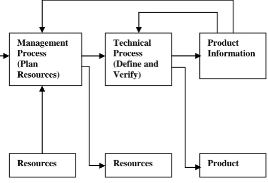
Fig 2: Relationship between Management Process and
Technical Process [6]
Executing the product introduction process involves linking two different, though not disjoints, processes along the various stages of the project’s life cycle. They are the technical processes (e.g. conception, design, prototyping, testing) and the managerial processes (e.g. identifying the required skills, identifying the required human resources, workflow management, etc.) as shown in Fig. 2. The managerial process monitors the resources, coordinates the activities of the parties involved, manages the communication and information flow, and supports the technical process via decision making and data management. The technical process creates and shapes the features of the project’s outcome (i.e. product) [7], [6]. In case of activities of the type test, depending on the result of the test, the control may go to one of the previous activities at the same hierarchical level or to an activity at the previous level in the same project or to an activity in a different project. Thus, the order of execution of the activities depends on the information that is generated from the activities. In order to find a representation for the activities and the dependencies among them, the relationships between activity and information need to be analysed in detail
Activities Controls
Process
People Systems
1 2
3 CE
1
3 2
Concurrent Engineering CE
People working in a new way
Automated processes
People sharing information
Management Process (Plan Resources)
Technical Process (Define and Verify)
Product Information
[image:2.595.308.572.264.444.2]X
Y
..
..
Activity 1
Activity 2
Output 1
Output 2
Output 3
Output 4
Input 2 Input 1 copy
copy
A3
A4
C2
A1
A2
C1
C2
A3
A4
C3
A1
A2
C1
[image:3.595.58.548.74.302.2]C4
Fig 3: Direct Dependency between Activities (based on class) [6]
X
Y
..
..
Activity 1
Activity 2
Output 1
Output 2
Output 3
Output 4
Input 2 Input 1 source to
derive
source to derive
A3
A4
C2
A5
A6
C5
C6
A8
A9
C3
C4
A1
A2
C1
A7
[image:3.595.60.561.382.613.2]5.
ATTRIBUTE DEPENDENCY
ANALYSIS TOOL
Attribute dependency exists between two attributes if a change in one affects the others i.e if an attribute is dependent on other one. Fig. 5 shows an algorithm to show the dependency between the attributes by drawing arrows between the corresponding attributes. In this algorithm, E represents the destination cell in a worksheet. Cell addressees are segregated and collected in an array S. If the array is empty then the algorithm will exit. For every cell address in the array S, arrow is drawn from destination cell to source cell and the procedure is called recursively till the arrows are drawn for all the formulas in the worksheet.
Procedure Draw_Arrow_for_Precedents (E)
// E denotes the end or destination cell
Step 1: Move to the cell with the address E
Step 2: Read the formula from the current cell i.e E
Step 3: Destination E
Step 4: Segregate the cell addresses from the formula
Step 5: Collect the cell addresses say Cell_CA1, Cell_CA2, Cell_CA3, …. Cell_CAn as a set S.
Step 6: if S is empty then exit
Step 7: i 1
Step 8: For every cell address CAi in S
Step 9: Source CAi
Step 10: Draw an arrow/line from Destination to source
Step 11: Call Draw_Arrow_for_Precedents(CAi)
Step 12: i i+1 // Consider next cell address in Formula E //
[image:4.595.305.563.71.199.2]Step 13: end
Fig 5: Algorithm for Drawing Arrows for Precedents
Fig. 6 shows an algorithm to clear all the arrows which are drawn between the dependencies attributes. The algorithm starts with counting the number of arrows and assigning to a variable ‘n’. All the arrows are selected and deleted inside the loop and the loop continues till all the arrows are deleted.
Procedure Clear_Shapes
Step 1: Count the number of shapes and assign to “n”
Step 2: For i = 1 to n do
Step 3: Select a shape and delete
Step 4: i = i + 1
Step 5: end
Fig 6: Algorithm to Clear Shapes i.e Arrows
6.
RESULTS AND DISCUSSIONS
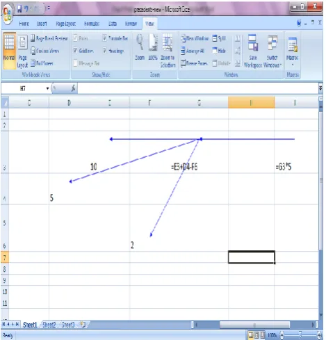
[image:4.595.47.285.225.603.2]Based on the algorithm shown in fig. 5, ‘DrawAllprecedents’ macro has been written. In fig. 7, arrows are drawn for precedents cells from the specified formula. For example, in the given excel sheet, three arrows are drawn for the formula G3=E3+D4-F6 since it contains three precedents cells E3, D4 and F6. Hence three arrows will be drawn from the cell G3 to the cells E3, D4 and F6. This shows the dependency among the cells. Likewise, the arrows are drawn for the formula I3=G3*5. This formula contains one precedent cell, G3. Hence one arrow will be drawn from the cell I3 to G3.
Fig 7: Draw Arrows to all Precedents Cells
[image:4.595.315.550.367.612.2]Parts and costs of a ball-point pen are shown in table 1. The total cost of the pen is 139.42. As it can be seen from the table 1, the cost of the barrel is higher compared to all other parts. A workbook has been created using the values / costs of the parts of the pen. Fig. 8 shows an excel sheet with the values specified in table 1 and the dependencies among the costs of the parts are represented using arrows.
Table 1. Parts and Costs of a Ball-Point Pen [10]
[image:5.595.323.549.105.554.2]Fig 8: Dependencies among the Parts of ‘Ball-point pen’
Table 2. Parts and Costs of Value Engineered Stapler [9]
Fig 9: Dependencies among the ‘Stapler’ parts and their Costs
Number Parts Cost (in Rupees)
1 Top 23.23
2 Base 29.03
3 Staple Support 26.54
4 Leaf Spring 21.57
5 Block 4.14
6 Spring Guide 16.59
7 Spring 6.63
8 Pin 2.48
Assembling 12.44
Total 142.70
Number Parts Cost (in Rupees)
1 Tip 32.92
2 Barrel 65.86
3 Cartridge 18.94
4 Top 12.35
5 Ink 8.23
6 Cap 0.82
[image:5.595.51.277.182.692.2] [image:5.595.319.541.387.685.2]Table 2 shows parts of the ‘stapler’ and their costs. The total cost of the ‘stapler’ is 142.70 including the cost to assemble the ‘stapler’. Fig. 9 shows the dependencies among the cost of parts of a ‘stapler’. At column A the costs of ‘base’, ‘top’ and ‘pin’ are specified as per the rate given in the table 2. These three parts are assembled to ‘Assembly-1’. The cost of ‘Leaf spring’ and ‘Staple support’ are given in column D and assembled to ‘Assembly-2’ in column F. The third assembly consists of the cost of ‘Block’, ‘Spring’ and ‘Spring guide’. The total cost of the stapler is represented in column N and it is calculated by adding ‘Assembly-1’, ‘Assembly-2’, ‘Assembly-3’ and assembling process cost.
7.
CONCLUSION AND FURTHER
WORK
Product Introduction process involves evolution of product design and product data. Concurrent engineering is practiced in industries to reduce product introduction time. Concurrent engineering involves team working and hence demands continuous exchange of information at various levels of completeness of information. In order to accelerate the communication of information among activities, it is necessary to identify the dependencies among input information and output information classes / attributes of activities. In case of derived attributes, it would be necessary to store the method for derivation; the derivation method may be a formula or rule. In this paper, the dependencies among the attributes are done by using formula. Further work can be done by specifying rules.
8.
REFERENCES
[1] Brooks B., 1995, Time Equals Money - But where does it all go?, IEE Colloquium on Concurrent Engineering - Getting it Right First time, (London, 8 June), pp. 4/1 - 4/23.
[2] Budill E.J., 1989, How Process Logistics Planning Can Enhance the Effectiveness of Simultaneous Engineering, Proceedings of the Simultaneous Conference, pp. 73-81.
[3] Carver G.P., Bloom H.M., 1991, Concurrent Engineering through Product Data Standards, (U.S.: Department of Commerce, May).
[4] Cleetus K.J., Uejio W.H. (Editors), 1989, Blackboard for Design Evolution, Red book of Functional Specifications for the DICE Architecture, Working draft, pp. 75-93.
[5] Crabtree R.A., Baid N.K., Fox M.S., 1993, An Analysis of Coordination Problems in Design Engineering,
Proceedings of the International Conference on Engineering Design (ICED ’93, The Hague, 17-19 August), pp. 285-292.
[6] Devi Thirupathi., 1998, “Integrated Information Model for Managing Product Introduction Process”, Ph.D. Thesis, University of Warwick, UK, September.
[7] Devi Thirupathi., Roy R., 1997, Towards an Information Model for Concurrent Engineering in Product Introduction, Proceedings of the First Post-Graduate Symposium on Knowledge Exchange - Manufacturing, Logistics and Management (KE-MLM’97, Loughborough University, 24 July), pp. 13-21.
[8] Hales C., 1987, Analysis of the Engineering Design Process in an Industrial Context, Ph.D. thesis, (Cambridge: University of Cambridge).
[9] John Fox, 1993, Quality through Design, McGraw-Hill Companies.
[10] Kenneth L., Brian F., 2006, Purchasing and Supply Chain Management, Prentice Hall Publications, Seventh edition.
[11] Lamghabbar B., Yacout S and Ouali M.S., 2004, Concurrent optimization of the design and manufacturing stages of product development, International Journal of Production Research, 42, 4495–4512.
[12] Lindberg L., 1993, Notes On Concurrent Engineering, Annals of the CIRP, 42(1), pp. 159-162.
[13] Londono F., Cleetus K.J., Nichols D.M., Iyer S., Karandikar H.M., Reddy S.M., Potnis S.M., Massey B., Reddy A., Ganti V., 1992, Coordinating a Virtual Team, CERC Technical Report Series, CERC, West Virginia University.
[14] Pahl G., Beitz W., 1984, Engineering Design, Edited by Wallace K., (London: Design Council).
[15] Pahl G., Beitz W., 1996, Engineering Design - A Systematic Approach, Edited by Wallace K., Blessing L.T.M., Bauert F., (London: Springer_Verlag).
[16] Rosenthal S.R., 1992, Effective Product Design and Development - How to Cut Lead time and Increase Customer Satisfaction, (Illinois: Business One Irwin).
[17] Stark J., 1992, Engineering Information Management Systems - Beyond CAD/CAM to Concurrent Engineering Support, (Van Nostrand).
![Fig 3: Direct Dependency between Activities (based on class) [6]](https://thumb-us.123doks.com/thumbv2/123dok_us/8105626.789327/3.595.60.561.382.613/fig-direct-dependency-activities-based-class.webp)
![Table 2. Parts and Costs of Value Engineered Stapler [9]](https://thumb-us.123doks.com/thumbv2/123dok_us/8105626.789327/5.595.319.541.387.685/table-parts-costs-value-engineered-stapler.webp)
