Modeling Aspects for Step and Bus Topologies
under Distributed Computing System
Taskeen Zaidi
Deptt. of Computer Science Babasaheb Bhimrao Ambedkar University
Vidya Vihar, Rae Bareli, Lucknow
Vipin Saxena
Professor, Deptt. of Computer Science Babasaheb Bhimrao Ambedkar University
Vidya Vihar, Rae Bareli Road, Lucknow
ABSTRACT
The distributed computing approach has the several advantages over the old centralized computing approach like reduction of execution time and low cost involvement. Many researchers have applied the modeling concepts for the distributed computing system. The most popular approach is the object-oriented modeling also known as Unified Modeling Language (UML) approach which is a platform independent to any programming language. In the present work, Unified Modeling Language (UML) is used for the various aspects used in the distributed computing system. This paper consists of the modeling of newly developed step topology and compared with the bus topology under distributed computing system. UML activity diagrams are designed for these topologies and the diameters of bus and step topology are also computed by varying the nodes through hope count and represented in the form of table and graph.
Keywords
Distributed computing system, UML, Activity diagram, Step topology, Diameter.
1.
INTRODUCTION
Topology plays an important role for static interconnection of the computer systems. In the literature, many topologies appeared but some of them like star, bus are frequently used by the network administrator for establishment of the computer centre. In this connection, an important reference Tanenbaum [1] has written a famous book on computer networks which describes the generation of computer networks including network topologies, adhoc networks, wireless networks etc. Since, many of the software industries are using the concept of the distributed computing systems for execution of the tasks on the local area network which are well described by Frouzan [2] and it consists of detailed processing of networks, structures, models, classification and categories of networks. The distributed computing algorithms for execution of the processes are available in Milenkovic [3] who has also explained security threats caused by users and providers on the network. In the current scenario and faster transfer of the data, dynamic connections are also used by the network administrators which are based on the various types of topologies like hyper cube, digital bus, etc. and these are available in Hwang [4]. If one is transferring the data from one machine to the another machine, then the architecture of the computer systems play an important role for transferring of the data and these are well described by Mano[5]. Patterson et al. [6] has described the architectures and recent technologies used in the computers. Sharing of resources, data, files, audios, videos and various information in distributed environment as well as mutual exclusion of tasks for static connection are available in[7-8].
On the other hand, software and hardware architecture research problems can be solved through the modeling language. Due to evolution of the object-oriented technologies, a well known modeling language called as Unified Modeling Language [UML] is used by the various researchers and this modeling language has been created by the OMG group [9-10]. This language is also used for computing the various performance metrics to create the applications for parallel and distributed systems which have been proposed by [11-12]. Booch [13] has described the various stages of the development of the UML and currently version of the UML is used by the various researchers is 2.0. The use of UML for solving the research problem, how to draw read and create projects to make it effective are well explained in [14]. The various prospects of UML to create effective projects are illustrated by Gomaa [15]. Recently, Saxena and Zaidi [16] have proposed a step topology for static interconnection of computer system under distributed environment. In India, distributed computing approach is used to establish the National Knowledge Network (NKN) project with main objective to connect the higher learning Institutions for sharing the knowledge. Recently, Saxena and Zaidi [17] have studies a case study for computing the % utilization of NKN alongwith the advantages and difficulties faced under this project. Saxena et al. [18] have also measured the performance of processors for different object-oriented software systems under distributed environment. UML modeling of a protocol for establishing the mutual exclusion in the distributed computing system has been done by Saxena and Arora [19]. Ladder topology which is used for the circuit designing and later on performance of this topology is evaluated by the authors [20-21]. Performance of various static and network topologies have been computed by Saxena and Raj [22-23]. Saxena and Zaidi[24] has computed the performance of Endian operating system in which user’s identification has been monitored by internet protocol (version4) and users are connected under static step topology. On the basis of above, the present work emphasized on the modeling aspects for the step topology and it is compared with the similar kind of famous bus topology. The UML activity and class diagrams are designed for these two topologies used for the static interconnection under the distributed computing environment. Before this, a process id is created for the execution of the processes on the static interconnection and later on a comparison between bus and step topologies are also explained in the form of table and graph.
2.
BACKGROUND
2.1
A Distributed System
Processing_ Element_N N distributed computing system. Distributed computing reduces
[image:2.595.66.273.156.301.2]cost of infrastructure, allows resources sharing, files sharing, audio sharing, video sharing, data sharing, etc. In India interconnections of these systems is called as National Knowledge Network (NKN) and it is implemented under Next Generation Network (NGN) services. An interconnection of devices under distributed system is shown below in fig. 1.
Fig. 1: A distributed system
2.2 Process
A process is defined as subprograms, subtasks, macros, subroutines, sub processes which are executed by the processor. PEC i.e. Process Execution Controller is attached to the processes to execute the tasks. The PEC is controlled by the object under object-oriented technology. The class diagram of process is shown below in fig.2, stereotype processing unit is shown in fig.3 and instances and multiple instances of process are represented in figs.4(a) and(b).
Fig. 2: UML class diagram of process
Fig. 5: SEND and RECEIVE operations in process Communication
[image:2.595.324.538.252.342.2]With the help of SEND operation process P0 can send message /request to process P1 and the request is received with RECEIVE operation by process P1 as shown in fig. 5.
Fig. 6: UML class diagrams of SEND and RECEIVE message
The sending and receiving of messages through UML from processing unit are shown in the fig. 6.
2.3 Topologies
Various kinds of static and dynamic topologies have been proposed by researchers from time to time to connect computers under distributed computing environment. Various types of static topologies like star, tree, ring, mesh etc as well as dynamic topologies like fat tree, barrel shifter, systolic array came into existence. Authors have proposed a new static step topology [23] for interconnection of various computers under distributed computing environment. N number of computers can be connected by varying the cable length as represented in fig. 7(a).
2
.4 A PEC Representation of Static
Network Topologies
<<processing_unit>> Process +Process_id: integer +Process_size: integer +Process_in_time: string +Process_out_time: string +Process_priority: integer +Process_create() +Process_delete() +Process_update() +Process_join() +Process_suspend() +Process_synchronize()
<<Stereotype>> processing_unit Process_id: integer Process_type: string Process_cardianality: integer
Process
Base Class
Send <<processing
_element>>
Receive <<processing _element>>
Acknowledgement Send message Send
P0
Receive P1
[image:2.595.322.538.551.748.2]Fig. 7b: A PEC representation of bus topology
In step topology, PEC executes the process on its own node or on next neighbouring node through message passing techniques. N numbers of computer systems are connected in static step topology under distributed environment as represented in fig. 7(a). While on the other hand, in bus topology, processes are shared on a single communication line as represented in fig. 7(b).
3. MODELING ASPECTS OF TOPLOGOIES
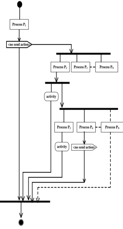
A well known Unified Modeling Language is used to represent step and bus topologies by the class and activity diagram. The activities may be the categories of fork and join the two or more than two activities as represented in figs. 8(a) and 8(b), respectively. The activity diagram shows the functioning of the topology and for bus topology, it is represented in fig. 9. In this figure, let N processes are to be executed under distributed computing system through bus topology. The activity of first process is to be executed under PEC and remaining processes P2,……PN have to wait for the
activities and in the second phase the activity of P2 is
performed and in the same manner all the processes are to perform their activities which is in the form of execution of process, sharing of files, etc.
Fig. 8a Process fork Fig. 8b Process join
<no send action>
Process P2 Process P3
activity
Process P3
activity
Process PN
Process P1
Process PN
Process P4
<no send action>
Fig. 9:UML activity diagram for bus topology
In the similar manner, the activity diagram for new kind of step topology is designed and represented in the fig. 10. It is designed in such a way that a first process P1 will perform its
activities then only P2 and P3 will wait and remaining
processes shall be in queue then in step topology if link between two nodes i.e. Processing_Element1 and Processing_Element2 fails then in such case Processing_Element1 can communicated with Processing_Element3 by using the alternate path which is not available in the bus topology. In this manner all the processes P2,P3……..PN shall be executed and represented in the
following figure.
Processing_ Element_1
Processing_ Element_2
Processing_ Element_N Processing_
[image:3.595.64.271.78.117.2]<no send action>
Process P2 Process P3
activity
Process P3
Process PN-1
activity
Process PN-2
Process PN
activity
[image:4.595.55.273.71.354.2]Process P1
Fig. 10b:UML activity diagram for bus topology
4. Comparison between Bus and Step
Topologies
[image:4.595.316.554.72.266.2]From the figs. 7(a) and 7(b), the diameters of bus and step topologies are computed and shown below in the following table it is observed that the diameter of step topology is same as the bus topology but step topology has the advantage that if link between two nodes fail then it will follow the alternate
Fig.11 Representation of diameter for step topology
5. CONCLUSIONS
From the above work, it is concluded that the UML is a powerful modeling language to represent the software and hardware architecture research problems. In the above work, the activities of a newly developed step topology are demonstrated and compared with the help of bus topology. The execution of the process is done in the processing unit which is fully responsible for execution of the processes and these are demonstrated with the help of UML class diagrams for the step and bus topologies. The comparison between step and bus topology is also demonstrated and observed that if the middle node failures between N1 and N3 i.e. N2 then in the
step topology the data is transferred from N1 to N3 as this link
does not exist in the bus topology although the diameter will be same in both the cases.
6. REFERENCES
[1] Tanenbaum A. S.,“Computer Networks”, Prentice Hall, 2010.
[2] Frouzen, B. A.,“Data Communications and Networks”, Tata McGraw Hill, 2006.
[3] Milenkovic, M., “Operating Systems:Concepts and Design”, Tata McGraw Hill, 1987.
[4] Hwang, K., “Advanced Computer Architecture: Parallelism, Scalability, Programmability”, Fourteen
0 2 4 6 8 10 12
1 2 3 4 5 6 7 8 9
Number of Nodes
Diameter (Step Topology)
Number of Nodes Diameter (Bus Topology)
Diameter (Step Topology)
2 1 1
3 2 2
4 3 3
5 4 4
6 5 5
7 6 6
8 7 7
9 8 8
[image:4.595.49.285.422.565.2][8] Silberschatz,A. and Peterson, J.L., “Operating System Concepts”, Addison Wesley, 1988, Alternate Edition, 1988.
[9] OMG, “Unified Modeling Language Specification”. Available online via http://www.omg.org, 2001.
[10] OMG, “Unified Modeling Language (UML)–Version 1.5”, OMG document formal/2003-3-01, Needham MA, 2003.
[11] Pllana, S. and Fahringer, T., “On Customizing the UML for Modeling Performance Oriented Applications”. In<<UML>>, Model Engineering Concepts and Tools, Springer-Verlag., Dresden, Germany, 2002.
[12] Pllana, S.and Fahringer, T., “UML Based Modeling of Performance Oriented Parallel and Distributed Applications”, Winter Simulation Conference, 2002. [13] Booch, G., Rambaugh, J., and Jacobson, I., “The Unified
Modeling Language User Guide”, Twelfth Indian Reprint Pearson Education, 2004.
[14] Roff, T., “UML:A Beginner’s Guide”, Tata McGraw– Hill Edition. Fifth Reprint, 2006.
[15] Gomaa, H., “Designing Concurrent, Distributed and Real Time Applications with UML”, Proceedings of the 23rd International Conference on Software Engineering (ICSE’01), IEEE Computer Society, 2001.
[16] Saxena, V. and Zaidi, T., “Step Topology for Static Interconnection of Computer Systems under Distributed Environment”,3rd
World Conference on Information Technology organized by University of Bercelona, Nov. 14-17, 2012.
[17] Saxena, V. and Zaidi , T., “National knowledge Network versus Information Communication Technology”, In Proceeding of University Department of Mathematics, B.R.A. Bihar University,Muzzafarfur,India,11-12 Feb.,2012.
[18] Saxena, V., Arora, D. and Ahmad, S.,“ObjectOriented Distributed Architecture System through UML”, Conference IEEE, International Conference on Advances in Computer Vision and Information Technology, ACVIT-07, ISBN 978-81-89866-74-7, pp.305-310, 2007. [19] Saxena, V. and Arora, D., 2008 “UML Modeling of a Protocol for Establishing Mutual Exclusion in Distributed Computer System”, International Journal of Computer Science and Network Security, Vol.8, No.6, pp.227-235, 2009.
[20] Shiramizu, N., Masuda, T., Nakamura, T. and Washio, K., “Scalable Transformer Model Based on Ladder Topological Equivalent Circuit for SiRFICs”, doi: 10.1109/SMIC. 2010.5422954,Letter Symbols for Quantities, ANSI Standard Y10.5-1968, 2010.
[21] Koohazadek, M. and Tamijani, A., “Miniaturized Transmission Lines Based on Hybrid Lattice-Ladder Topology, IEEE Transactions on Microwave Theory and Techniques, Vol.58 (4), 949-955, 2010.
[22] Saxena, V. and Raj, D., “Local Area Performance using UML”, International Journal of Advanced Networking & Applications,Vol.2, page 614-620, 2010.
[23] Saxena, V. and Raj, D., “Modeling of Staic Network Topologies through UML”, International journal of Intelligent Information Processing 2(2) July-December, pp.189-197, 2008.