Design and Implementation of Radio Link Control
as a Part of the WCDMA Radio Interface
Protocols by using SDL
Amin S. Ibrahim
Engineer
,
System designer Electronics and Communications EngineeringDepartment, Thebes higher institute of Engineering, Cairo,
Egypt
Abdelhalim Zekry
PH.D., Professor Electronics and Communications Engineering
Department, Faculty of Engineering,ain shams University, Cairo, Egypt
Hussein A. Elsayed
PH.D., asist. Professor Electronics and Communications Engineering
Department, Faculty of Engineering,ain shams University, Cairo, Egypt
ABSTRACT
The Universal Mobile Telecommunication System (UMTS) is the most powerful technology in the third generation (3G) mobile communication and it is the base for the 4G technology. The Wide band Code Division Multiple Accessing (WCDMA) is the radio access technique for the UMTS system. The Radio Link Control (RLC) Protocol is apart from layer 2 of WCDMA protocol architecture. In this paper, we present the RLC Protocol and focus on the Acknowledged Mode (AM) of RLC to explain its complicated functionality. The used methodology is the design, implementation, and verification of the functions of the AM RLC mode using SDL language. The AM RLC functions are confirmed and verified via the simulation results.
Keywords
: UMTS, RLC, AM, SDL1.
INTRODUCTION
The Access Stratum protocol (AS) as a part of the UMTS radio interface in the WCDMA system consists of Radio Resources Control (RRC) [1], Radio Link Control (RLC), and Medium Access Control (MAC).
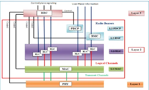
Figure 1 shows the physical layer (L1), the Data Link Layer (L2), and the Network Layer (L3). The layer 2 splits into two layers: the RLC and the MAC. In addition, two other sub-layers: the Packet Data Convergence Protocol (PDCP) and the Broadcast/Multicast Control Protocol (BMC) in the user plane [2].
RLC protocols provide a range of transport services between RLC entities in both UE and RNC sides. The RLC sub-layer provides three types of data transfer services of operation;
Transparent Mode (TM), unacknowledged mode (UM), and Acknowledged mode (AM) Mode.
Recently, the researchers have provided call handling logic, message transfer procedures and configuration parameter values in the RRC. In addition, they have represented the RLC Coordinator process as part of RLC sub layer in Access Stratum system [3]. A light version of the LTE protocol for the access stratum user plane uplink and downlink connection has modeled by using the SDL Suite tool. The packet propagation from L2 to L3 has focused only on the UM mode in RLC process by using the packet switching techniques. In addition, the ARQ procedure has not implemented in this version and a unidirectional channel has been assumed [4].
The Specification and Description Language (SDL) describes, designs, and verifies the RLC sub-layer especially the AM mode. ITU Recommendation Z.100 standardizes SDL [5]. SDL is one of many introduced suits by Telelogic tau that is a leading toolset for analyzing, designing, testing and implementing reliable real-time and other advanced software systems. The SDL Suite consists of a graphical editor and syntax analyzer, a simulator and validator, and several optimized code generators for compilation to executable code [6].
The design and verification include the following functions: Error Correction (ACK/NACK), Flow Control, Sequence number check, segmentation, concatenation, reassembly, Add Header, and Data Transfer.
International Journal of Computer Applications (0975 – 8887) Volume 56– No.16, October 2012
Fig 1: Radio interface protocol structure
2.
ACKNOWLEDGE MODE MODEL
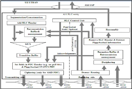
Figure 2 shows the internal units of AM-RLC model and the connections between them. In AM model, both the transmitting and the receiving side are combined into one entity for both UE and RNC, There are two types of the data in AM RLC: user data called Protocol Data Unit (PDU) and control data (STATUS PDU).
The transmitting side of the AM-RLC entity receives the Service Data Unit (SDU) at the UE higher layer through the Service Access Point (AM-SAP). RLC SDUs are segmented into multiple RLC PDUs. In the concatenation, RLC PDU may contain segmented or concatenated RLC SDUs. The header is a control field in the front of PDU. It contains two-fixed octets, which contain D/C field, the Sequence Number (SN) of PDU, Poll bit (P), and the Header Extension (HE) to extend the header. In addition one /or many optional octets, which contain the Length Indicator (LI) field for the concatenation function, Extension (E) field to indicate the following octets(data or optional header), and a special LI for Padding function (only in last PDU). After this function, a MUX is used to place a copy of the PDUs in the retransmission buffer and to forward it to the transmission buffer. Before data transmission, the p bit is added in the header setting to request the control data from Rx. Finally, each PDU is Ciphered and transferred into Rx- RNC side [7].
In the receiving side of the AM-RLC entity, the reception buffer receives and buffers the PDUs from Tx. One of the following two possibilities occurs when Tx triggers a P bit:
i) Positive Acknowledgement (ACK): the reception buffer receives All PDUs correctly from Tx and a p bit is detected. The Rx acknowledges its peer Tx
side by The Acknowledgement super-field (ACK SUFI), which is one of different types of super-fields. It is included in the STATUS PDU that is transmitted into a retransmission buffer. ACK SUFI carries the Last Sequence Number (LSN) of the PDUs to inform Tx that all PDUs before LSN are received correctly. This causes the retransmission buffer to delete all PDUs that were previously stored, except the PDU of LSN, which should be transmitted. A transmitting window size (buffer) is updated by the number of PDUs that were previously transmitted, while a Receiving window size is updated by each received subsequent PDU to avoid the over flow called Flow control. The reassembly unit reassembles all received PDUs to form the SDU that is sent to the upper layer [8].
Fig 2: Acknowledged mode model
3.
MODEL DESIGN
AND
IMPLEMENTATION
An SDL static structure forms a system. A system consists of blocks. A block is composed of processes. The SDL system structure describes the model design graphically in three hierarchical levels: AS System design, RLC block design, and AM process design.
3.1
AS system design
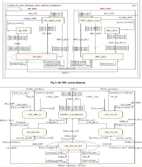
The access_stratum_radio_interface_protocols system is shown in figure 3. This system consists of Upper Layer, RRC, and RLC block from top to down in both UE and RNC Sides as described in Fig 1. In User Equipment (UE) side, these blocks are termed UE_Upper_Layer, UE_RRC, and
UE_RLC respectively. In Radio Network Control (RNC) side, it is called RNC_Upper_Layer, RNC_RRC, and
RNC_RLC respectively. In the user plane, the Upper Layer block is the source of information to RLC block. While in the control plane, the RRC block configures the RLC block by signaling messages and carries all the configuration parameters of the layer 3 and the layer 1. A channel is a connection among the Blocks in this system like a
Radio_interface that is a connection between UE_RLC and RNC_RLC blocks in both sides.
3.2
RLC block design
Figure 4 represents the UE_RLC block. We see that this block consists of five main building processes representing the three modes of operation. These processes are the UE transparent Mode TM Transmitter and Receiver UE_TM_Tx,
and UE_TM_Rx, respectively, the UE unacknowledged mode UM receiver and transmitter UE_UM_Rx, and UE_UM_Tx, respectively and the front-end acknowledge mode AM transceiver UE_AM_Tx_Rx. This architecture is required to separate the processors for the transmitting and the receiving
side in TM and UM modes. In addition, the
UERLC_Coordinator manages the operation of the five processes forming the RLC via the received control parameters from the RRC block. The processes are connected via signal routes like Data_R, which is a route between UE_AM_Tx_Rx unit in UE_RLC block and RNC_AM_Tx_Rxunit in RNC_RLC block.
3.3
AM process design
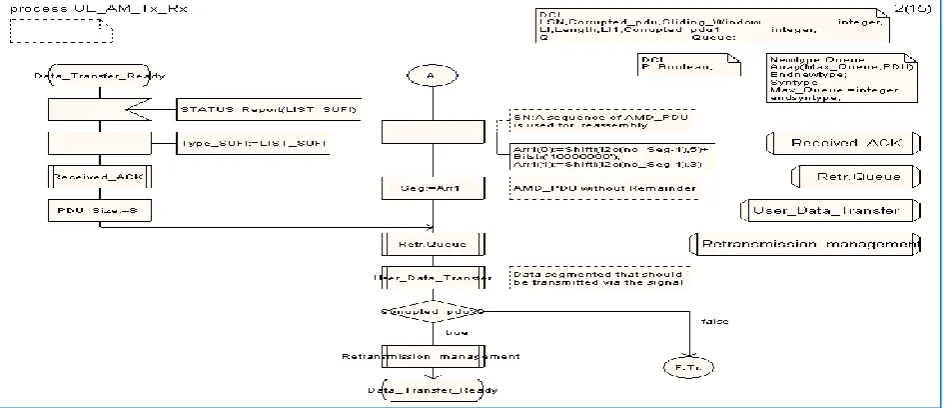
The AM process is a dynamic behavior of SDL components. AM process is a number of hierarchical transition procedures based on Extended Finite State Machine (EFSM).We developed the complete AM process using SDL Editor in Telelogic Tau. Figures 5 to 7 show representative parts of UE_AM_Tx_Rx and RNC_AM_Tx_Rx process. These flowcharts describe graphically the functions of the internal units in AM model as given in Fig 2.
Figure 5 explains the segmentation and NACK function in UE_AM_Tx_Rx process Tx entity. We see from this figure that, once the SDU is segmented into PDUs, the header is added in front of each PDU. A copy of it is saved in retransmission queue Retr.Queue procedure call. The PDUs are transmitted into the RNC side via User_Data_Transfer
procedure call. In case of NACK, a STATUS PDU is received through the input STATUS_Report (LIST_SUFI) from RNC side. This input carries LIST_SUFI ended by ACK_SUFI [8].
Received_ACK procedure call extracts SN of the lost PDU from LIST_SUFI. The SN of the received PDU before the lost one is extracted from ACK_SUFI. Before retransmission of the lost PDU into RNC side, Retransmission _management
procedure call deletes the received PDUs before the lost one.
International Journal of Computer Applications (0975 – 8887) Volume 56– No.16, October 2012
carrying each produced PDU from a segmented SDU. About ACK, the input STATUS_PDU (ACK_SUFI) carries ACK_SUFI that was received from RNC side to acknowledge successful reception [8]. Fig 7 illustrates the STATUS PDU creation in RNC_AM_Tx_Rx process for RNC side. In this figure, STATUS PDU divides into ACK_SUFI and
LIST_SUFI procedure calls. The first function at the front of
the figure detects if any of the two decisions ACK or NACK is sent to the UE side.
Finally, for SDL model implementation, we used Tele logic Tau 4.4 compiler to convert the SDL system design into C
[image:4.595.64.552.166.742.2]code via Microsoft Visual Studio C++ 6.0, which runs on the Windows XP operating system. The C source code generated amounts to 1.62 MB.
Fig 3: the SDL system diagram
Fig 5: a part of the process UE_AM_Tx_Rx- the segmentation function, NACK
[image:5.595.92.500.549.747.2]Fig 6: a part of the process UE_AM_Tx_Rx- a concatenated PDU, ACK
International Journal of Computer Applications (0975 – 8887) Volume 56– No.16, October 2012
4.
SIMULATION RESULTS
Telelogic Tau of SDL suite introduces a Simulator UI to analyze and verify the developed system model of the RLC-AM process. Since SDL is a high-level description language particularly suited for communication protocols, the simulation results are focused to demonstrate the functionality of the RLC protocol layer according to 3GPP standard [7]. Specifically, there are two complemented forms of the results in the Simulator UI: the executed transition trace, and Message Sequence Chart (MSC) simulator trace.
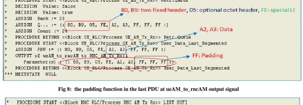
Figures 8 to 10 show some representative parts of the executed transitions trace of the AM RLC functions. These results are derived from the data and control PDU format in `the AM-RLC model. Figure 8 shows the PDU format (header+ user data) in octets with the padding function in AM mode by using FF octets to fill in the unused space in the last PDU. Figure 9 represents the NACK transition in AM mode. In this figure, the STATUS_Report output signal carries LIST_SUFI followed by ACK_SUFI parameters to request retransmission of the missing PDUs. Both SUFIs contain the required parameters for their functions. Finally, figure 10 introduces the ACK transitions in AM mode. In this figure, STATUS_PDU output signal carries ACK_SUFI parameters to acknowledge the successful reception. This SUFI carries the specified parameters for its function. The explained parameters of ACK and LIST SUFIs in fig. 9 and 10 were executed according to the control PDU (STATUS PDU) of AM mode in the protocol standard.
The message sequence chart MSC is the timing diagram of the transmission signals flow with the encoded PDU and STATUS PDU parameters among the layers in the level of processes for both UE and RNC sides. Figures 11 to 13 show
representative results of MSC simulator trace of the standard function procedures of the internal units in the AM diagram respectively as shown in figure 2. These signals flow of the figures represent also the connection lines among the internal units from up to down in AM diagram. The UE_AM_Tx_Rx process shows the internal units in UE-Tx entity. While, the internal units in the RNC-Rx entity is represented by RNC_AM_Tx_Rx process in the MSC results.
Figure 11 shows the configuration messages of the UE_AM_Tx_Rx process. These messages are transferred from the null (initialization the parameters) to
Data_Transfer_Ready states (transferring data) via
UE_RRC process.
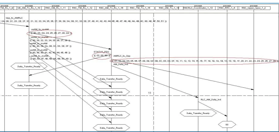
In Figure 12, the MSC shows and verifies the signals of the segmentation/concatenation, ACK, and Reassembly functions. The UPP_to_AMRLC signal carrying the SDU is received from UE_Upper_Layer process to UE_AM_Tx_Rx process. The SDU is segmented/or concatenated into PDUs.
The ueAM_to_rncAM signal carrying the PDUs is
transferred into RNC_AM_Tx_Rx process. STATUS PDU
signal is transferred from RNC_AM_Tx_Rx process to UE_AM_Tx_Rx process to return an acknowledgement to the sender. The PDUs are reassembled into the original SDU. The
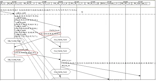
AMRLC_to_UPP signal with SDU is transferred into RNC_Upper_Layer process. Figure 13 represents the signal flow of NACK and retransmission function. Status Report
signal is transferred from RNC_AM_Tx_Rx process to the UE_AM_Tx_Rx process in order to inform the sender that the missing PDU requires the re-transmission. The
[image:6.595.51.554.428.602.2]Retransmission_Data signal retransmits the missing PDU into RNC_AM_Tx_Rx.
Fig 8: the padding function in the last PDU at ueAM_to_rncAM output signal
Fig 10: ACK_SUFI parameter of the STATUS_PDU output signal
Fig 11: a part of the MSC system - the signaling messages of UE_AM_Tx_Rx process
[image:7.595.57.518.524.743.2]International Journal of Computer Applications (0975 – 8887) Volume 56– No.16, October 2012
Fig 13: a part of the MSC system - NACK, retransmission
Finally, we see that the SDU is transferred from the UE side to the RNC side (peer-to-peer connection) successfully passing through the RLC functions in AM transfer mode. Therefore, we can conclude that the MSC develops a real time services and verifies the AM RLC mode in AS system.
5.
CONCLUSIONS
In this paper, we implemented successfully the functions of the AM RLC process which are a part of the protocol architecture of the WCDMA radio interface protocols. To carry out that, we studied the RLC protocol according to 3GPP standards. We utilized SDL to build a model of the RLC AM process. The process is then simulated using the soft ware suite Telelogic Tau. The simulation results showed and verified the correct functionality of the developed model, which complies with the 3GPP technical specifications.
Other processes in the RLC layer or any other control layer protocols can be implemented in the same way. Protocols of the LTE system can also be implemented and integrated by utilizing the great features of the SDL language. Least but not last, one can develop a hardware prototype model based on SoC system.
6.
REFRENCES
[1] Ahmed M. Abbas, Abdelhalim Zekry, Imbaby I. Mahmoud, and Hussein A. Elsayed.2012."An SDL Design and Implementation of a Radiation Monitoring
Network Using WCDMA", Journal of Communication and Computer 9, 602-612
[2] J. Pe´rez-Romero, O. Sallent, R. Agustı´ and M. A. Dı´az-Guerra. 2005. Radio Resource Management Strategies in UMTS
[3] P.J. Song, M.H. Noh, D.H. Kim. 2002. “Design and implementation of W-CDMA radio interface protocols using SDL development environments”, in: Proc. of International Conference of Lecture Notes in Computer Science, 442-452.
[4] A.Showk, D.Szczesny, S.Traboulsi, I.Badr, E.Gonzalez, A.Bilgic. 2009. “Modeling LTE Protocol for Mobile Terminals using a Formal Description Technique”, SDL'09 Proceedings of the 14th international SDL conference on Design for motes and mobiles,222-238
[5] ITU-T Z100, CCITT Specification and Description Language (SDL), 1996
[6] Telelogic, Tau 4.4 SDL suite platform program user, manual, 2010.
[7] Universal Mobile Telecommunications System (UMTS); Radio Link Control (RLC) protocol specification, (3GPP TS 25.322 version 7.7.0 Release 7), 2008